Accurate knowledge of the polarity of an electrical appliance is extremely important. After all, if you connect electrical equipment with incorrect polarity, it may either not work or be completely damaged. In most cases, the “plus” and “minus” of wires and contacts in such devices are indicated by letters, symbols or colors (on the case near the contacts there is a “+” and “-” marker, and the wires are black for minus and red for plus) .
But sometimes it happens that it is not possible to visually determine the poles. To do this, you can use either an ordinary polarity tester or improvised means.
Determining polarity with a multimeter
Sometimes it happens that a new electrical device that needs to be connected does not have polarity markings, or it is necessary to re-solder the wiring of a damaged device, and all the wires are the same color. In such a situation, it is important to correctly identify the poles of the wires or contacts.
But if you have the necessary instruments, a logical question arises: how to determine the plus and minus of an electrical appliance with a multimeter?
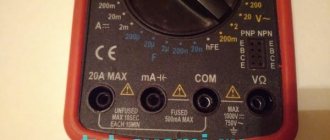
To determine the polarity, the multimeter must be turned on in the mode for measuring direct voltage up to 20 V. The wire of the black probe is connected to the socket marked COM (it corresponds to the negative pole), and the red one is connected to the socket with the VΩmA marker (it is, accordingly, a plus).
After this, the probes are connected to the wires or contacts and the device, the polarity of which needs to be determined, turns on.
If the multimeter display shows a value without additional signs, then the poles are determined correctly, the contact to which the red probe is connected is positive, and the contact to which the black probe is connected will correspond to the minus.
If the multimeter shows a voltage value with a minus sign, this will mean that the probes are connected to the device incorrectly and the red probe will be a minus, and the black probe will be a plus.
If the multimeter used to measure is analog (with an arrow and a display with gradations of values), if the poles are connected correctly, the arrow will show the actual voltage value, but if the poles are reversed, then the arrow will deviate in the opposite direction relative to zero, that is, it shows a negative current value.
The Importance of Polarity
It is very important for electrical appliances, because if they are connected incorrectly, they either simply will not start working or will fail.
Positive polarity is indicated by a plus sign (+), negative polarity by a minus sign (-). Most often, this information can be obtained by paying attention to the special markings. But sometimes it simply isn’t there, then you’ll have to determine the polarity yourself.
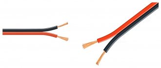
Manufacturers of video and audio devices use colors to indicate wires with different charges:
- red – plus;
- black – minus.
But there may be other options.
As for electrical networks, the cores when cutting the cable can have different colors:
- the phase wire is usually red or brown:
- zero is marked in blue or black.
But in practice, this color scheme is not always followed, so visual determination of plus and minus does not always work. Therefore, you need to be able to determine the polarity yourself, be it an ordinary electrical wire or any electrical appliance.
For this purpose, you can use a voltmeter or multimeter. A voltmeter is not always available in the house, but a multimeter is currently a fairly popular and at the same time affordable universal tester.
Determination of polarity by alternative methods
If it happens that you don’t have a multimeter at hand, but you need to find the polarity, you can use alternative and “folk” means.
For example, speaker wiring charges are checked using a 3-volt battery. To do this, you need to briefly touch the wires connected to the battery to the speaker terminals.
If the cone in the speaker begins to move outward, this will mean that the positive terminal of the speaker is connected to the positive terminal of the battery, and the negative terminal to the negative terminal. If the diffuser moves inward, the polarity is reversed: the positive terminal is connected to the minus, and the negative terminal to the plus.
If you need to connect a DC power supply or battery, but there are no polarity markings on them, and you don’t have a multimeter at hand, plus and minus can be determined by “folk” methods using improvised materials.
The easiest way to determine polarity that you can use at home is to use potatoes. To do this, you need to take one raw potato tuber and cut it in half. After this, two wires (preferably of different colors or with any other distinctive sign) with their bare ends are stuck into a cut of potato at a distance of 1-2 centimeters from each other.
The other ends of the wires are connected to the constant current source being tested, and the device is turned on (if it is a battery, then after connecting the wires, nothing else needs to be done) for 15-20 minutes. After this time, a light green spot will form on the potato cut around one of the wires, which will be a sign of a positive charge on the wire.
The second method also does not require any special devices or tools. To determine the polarity of the wires of a DC source, you will need a container of warm water into which two wires connected to the power source are lowered.
After connecting the device to the network, gas bubbles (hydrogen) will begin to appear around one of the wires - this is the process of electrolysis of water. These bubbles form around a source of negative charge.
The following method is suitable if you have an unused, working computer cooler. The method for determining polarity using this method is that the cooler must be powered from the uninterruptible power supply being tested. But often there are three wires in coolers:
- black, responsible for negative charge;
- red, responsible for positive charge;
- yellow is the speed sensor.
In this case, the yellow wire is ignored and is not connected anywhere. If, after connecting the cooler to a constant voltage source, the cooler starts to work, then the polarity is determined correctly, the plus is connected to the red wire, and the minus is connected to the black. And if the cooler does not work, this will mean that the polarity is incorrect.
Also, if a multimeter is not available, the positive and negative contacts of the battery can be determined using an indicator screwdriver.
To do this, you need to touch the indicator to one of the battery terminals, press your finger to the back of the indicator (to the contact on the handle), and touch the second terminal of the battery with your hand.
If the indicator starts to light, then the charge of the tested terminal with which it is in contact has a positive value, and if the indicator does not light up, the terminal is negative. But this method of determining polarity has one drawback.
If the battery is discharged or damaged (broken), the indicator will light up when in contact with both terminals, making it impossible to determine the battery poles.
How to determine the polarity of an unknown power source? Let's assume that you come across some kind of constant voltage power supply, battery or accumulator. But... it doesn’t indicate where the plus is and where the minus is. Yes, the matter can be quickly resolved with a multimeter, but what if you don’t have one at hand? Calmly. There are three proven working methods.
Using water
I think this is the easiest way to determine polarity. First of all, pour some water into a container. Preferably not metal. We remove two wires from a power source with unknown terminals, drop them into our water and look carefully at the contacts. Hydrogen bubbles will begin to form at the negative terminal. Electrolysis of water begins.
Using raw potatoes
Take a raw potato and cut it in half.
We plug our two wires from an unknown DC source into it and wait 5-10 minutes.
A light green color appears on the potato near the positive terminal.
Using a PC fan
We take a fan from the computer. It has two terminals, and sometimes even three. The third may be the yellow wire - the speed sensor. But we still won’t use it. We only care about two wires - red and black. If there is a plus on the red wire and a minus on the black wire, then the fan will rotate
If you didn’t guess right, then the blades will stand still.
We use a fan if it is known that the power source voltage is from 3 to 20 Volts. Applying a voltage of more than 20 volts to the fan is fraught with death.
Conclusion
In conclusion, I would like to say that these chips cannot be rolled with alternating current. And as you know, single-phase alternating current consists of two wires - phase and zero. For those who don’t remember how they can be determined, please look here. I would also like to wish you never to confuse the polarity, because “foolproof protection” (reverse polarity protection) is not installed in all electronic devices.
Designation and features of setting wire polarity
Wire polarity color codes
The color of the source wire insulation can also help determine polarity. In direct current networks, it is generally accepted that a wire with a red (hot) color sheath (insulation) is connected to the positive terminal of a constant voltage source, and black is assigned to the negative terminal. Taking into account the designation of a positive conclusion through a cross, this rule is remembered by the phrase “Red Cross”.
Features of wire polarity in DC circuits
The electrical circuit can use wires with insulation of other colors, which is necessary for the correct connection of various consumers. In this situation, you will need to individually check each of these wires with a multimeter. The base wire is always black. The voltage on the remaining wires must be positive.
Some types of electronic circuits, for example those assembled using operational amplifiers, can be powered from a bipolar source, i.e. They can be supplied with either positive or negative voltage. The main distinguishing feature of the source feeding them is the presence of three outputs, and the voltage on the two “hot” wires relative to the ground (black wire) is equal in magnitude and differs only in sign.
| Do you need quality wires and components? Let's collect your order! Submit your application online or call our toll free number 8 |
How to determine where the plus and minus are in a socket?
Speaker phasing improves sound reproduction quality. The lack of phase in wide-range speaker systems leads to a sharp drop in output at low and mid frequencies that is clearly noticeable to the ear.
At the same time, the output of high frequencies also decreases somewhat, and the frequency response of the system in this area has pronounced peaks and dips, that is, greater unevenness. Voices and instruments acquire a harsh, unpleasant timbre. In two-way acoustic systems, in the absence of phasing of low-frequency and high-frequency loudspeakers with each other, the same picture is observed.
When the low-frequency speaker is out of phase with respect to the high-frequency one, a dip in the frequency response appears in the band of joint operation of both loudspeakers. The width of this gap will be determined by the properties of the separation filter.
The presence of a dip can lead to a distinctly audible separate sound from the low-frequency and high-frequency loudspeakers. To identify the reasons that cause deterioration in the quality of loudspeakers when their phasing is incorrect, it is necessary to understand the operation of the emitter.
It has been established that when the moving system of the loudspeaker head oscillates, a periodic change in air pressure occurs, located in front of it; the front side will be called the surface of the diffuser facing the listener.
So, when the system moves forward, the pressure increases, and when it moves backward, it decreases. The change in pressure that occurs causes vibration of air particles, that is, the propagation of a sound wave. It is quite obvious that if two moving systems oscillate, then they must oscillate in phase; the forward and backward movement of both systems must occur simultaneously, for example, when S is working, then “the curtains are already moving.”
Otherwise, one of them will create an increase in pressure, and the other will create a decrease. Thus, mutual full or partial compensation of excess pressure will occur. Simultaneity, or in-phase, oscillations of moving systems is ensured if the direction of the current in the voice coil and the polarity of the magnet are the same for both heads. Since factories wind coils and magnetize permanent magnets in a certain way, the whole question comes down to the correct connection of the ends of the windings of the voice coils.
When connecting the heads in series, the end of one and the beginning of the other winding must be connected; When connected in parallel, the beginning and end of the windings are connected together. To make it easier to determine the beginning and end of the windings, the manufacturer uses a special coloring of the lead ends.
Phasing of loudspeaker heads can be done both by ear and by observing the displacement of the moving system. The above applies to speakers that do not contain additional filter elements or a matching transformer.
In the latter case, the phasing process becomes more complicated, since this requires a certain set of special measuring equipment. Let's look at examples of speaker phasing.
Phasing of single-way acoustic systems. To do this, a low frequency voltage of 50 or Hz is applied to the column. Low-frequency background can be obtained by touching the input circuits of the amplifier.
Finally, an audio frequency generator can be used as a low frequency voltage source. Listening to the level of low-frequency vibrations reproduced by the speaker, change the connection of the audio ends of one of the speakers to the opposite.
If the volume of the reproduced tone drops, then the first activation of the speakers was correct and should be left. If the level increases, the second switching on will be correct. To be more confident in the result obtained, three or four such switches should be made, one after the other.
The final position of the audio ends must be marked, preferably directly at the output terminals of the speaker system. Phasing of two-way acoustic systems. In this case, it is necessary to check the phasing of the low-frequency and high-frequency speakers with each other, if there are several of them in a link, then check the phasing of the links in relation to each other and, finally, the phasing of the low-frequency links in relation to the high-frequency ones.
The industry pays special attention to monitoring the correct and uniform arrangement of winding ends, color marking of lead ends and magnet polarity. Therefore, new speakers, as a rule, do not require checking the phasing of the heads, which should be done only if listening to them raises doubts about the correct phasing.
In all cases where it is necessary to check the phase alignment of the speakers of two-way speakers, only one reliable method can be recommended - visual. For speakers, the direction of displacement of the moving system is checked by applying a constant voltage of 1.5 - 4.5 volts to the voice coil, the source of which can be a AA or square battery: if the displacement is the same for all heads, then they are in phase.
In this case, the moving system must move forward, that is, the coil must come out of the gap. The movement of a moving system of full-range speakers or low-frequency speakers is clearly visible by the displacement of the diffuser. In extreme cases, in poor lighting, this movement is clearly visible with your fingers, which in a calm state should lightly touch the surface of the diffuser near the corrugation. For the same check of high-frequency dynamic heads, two methods can be recommended.
According to the first of them, a circle of paper, for example, newspaper, covering it, is placed on the hole in the lower flange, by which the head is attached to the horn. When you connect the constant voltage to the battery with a pulse, the circle will fly off or jump slightly if the plus was at the beginning of the winding. In the second method, the protective cover must be removed, and the movement of the diaphragm can be easily observed.
It must be remembered that correct phasing will be provided that the diaphragm moves towards the magnetic circuit and the coil is drawn into the gap, since the radiation of the head occurs through the core. Most two-way speakers contain crossover filters, matching transformers, or both. Connection of dynamic head speakers in two-way speaker systems. Connecting DC power to the speaker. Speaker 2GD Speaker 3GDE. Speaker 4GD-8E.
Tesla ARV Speaker 2GD Speaker: in half of the cases the beginning of the winding is not indicated. Online application Submit.
Other types of polarity
There are also more rare terminal locations, which can significantly complicate the identification procedure. For example, there are models that have a “6” polarity, which is visually determined by the presence of a positive terminal on the right, but the device body itself has an almost square appearance.
Polarity “9”, also known as “5”, is also not very common. You can find out that the battery belongs to this category by the location of the terminals exactly in the middle of the battery.
There is also polarity “2”, it is also found on trucks and special equipment. In this case, the terminals are located diagonally.
Polarity 2 and 9
Charger wire polarity by color
Let us assume that you have come across some kind of constant voltage power supply or battery. It does not indicate where the plus is and where the minus is. Yes, the matter can be quickly resolved with a multimeter, but if you don’t have one at hand, and we urgently need to start the car or power some trinket? An incorrect connection can damage the power source itself, or the device or unit being powered. This is where it is important to determine the polarity of the power source using improvised means. In this article I will tell you about three simple ways. Method number 1.
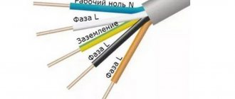
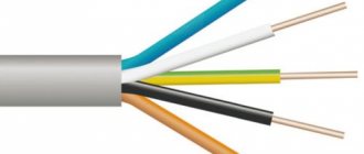
Marking of wires for alternating three-phase current
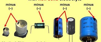
How to determine the polarity of a capacitor
The special color designation of the shell helps to determine the purpose of individual lines even without studying the accompanying design documentation:
- gray, purple, orange or red wire – phase;
- yellow and green stripes – grounding;
- blue or a combination of white and blue stripes is neutral.
Standard color marking of shells in three- and two-phase networks
Such designations simplify installation operations when laying power lines during the assembly of electrical panels. It is especially important to eliminate errors when hidden installation of communications inside building structures is used. In this case, correcting incorrect actions will be accompanied by increased costs.
Where are the plus and minus located on the radio?
If the polarity of the wires of the current source is unknown, then it can be determined with a magnetoelectric voltmeter, which has the polarity of the terminals marked. The polarity of the source is judged by the direction of deflection of the voltmeter needle. In the absence of a magnetoelectric voltmeter, the polarity of the source can be determined in the following ways. The copper rods of the wires connected to the current source are lowered into a glass of acidified water, for which 2-3 cm3 of electrolyte is added to the water. If the source voltage is more than 36 V, an electric lamp of the appropriate voltage is introduced into the electric current circuit. In this case, the rods in the glass should not touch one another. When the current source is turned on, a small amount of oxygen will be released on the positive rod in the form of small bubbles, and on the negative rod hydrogen will be released in the form of large bubbles and in large quantities. Determining the polarity of the wires of a direct current source using: a - acidified water; b - potato tuber; 1 - electric lamp; 2 - drive; 3 - negative rod; 4 - positive rod 2. Copper rods of wires connected to a direct current source are inserted at some distance from one another into a cut of a potato tuber and turn on the current source. Near the positive rod, the potato starch will turn greenish-blue.
Reverse battery polarity
Owners of foreign-made passenger cars should be aware that almost all cars use batteries with reverse polarity, indicated by the number “0”.
You can visually determine it as follows. If you position the battery so that the terminals and label are facing the person, then there will be a positive one on the right and a negative one on the left.
For trucks, the reverse polarity is called left and is indicated by the number “3”. The fact is that due to the large dimensions of the housing, the terminals are installed on the narrow side. In order to determine the polarity, you need to stand at the edge of the battery where the terminals are located. There will be a plus on the left and a minus on the right.
Reverse polarity
How to easily determine the polarity of the power supply wire
Forgot your password? Author subaru, Tell me how to do this? I connected it in different ways, I can’t tell by ear. Maybe there is some kind of mp3 file with a low-frequency recording, with which you can determine which way the speaker cone goes, just like with a battery?
Leave a comment 6. Connect the test leads to the terminals of the charger and turn it on. To check the polarity of the speakers, briefly touch the speaker terminals with wires from a 3-volt battery. When the speaker cone moves outward, the polarity of the speaker terminals matches the polarity of the battery.
Forgot your password? Forum General forums Music in the car Plus and Minus wires. Showing 1 to 16 of Topic Options Subscribe to this topic….
View full version: How to determine the polarity when connecting a thermocouple with a temperature compensation wire. Sometimes I get confused when connecting the thermocouple to the TRM. Within a range of up to 30 degrees, the TRM with one or another connection of the polarity to the thermocouple with a temperature compensation wire shows either 25 or 30 degrees. Which is the correct largest or smallest value? Sometimes there is no time to run for a thermometer. If it were in the minus, there would be no questions, but here the degrees jump, well, it seems that it happened even more.
Which outlet? There is a phase and a zero. You can determine it using an indicator screwdriver: where the phase is, it will light up, where 0 is not. If we are talking about a socket where the voltage is constant, for example a telephone socket, you can determine the polarity using a multimeter tester, or an LED with a resistor, the resistor must be designed for the appropriate voltage.
How to correctly determine the polarity on wires in a car
If the voltage on the car is checked, the course is set to search for a constant one. 20W is the correct setting if you are testing the battery. Therefore, you need to adjust the dial to the desired range/setting and connect the probes to whatever component you want to get a reading for.
You may be interested in this: How to calculate grounding
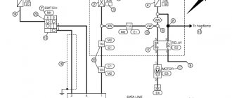
How to check a headlight with a multimeter
Multimeter
To check the headlight wiring, you need to find the ground wire. There are 2-4 wires coming from the connector that connects to the light bulb. Where there are two or three wires, only one of them is ground, while four-wire connectors will have two grounds.
To test the wires on the headlight, you need to set the multimeter to resistance. You can place one of the probes on the ground and the other on the negative pole of the car battery.
Note! If continuity is not read, then there is a problem with the ground wire, meaning it needs to be replaced.
How to Test a Car's Ground Wire Using a Multimeter
To test ground wires, start by measuring resistance. Test along the wiring to check the reading is 5 ohms or less. If it exceeds, you will need to check the wire further. You need to switch the multimeter to constant voltage and turn on any electrical part that is having problems. It's worth double-checking the wire to make sure the reading doesn't exceed 0.05V. If it does, you'll need to use a different ground location or use a tie strap.
How to Check if a Fuse Has Blown Using a Multimeter
Troubleshooting a fuse using a multimeter is extremely easy. You need to set the multimeter to the lowest ohm setting and place the probes on both sides of the fuse covers. Fuses do not have polarity, so the contacts used will not show values.
Circuit breakers
Note! If the resistance value is very low, then the fuse is working perfectly. If the resistance value does not change after connecting the contacts, the fuse has blown.
You can also test the fuse using a test light. You need to turn on the key and touch both sides of the fuse with the tip of the test light. If it lights up, the fuse is good. If it does not light up, the fuse needs to be replaced.
How to use a multimeter from a car battery
If you're having trouble starting your car, one of the most common reasons is a weak battery. This is something that can be easily checked using a multimeter, which will also give an accurate idea of how much charge the battery actually has left. Testing your car battery first is a great way to rule out a likely cult for many electrical problems.
When testing a car battery, you need to check the voltage by setting the multimeter to 20 V DC. It is necessary to connect contacts to both terminals of the battery that match the color. It is better to turn on the headlights to get accurate information regarding the charge.
Important! The headlights must be turned on when the engine is stalled.
In most cases the reading will be somewhere between 11.8 V and 12.6 V. The higher the voltage reading, the more charge there is in the battery. A reading of 12.5V means the battery is almost fully charged, while a reading of 11.9V means the battery should be replaced soon.
You may be interested in this Features of the cross section
Checking the charger
Electronic devices use adapters to convert alternating current supplied from wall outlets to direct current. Once converted to direct current, current flows in one direction, hence the term direct current.
What color is the positive wire on the charger?
Note! One wire is positive, which conducts current to the device, and the other is negative, which completes the circuit. The direction of flow is called polarity and is marked on chargers using a diagram. If there is no diagram on the charger, it is worth checking the polarity.
The color polarity of the charger wires does not matter.
To determine if the charger is fit for use, do the following:
- Connect the charger to a power outlet.
- Turn on the multimeter and set the settings to DC voltage. Most multimeters indicate this setting as VDC.
- Insert the red positive contact into the hole in the charger tip.
- Touch the black negative terminal and the outer metal part of the charger tip.
- Monitor the multimeter readings. You may see a positive or negative number indicating the DC output voltage of the charger. If the number is positive, then the polarity on the inside of the charger tip is positive. If the number is negative, then the polarity inside is negative.