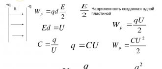
A capacitor is an element of an electrical circuit consisting of conducting electrodes (plates) separated by a dielectric. Designed to use its electrical capacity. A capacitor with a capacitance C, to which a voltage U is applied, accumulates a charge Q on one side and Q on the other. The capacitance here is in farads, the voltage is in volts, and the charge is in coulombs. When a current of 1 A flows through a capacitor with a capacity of 1 F, the voltage changes by 1 V in 1 s.
One farad has a huge capacitance, so microfarads (µF) or picofarads (pF) are usually used. 1F = 106 µF = 109 nF = 1012 pF. In practice, values ranging from a few picofarads to tens of thousands of microfarads are used. The charging current of a capacitor is different from the current through a resistor. It depends not on the magnitude of the voltage, but on the rate of change of the latter. For this reason, measuring capacitance requires special circuit solutions based on the characteristics of the capacitor.
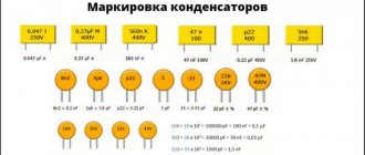
Designations on capacitors
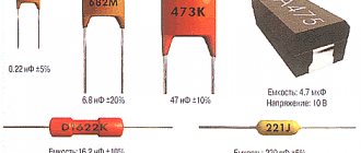
The easiest way to determine the capacitance value is by the markings on the capacitor body.
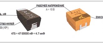
Electrolytic (oxide) polar capacitor with a capacity of 22000 µF, designed for a nominal voltage of 50 V DC. There is a designation WV - operating voltage. The marking of a non-polar capacitor must indicate the possibility of operation in high voltage alternating current circuits (220 VAC).
Film capacitor with a capacity of 330000 pF (0.33 µF). The value in this case is determined by the last digit of a three-digit number, indicating the number of zeros. The following letter indicates the permissible error, here - 5%. The third digit can be 8 or 9. Then the first two are multiplied by 0.01 or 0.1, respectively.
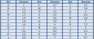
Capacitances up to 100 pF are marked, with rare exceptions, with the corresponding number. This is enough to obtain data about the product; the vast majority of capacitors are marked this way. The manufacturer can come up with his own unique designations, which are not always possible to decipher. This especially applies to the color code of domestic products. It is impossible to recognize the capacity by erased markings; in such a situation, you cannot do without measurements.
Check procedure
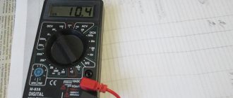
Touching contacts with probes
A multimeter can identify causes of malfunction such as breakdown, which entails the destruction of the dielectric separating the plates, and the current flows directly, while the capacitor itself, in fact, becomes a simple conductor. Or it does this partially, losing its capacity, becoming an additional active resistance in the electrical circuit.
The capacitor itself, due to its operating principle, passes only alternating current, and in no case direct current, therefore its resistance, measured between the terminals, is quite large and is limited by a very small leakage current through the dielectric that separates its working plates, which accumulate charge.
In non-polar capacitors, the role of dielectric of which is played by mica, ceramics, paper, glass, air, the leakage current is infinitely small, and the resistance is very large and when measured between the terminals with a digital multimeter, the device will show infinity in the form of 1 on the digital display. Therefore, in the event of a breakdown, its resistance, measured at the terminals, is quite small - up to several tens of ohms.
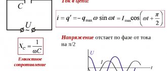
Calculations using electrical engineering formulas
The simplest RC circuit consists of a resistor and a capacitor connected in parallel.
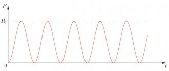
After performing mathematical transformations (not given here), the properties of the circuit are determined, from which it follows that if a charged capacitor is connected to a resistor, it will discharge as shown in the graph.
The product RC is called the time constant of the circuit. When R is in ohms and C is in farads, the product RC equals seconds. For a capacitance of 1 μF and a resistance of 1 kOhm, the time constant is 1 ms, if the capacitor was charged to a voltage of 1 V, when a resistor is connected, the current in the circuit will be 1 mA. When charging, the voltage across the capacitor will reach Vo in time t ≥ RC. In practice, the following rule applies: in a time of 5 RC, the capacitor will be charged or discharged by 99%. At other values, the voltage will change exponentially. At 2.2 RC it will be 90%, at 3 RC it will be 95%. This information is sufficient to calculate the capacity using simple devices.
Other techniques
Capacitance can also be determined using a ballistic galvanometer. The formula used for this is:
Where:
- Cq is the ballistic constant of the galvanometer;
- U2 - voltmeter readings;
- a2 is the deflection angle of the galvanometer.
Determining the value using the ammeter-voltmeter method is carried out as follows: the voltage and current in the circuit are measured, after which the capacitance value is determined by the formula:
The voltage with this determination method must be sinusoidal.
Measuring the value is also possible using a bridge circuit. In this case, the AC bridge circuit is given below:
Here one arm of the bridge is formed by the element to be measured (Cx). The next arm consists of a lossless capacitor and a resistance store. The remaining two arms consist of resistance stores. We connect the power source to one diagonal, and the zero indicator to the other. And we calculate the value using the formula:
Finally, we recommend watching a useful video on the topic:
That's all we wanted to tell you about how to determine the capacitance of a capacitor with a multimeter. We hope the information provided was useful and interesting for you!
You probably don't know:
- How to choose a multimeter for home
- How to detect a short circuit
- How to check the performance of a transistor
Measuring circuit
To determine the capacitance of an unknown capacitor, you should include it in a circuit consisting of a resistor and a power source. The input voltage is selected slightly lower than the rated voltage of the capacitor; if it is unknown, 10–12 volts will be sufficient. You also need a stopwatch. To eliminate the influence of the internal resistance of the power source on the circuit parameters, a switch must be installed at the input.
The resistance is selected experimentally, more for the convenience of timing, in most cases within five to ten kiloohms. The voltage across the capacitor is monitored with a voltmeter. Time is counted from the moment the power is turned on - when charging and turning off, if the discharge is controlled. Having known resistance and time values, the capacitance is calculated using the formula t = RC.
It is more convenient to count the discharge time of the capacitor and mark the values at 90% or 95% of the initial voltage; in this case, the calculation is carried out using the formulas 2.2t = 2.2RC and 3t = 3RC. In this way, you can find out the capacitance of electrolytic capacitors with an accuracy determined by the measurement errors of time, voltage and resistance. Using it for ceramic and other small capacitances, using a 50 Hz transformer and calculating capacitance, gives an unpredictable error.
Ballistic galvanometer method.
and then
Rice. 23. Circuit for measuring capacitance with an ammeter, voltmeter and wattmeter. Rice. 24. Circuit for measuring capacitance with a ballistic galvanometer. If the switch P\ and Yar (Fig. 24) is set to position I, then the model capacitor C0 will receive a charge Qv = UiC0, where Ui is the voltmeter reading. If you move the switch P-l to position 2, the capacitor Co will discharge and a charge Q0=U1C0=C0ai=C^uu will pass through the ballistic galvanometer where ai is the deflection angle of the moving part of the galvanometer. Ballistic constant of the galvanometer If, at position 1 of switch P2 and position 2 of switch P1, the voltage is raised to a value of Uz, then the capacitor under test will receive a charge. If you move the blade of switch P2 from position 1 to position 2, the capacitor will be discharged through the galvanometer, i.e. a charge will pass through it and its moving part will be thrown at an angle a- Fig. 25. Schemes for measuring the capacitance of three-phase capacitors. a - when connecting the phases with a triangle; b - when connecting the phases with a star (in both diagrams the arrows are directed towards the measuring instruments). The measured capacitance is found according to the formula When measuring by this method, significant errors are possible due to residual charge (incomplete charge of the capacitor). Capacitor capacitance measurement circuits. Measuring the capacitance of single-phase capacitors using any of the above methods gives a direct value of the capacitance of the capacitor without any recalculation. The resulting measurements of the capacitance of three-phase capacitors require appropriate recalculation to move to the phase capacitance. In Fig. Figure 25 shows diagrams for measuring the capacitance of three-phase capacitors. According to the diagram in Fig. 25, but the capacitance Ci-zs is measured (when the phases are connected by a triangle) between terminals I and terminals 2 and 3 connected together, and according to the diagram in Fig. 25.6 (when phases are connected by a star) - capacitance Ci_2 between terminals I and 2. For each three-phase capacitor, it is necessary to make three measurements between different combinations of terminals, after which the capacitance of each phase of the capacitor can be found using the formulas: b) for a three-phase capacitor connected by a star , a) for a three-phase capacitor connected by a triangle, In table. 3 shows the procedure for measuring the capacitance of three-phase capacitors connected in a triangle. Table 3 Procedure for measuring the capacitance of three-phase capacitors connected in a triangle
| Short-circuit the terminals | Measure the capacitance between the terminals | Designation of measured capacitance |
| 2 to 3 | 1 - (2 and 3) | |
| 1 and 3 | 2— (I and 3) | Cs_13 |
| 1 to 2 | 3 - U and 2) | From 3-12 |
It follows from the table that when measuring, you should alternately connect the leads in pairs and measure the capacitance between them and the third terminal. When the capacitor unit is automatically disconnected again due to the action of a relay or a blown fuse, turning on the capacitors is permitted only after identifying and eliminating the reasons that caused the repeated disconnection, with a mandatory check of the capacitance of each capacitor. When capacitors are connected directly to the terminals of asynchronous motors, the latter may self-excite when disconnected from the network and increase the voltage above normal. To avoid this, it is recommended to select a capacitor value such that the capacitive current is less than the magnetizing current of the motor. After the voltage test, it is recommended to measure the capacitance of capacitors having sections connected in series to check the absence of partial breakdown. Before installation in the frame, it is recommended to select single-phase capacitors so that the capacitance across the phases is uniform (with an accuracy of 5%). Capacitors in the frame should be positioned so that the markings are visible to maintenance personnel.
- Back
- Forward
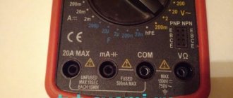
Measuring instruments
The most accessible method for measuring capacitance is a widely used multimeter with this capability.
In most cases, such devices have an upper measurement limit of tens of microfarads, which is sufficient for standard applications. The reading error does not exceed 1% and is proportional to the capacity. To check, just insert the capacitor leads into the intended sockets and read the readings; the whole process takes a minimum of time. This function is not present in all models of multimeters, but it is often found with different measurement limits and methods of connecting the capacitor. To determine more detailed characteristics of the capacitor (loss tangent and others), other devices are used, designed for a specific task, often stationary devices.
The measurement circuit mainly implements the bridge method. They are used limitedly in special professional areas and are not widely used.
Types of faults
The main malfunctions are the following:
- break - its cause may be an imperfect design, violation of operating conditions, shaking and vibration, mechanical damage;
- electrical breakdown - its cause is usually an increase in voltage above the permissible level;
- increased leakage - they are caused by a change in resistance between the plates of the capacitor, which makes it unable to retain charge and leads to a decrease in capacity.
Any of these reasons makes it impossible to further operate the capacitor and requires its replacement.
Sometimes a capacitor failure can be determined visually when the element is clearly different from similar ones (cracks, swelling, and electrolyte leaks may be visible on it). But a more reliable way to check functionality is to measure the capacity of the suspect device.
Before checking with a tester, you need to determine the type of device - a polar capacitor or a non-polar one. This can be determined by the mark on its body. If there is a black stripe on it indicating zero, then there is a negative contact on the side of this pin, and a positive contact on the opposite side.
Some testers have a capacitance measurement function. Moreover, they have special sockets where the capacitor leads are inserted.
Homemade C-meter
Without taking into account various exotic solutions, such as a ballistic galvanometer and bridge circuits with a resistance store, a novice radio amateur can make a simple device or an attachment for a multimeter. The widely used 555 series chip is quite suitable for these purposes. This is a real-time timer with a built-in digital comparator, in this case used as a generator.
The frequency of rectangular pulses is set by selecting resistors R1–R8 and capacitors C1, C2 using switch SA1 and is equal to: 25 kHz, 2.5 kHz, 250 Hz, 25Hz - corresponding to switch positions 1, 2, 3 and 4–8. The capacitor Cx is charged at a pulse repetition rate through the diode VD1, to a fixed voltage. The discharge occurs during a pause through resistances R10, R12–R15. At this time, a pulse is formed with a duration depending on the capacitance Cx (larger capacitance - longer pulse). After passing through the integrating circuit R11 C3, a voltage appears at the output corresponding to the pulse length and proportional to the value of the capacitance Cx. A multimeter (X 1) is connected here to measure voltage at a limit of 200 mV. The positions of switch SA1 (starting from the first) correspond to the limits: 20 pF, 200 pF, 2 nF, 20 nF, 0.2 µF, 2 µF, 20 µF, 200 µF.
Adjustment of the structure must be done with a device that will be used in the future. Capacitors for adjustment must be selected with a capacity equal to the measurement subranges and as accurately as possible, the error will depend on this. Selected capacitors are connected one by one to X1. First of all, the subranges of 20 pF–20 nF are adjusted; for this, the corresponding trimming resistors R1, R3, R5, R7 are used to achieve the corresponding multimeter readings; you may have to slightly change the values of the series-connected resistances. On other subranges (0.2 µF–200 µF) calibration is carried out with resistors R12–R15.
The wires connecting the resistors to the switch should be as short as possible, and if the design allows, they should be placed on its terminals. It is advisable to use multi-turn variables; it is better to use constant ones, but this is not always possible. It is necessary to thoroughly wash the printed circuit board from flux and other dirt, otherwise parasitic capacitances and resistance between conductors can lead to complete inoperability of the product.
When choosing a power source, it should be taken into account that the amplitude of the pulses directly depends on its stability. Integrated stabilizers of the 78xx series are quite applicable here. The circuit consumes a current of no more than 20–30 milliamps and a filter capacitor with a capacity of 47–100 microfarads will be sufficient. The measurement error, if all conditions are met, can be about 5%; in the first and last subranges, due to the influence of the capacitance of the structure itself and the output resistance of the timer, it increases to 20%. This must be taken into account when working at extreme limits.
TECHNICAL SPECIFICATIONS Ftike A6243L
| Key Features of the ESR Meter | |
| Capacitance measurement range | 2 nF, 20 nF, 200 nF, 2 µF, 20 µF in 1 pF steps, accuracy ± (1.5% + 5d) 20 µF, accuracy ± (2.0% + 5d) |
| Inductance measurement range | 2 mH, 20 mH, 200 mH in 1 μH steps, accuracy ± (2.0% + 5d) 2 H, 20 H ± (5.0% + 5d) |
| Components tested | polar and non-polar capacitors; inductors; chokes; |
| Hold data function | There is |
| General characteristics | |
| Display | LCD 1999 digits, 44 mm x 28 mm |
| Nutrition | DC 9 V, battery 6F22 "Krona" |
| Dimensions | 140 mm x 70.6 mm x 31 mm |
| Device weight | 200 g |
| Equipment | capacitor esr meter Ftike A6243L – 1 pc 6F22 “Krona” battery – 2 pcs probes with alligator clips – 1 pc |
Construction and details
R1, R5 6.8k R12 12k R10 100k C1 47nF
R2, R6 51k R13 1.2k R11 100k C2 470pF
R3, R7 68k R14 120 C3 0.47mkF
R4, R8 510k R15 13
Diode VD1 - any low-power pulsed, film capacitors, with low leakage current. The microcircuit is any of the 555 series (LM555, NE555 and others), the Russian analogue is KR1006VI1. The meter can be almost any voltmeter with a high input impedance, which is calibrated for it. The power source must have an output of 5–15 volts at a current of 0.1 A. Stabilizers with a fixed voltage are suitable: 7805, 7809, 7812, 78Lxx.
PCB option and component layout