Calculation of mixed connection of capacitors online. Calculation of a capacitor for LEDs
Transformerless power supplies with a quenching capacitor are convenient in their simplicity, have small dimensions and weight, but are not always applicable due to the galvanic connection of the output circuit with a 220 V network.
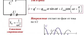
In a transformerless power supply, a series-connected capacitor and load are connected to an alternating voltage network. A non-polar capacitor connected to an AC circuit behaves like a resistance, but unlike a resistor, it does not dissipate the absorbed power as heat.
To calculate the capacity of the quenching capacitor, the following formula is used:
C is the capacitance of the ballast capacitor (F); Ieff - effective load current; f is the frequency of the input voltage Uc (Hz); Uc — input voltage (V); Un—load voltage (V).
For ease of calculations, you can use an online calculator
The design of transformerless sources and devices powered from them must exclude the possibility of touching any conductors during operation. Particular attention should be paid to insulating the controls.
29.09.2014
Operating frequency range 66...74 or 88...108 MHz Using R7, the separation between AF channels is adjusted. ***The signal is supplied from the output of the VHF (FM) frequency detector - receiver to the DA1 input through the correction circuit R1C1. Literature J. Radio Amateur 1 2000.
The need to connect an LED to the network is a common situation. This includes an indicator for turning on devices, a backlit switch, and even a diode lamp.
There are many schemes for connecting low-power indicator LEDs through a resistor current limiter, but such a connection scheme has certain disadvantages. If you need to connect a diode with a rated current of 100-150mA, you will need a very powerful resistor, the dimensions of which will be significantly larger than the diode itself.
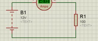
This is what the wiring diagram for a table LED lamp would look like. And powerful ten-watt resistors at low room temperatures could be used as an additional heating source.
The use of conductors as a current limiter allows one to significantly reduce the dimensions of such a circuit. This is what the power supply for a 10-15 W diode lamp looks like.
The principle of operation of circuits using a ballast capacitor
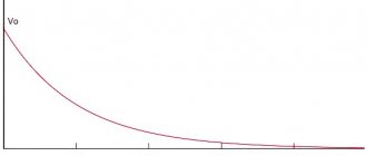
In this circuit, the condenser is a current filter. Voltage is supplied to the load only until the condenser is fully charged, the time of which depends on its capacity. In this case, no heat generation occurs, which removes restrictions on load power.
To understand how this circuit works and the principle of selecting a ballast element for an LED, let me remind you that voltage is the speed of electrons moving along the conductor, and current is the electron density.
For a diode, it is absolutely indifferent at what speed electrons will “fly” through it. The calculation of the conductor is based on the current limitation in the circuit. We can apply at least ten kilovolts, but if the current is several microamps, the number of electrons passing through the light-emitting crystal will be enough to excite only a tiny part of the light emitter and we will not see the glow.
At the same time, at a voltage of several volts and a current of tens of amperes, the electron flux density will significantly exceed the throughput of the diode matrix, converting the excess into thermal energy, and our LED element will simply evaporate in a cloud of smoke.
Calculation of a quenching capacitor for an LED
Let's look at the detailed calculation; below you can find the online calculator form.
Calculation of capacitor capacity for an LED:
C(uF) = 3200 * Isd) / √(Uin² - Uout²)
With uF
– condenser capacity.
It should be rated at 400-500V; Isd
– rated current of the diode (see the passport data);
Uin
– amplitude network voltage - 320V;
Uout
– rated LED supply voltage.
You can also find the following formula:
C = (4.45 * I) / (U - Ud)
It is used for low-power loads up to 100 mA and up to 5V.
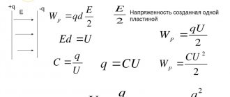
Parallel current
The capacitor current during the transition period depends on its capacitance and voltage change:
- ic — capacitor current
- C - Capacitance of the capacitor
- ΔVC/Δt – Rate of voltage change
In a parallel connection, a separate current will flow through each capacitor, depending on the capacitance of the capacitor:
Parallel current
Connection diagram for LED to 220 volt network
Light indication is an integral part of electronics, with the help of which a person can easily understand the current state of the device. In household electronic devices, the role of indication is performed by an LED installed in the secondary power circuit, at the output of the transformer or stabilizer.
However, in everyday life there are also many simple electronic designs that do not have a converter, in which an indicator would be a useful addition. For example, an LED built into a wall switch key would be an excellent reference for the location of the switch at night.
And the LED in the body of the extension cord with sockets will signal that it is connected to a 220 V power supply.
Below are several simple diagrams with which even a person with minimal knowledge of electrical engineering can connect an LED to an AC network.
Connection diagrams
An LED is a type of semiconductor diode with a supply voltage and current much lower than in a household electrical network. If connected directly to a 220 volt network, it will instantly fail. Therefore, the light-emitting diode must be connected only through a current-limiting element. The cheapest and easiest to assemble are circuits with a step-down element in the form of a resistor or capacitor.
An important point that you need to pay attention to when connecting an LED to an AC network is the reverse voltage limitation. This task can easily be accomplished by any silicon diode designed for a current no less than that flowing in the circuit. The diode is connected in series after the resistor or with reverse polarity in parallel with the LED.
There is an opinion that it is possible to do without limiting the reverse voltage, since electrical breakdown does not cause damage to the light-emitting diode. However, reverse current can cause the pn junction to overheat, resulting in thermal breakdown and destruction of the LED crystal.
Instead of a silicon diode, you can use a second light-emitting diode with a similar forward current, which is connected in reverse polarity in parallel with the first LED.
The downside to current-limiting resistor circuits is that they require a lot of power dissipation. This problem becomes especially relevant when connecting a load with a large current consumption. This problem is solved by replacing the resistor with a non-polar capacitor, which in such circuits is called ballast or quenching.
A non-polar capacitor connected to an AC network behaves like a resistance, but does not dissipate the power consumed in the form of heat.
In these circuits, when the power is turned off, the capacitor remains undischarged, which creates a risk of electric shock. This problem is easily solved by connecting a 0.5-watt shunt resistor with a resistance of at least 240 kOhm to the capacitor.
Calculation of a resistor for an LED
In all of the above circuits with a current-limiting resistor, the resistance is calculated according to Ohm's law: R = U/I, where U is the supply voltage, I is the operating current of the LED. The power dissipated by the resistor is equal to P = U * I. These data can be calculated using an online calculator.
Important. If you plan to use the circuit in a low-convection package, it is recommended to increase the maximum power dissipation value of the resistor by 30%.
You need to know this
The main thing is to remember safety precautions. The presented circuits are powered by 220 V AC, and therefore require special attention during assembly.
Connecting the LED to the network must be carried out in strict accordance with the circuit diagram. Deviation from the diagram or negligence can lead to a short circuit or failure of individual parts.
When you turn it on for the first time, it is recommended to let the assembly work for a while to make sure it is stable and does not overheat the elements.
To increase the reliability of the device, it is recommended to use previously tested parts with a margin of maximum permissible voltage and power values.
You should carefully assemble transformerless power supplies and remember that they do not have galvanic isolation from the network. The finished circuit must be reliably isolated from adjacent metal parts and protected from accidental contact. It can only be dismantled with the power supply switched off.
A little experiment
To lighten up the boring diagrams a little, we suggest that you familiarize yourself with a small experiment that will be of interest to both novice radio amateurs and experienced professionals.
Source: https://ledjournal.info/shemy/podklyuchenie-svetodioda-k-seti-220v.html
Resistive transformerless power supply
The circuit diagram of a typical transformerless resistive power supply is shown in the figure.
Again, the output voltage Vout remains constant as long as the current Iout is less than or equal to the input current Iin, the only difference being that the inrush current limiting is now implemented only by resistor R1. The output voltage Vout can be calculated using the same formula as for a capacitive power supply, and the input current Iin using the following formula:
As in the previous case, components must be selected with a power value at least twice the theoretical value that can be calculated by Ohm's law (P = R x I^2 for R1 and P = V x I for diodes D1 and D2) . Electrolytic capacitor C2 should be selected as for capacitive design.
The advantage of a resistive power supply is that it is smaller in size and weight compared to a transformer circuit and is the cheapest power supply solution. But even in this case there is no galvanic isolation from the AC network, and in addition, the efficiency is lower than in a capacitive solution.
How to connect an LED to 220V: diagrams, errors, nuances, video
Typically, LEDs are connected to 220V using a driver designed for their characteristics. But if you need to connect only one low-power LED, for example, as an indicator, then using a driver becomes impractical. In such cases, the question arises - how to connect the LED to 220 V without an additional power supply.
Basics of connecting to 220 V
Unlike the driver, which supplies the LED with direct current and a relatively low voltage (a few to tens of volts), the network produces an alternating sine-like voltage with a frequency of 50 Hz and an average value of 220 V. Since the LED passes current only in one direction, it will only glow on certain half-waves:
That is, the LED does not glow constantly with this power supply, but blinks at a frequency of 50 Hz. But due to the inertia of human vision, this is not so noticeable.
At the same time, a voltage of reverse polarity, although it does not cause the LED to glow, is still applied to it and can damage it if no protective measures are taken.
Methods for connecting an LED to a 220 V network
The easiest way (read about all possible ways to connect an LED) is to connect using a quenching resistor connected in series with the LED. It should be taken into account that 220 V is the rms value of U in the network. The amplitude value is 310 V, and must be taken into account when calculating the resistance of the resistor.
In addition, it is necessary to protect the light-emitting diode from reverse voltage of the same magnitude. This can be done in several ways.
Series connection of a diode with high reverse breakdown voltage (400 V or more)
Let's look at the connection diagram in more detail.
The circuit uses a 1N4007 rectifier diode with a reverse voltage of 1000 V. When the polarity is changed, all the voltage will be applied to it, and the led is protected from breakdown.
This connection option is clearly shown in this video:
It also describes how to determine the location of the anode and cathode of a standard low-power LED and calculate the resistance of the quenching resistor.
Capacitor for DC motor
The question seems to be simple. But I'm being stupid. And in the universal mind, somehow there is not a lot of information.
1. Does the capacitor still have any function? For example, to start the engine.
2. (and the most important) how to calculate the parameters of the capacitor (capacitance, reactive power)? In short, what kind of capacitor is needed for this motor?
Thanks in advance for your answers.
for the collector, ceramics of 0.1-10 uF are often hung, 3 pieces: 1 between the terminals, 2 more between each terminal and the housing
dimax, I agree, I didn’t say, I’m sorry: collector, controlled by pure voltage (confirmed by an oscilloscope), which comes from the driver, which, in turn, is controlled via PWM from the Mega arduino.
for the collector, ceramics of 0.1-10 uF are often hung, 3 pieces: 1 between the terminals, 2 more between each terminal and the housing
jeka_tm, thank you, but I want to understand and calculate what specific and most importantly what other characteristics should be at the specified engine parameters so that it does not rupture or overheat (I mean the capacitor).
I don't know such calculations. empirically
I don't know such calculations. empirically
those. look through the cracks: is there a spark/no spark?
There will be sparks anyway. these are brushes. the brush moves away from the contact, but the current cannot instantly stop flowing in the coil, induction occurs
but in general it’s funny how they write about the coil and the current))))
but in general it’s funny how they write about the coil and the current))))
Not really. try to understand from the text what is true and what is not
and how the coil is turned on and off (the brush slides along the contacts) an equal pulse signal is supplied to the coil
Explain to me, dark, how a capacitor will relieve collector sparking? What is physics? Theoretically, a capacitor on the rotor in parallel with the coils could reduce sparking and work as a snubber based on the appearance of bursts of self-induction. But what about the collector? Everything that is generated by the rotor coils must first pass through the collector (with sparking) and only then be extinguished by the capacitor
small capacitors as described above work as a filter for high-frequency interference, but do not affect sparking
small capacitors as described above work as a filter for high-frequency interference, but do not affect sparking
Understood thanks! Interferences are of little interest to me for now, but about starting the engine, if possible, in more detail. What is considered high capacity?
Understood thanks! Interferences are of little interest to me for now, but about starting the engine, if possible, in more detail. What is considered high capacity?
we are talking about thousands and tens of thousands of microfarads
It may not get rid of sparking, but it will short-circuit the alternating component that arises at the moment the contacts are released. The interference will be extinguished close to the point of origin, and not travel along the power supply circuits.
There were no problems at start-up.
But the air conditioner helped, clearly and fundamentally, and forgot about the problem altogether.
There was another interesting moment. Rebooted in the same way when reversing the engine. This moment after the condenser did not disappear, but was corrected programmatically, with a pause of only 50 ms. Those. turn off the engine, pause, turn it on in the other direction, I was surprised that such a small pause turned out to be significant.
It may not get rid of sparking, but it will short-circuit the alternating component that arises at the moment the contacts are released. The interference will be extinguished close to the point of origin, and not travel along the power supply circuits.
I write about Conder as an interference filter in my post just below your quote, but I agree with you that this is not about sparks
we are talking about thousands and tens of thousands of microfarads
The idea about the key is clear, although I didn’t get it right away! THANK YOU! I'll try to try. In terms of capacity, unfortunately, I suspected so. They no longer cost pennies, although they are not exorbitant.
Logik protective diodes for bridge connection (in your case via a relay) are hung on each arm, i.e. 4 pieces
Yes, at the same time they shorten the bursts on the power supply. This is normal if the power wires are correctly routed. a powerful load must have a source with low internal resistance; interference is not a problem for it, it “shorts” them to itself
It is better to minimize interference than to simply deal with its consequences
Logik protective diodes for bridge connection (in your case via a relay) are hung on each arm, i.e. 4 pieces
Yes, at the same time they shorten the bursts on the power supply. This is normal if the power wires are correctly routed.
Perhaps, of course, a diode + separate power supply + different connectors + new wires + maybe a second battery would also help. But one Conder seems to be better in all respects.
a powerful load must have a source with low internal resistance; interference is not a problem for it, it “shorts” them to itself
It is better to minimize interference than to simply deal with its consequences
Moreover, minimize it near the place of occurrence. This is what the Conder does on the engine.
Another point, if it’s not a relay but a transistor bridge, then you have to be careful with the condenser, it will heavily load the keys, but the relay will be tolerated.
I will allow myself a few simple theoretical arguments about the selection of a capacitor.
All reasoning will not be very quantitative and will be based on formulas from a school physics textbook and common sense.
1. Anti-interference capacitor. You need to know the frequency, amplitude and current of the interference.
2. You cannot install a very large capacitor, since the motor needs to be controlled. This is a limitation from below.
The nature of interference in the EDMC (Electro-Direct Current Motor) in switching the windings on the brush assembly.
The voltage on the coil when the current changes =L * dI/dt. The switching frequency is the number of revolutions per second multiplied by the number of commutator lamellas.
We already know everything: Inductance is no more than 12*2/200=120mH. Therefore, the interference amplitude is not higher than 0.120*2*1000=240V.
That is, the voltage of the capacitor should be 300-400V. Enough.
Connecting an LED to 220 volts, diagrams, examples (video, calculator)
When designing radio equipment, the question of power indication often arises. The age of incandescent lamps for indication has long passed; the modern and reliable radio indication element at the moment is the LED.
This article will propose a diagram for connecting an LED to 220 volts, that is, we will consider the possibility of powering the LED from a household AC network - an outlet that is found in any comfortable apartment. If you need to power several LEDs at the same time, we will also mention this in our article.
In fact, such circuits are used for LED garlands or lamps, this is a little different. In fact, here it is necessary to implement a so-called driver for LEDs. So, let's not lump everything together. Let's try to figure it out in order.
The principle of reducing the supply voltage for an LED
Two power paths can be selected to supply low voltage loads. The first is, so to speak, the classic version, when the power is reduced by a resistor. The second option, which is often used for chargers, is a quenching capacitor.
In this case, the voltage and current flow as if in pulses, and these same pulses must be precisely selected so that the LED and the load do not burn out. This requires a more detailed calculation than with a resistor. The third option is a combined power supply, when both methods of reducing voltage are used.
Well, now about all these options in order.
Connection diagram for LED to 220 volts (quenching capacitor)
The diagram for connecting an LED to 220 volts does not look complicated, the principle of its operation is simple. The algorithm is as follows. When voltage is applied, capacitor C1 begins to charge, while in fact, on one side it is charged directly, and on the other through a zener diode. The zener diode must match the LED voltage.
Thus, the capacitor is ultimately fully charged. Next comes the second half-wave, when the capacitor begins to discharge. In this case, the voltage also goes through the zener diode, which now operates in its normal mode and through the LED. As a result, a voltage equal to the stabilization voltage of the zener diode is supplied to the LED at this time.
Here it is important to choose a zener diode with the same rating as the LED.
Everything here seems to be simple and theoretically implemented normally. However, exact calculations are not so simple. After all, in fact, it is necessary to calculate the capacitance of the capacitor, which in this case will act as a damping one. This is done according to the formula.
Let's estimate: 3200*0.02/√(220*220-3*3)=0.29 mF. This is what the capacitor should be like if the LED voltage is 3 volts and the current is 0.02 A. You can substitute your values and calculate your option.
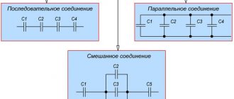
Parallel connection of capacitors
Parallel connection of capacitors is a connection in which the capacitors are connected by both contacts. As a result, several capacitors can be connected to one point.
When connected in parallel, one large capacitor is formed with a plate area equal to the sum of the plate areas of all individual components. Since the capacitance of capacitors is directly proportional to the area of the plates, the total capacitance Ctot in a parallel connection is equal to the sum of the capacitances of all capacitors in the circuit.
Parallel connection of capacitors
Calculation of a capacitor for LEDs. Capacitors
The need to connect an LED to the network is a common situation. This includes an indicator for turning on devices, a backlit switch, and even a diode lamp.
There are many schemes for connecting low-power indicator LEDs through a resistor current limiter, but such a connection scheme has certain disadvantages. If you need to connect a diode with a rated current of 100-150mA, you will need a very powerful resistor, the dimensions of which will be significantly larger than the diode itself.
This is what the wiring diagram for a table LED lamp would look like. And powerful ten-watt resistors at low room temperatures could be used as an additional heating source.
The use of conductors as a current limiter allows one to significantly reduce the dimensions of such a circuit. This is what the power supply for a 10-15 W diode lamp looks like.
Calculation of a capacitor for LEDs
The need to connect an LED to the network is a common situation. This includes an indicator for turning on devices, a backlit switch, and even a diode lamp.
There are many schemes for connecting low-power indicator LEDs through a resistor current limiter, but such a connection scheme has certain disadvantages. If you need to connect a diode with a rated current of 100-150mA, you will need a very powerful resistor, the dimensions of which will be significantly larger than the diode itself.
This is what the wiring diagram for a table LED lamp would look like. And powerful ten-watt resistors at low room temperatures could be used as an additional heating source.
The use of conductors as a current limiter allows one to significantly reduce the dimensions of such a circuit. This is what the power supply for a 10-15 W diode lamp looks like.
Connecting one LED
To calculate the capacity of the condenser we will need:
- Maximum diode current – 0.15A;
- diode supply voltage – 3.5V;
- amplitude voltage of the network - 320V.
For such conditions, the parameters of the condenser are: 1.5 µF, 400 V.
Connecting multiple LEDs
When calculating a capacitor for an LED lamp, it is necessary to take into account that the diodes in it are connected in groups.
- Supply voltage for a daisy chain – Usd * number of LEDs in the chain;
- current strength – Isd * number of parallel chains.
For example, let's take a model with six parallel lines of four series diodes.
Supply voltage – 4 * 3.5V = 14V; Circuit current – 0.15A * 6 = 0.9A;
For this circuit, the condenser parameters are: 9 μF, 400 V.