When designing electrical circuits, equipment and electrical appliances, many properties of conductors are taken into account. One of the important properties is capacitance.
This article will describe in detail what the capacitance of a capacitor is. A formula for calculating such a parameter will also be given, the operation of a capacitor in an alternating current circuit and the scope of application of capacitance will be described.
Definition
Resistance is the physical effect of opposing the flow of current through any electrical circuit. All conductors of electric current have this property. This value is measured in Ohms.
Capacitive electrical resistance is a value through which you can understand that there is a capacitor in the circuit. The capacitance of a capacitor is calculated only for alternating current circuits, without taking into account the presence of resistors in them.
The capacitor is designated in the diagram by the letter “C”, and its capacitance “Xc”.
Capacitance of a capacitor
Capacitors are among the most common elements used in various electronic circuits. They are divided into types that have characteristic features, parameters and individual properties. The simplest capacitor consists of two metal plates - electrodes, separated by a dielectric layer. Each of them has its own terminal through which the connection to the electrical circuit is made.
Capacitance can be classified as reactive, which does not cause irreversible energy losses. The capacitor is charged to the voltage level supplied by the power source.
In a completely different way, the capacitor is affected by alternating current, which flows quite freely through the capacitance. This condition is explained by the constant processes of charging and discharging the element. In this case, not only the active resistance of the conductors acts, but also the capacitive reactance of the capacitor itself, which arises precisely as a result of its constant charging and discharging.
The electrical parameters and properties of capacitors may vary depending on various factors. First of all, they depend on the size and shape of the product, as well as on the type of dielectric. In different types of devices, the dielectric can be paper, air, plastic, glass, mica, ceramics and other materials. Electrolytic capacitors use aluminum electrolyte and tantalum electrolyte, which provides them with increased capacity.
The names of other elements are determined by the materials of conventional dielectrics. Therefore, they fall into the category of paper, ceramic, glass, etc. Each of them, in accordance with the characteristics and features, is used in specific electronic circuits, with different electric current parameters.
In this regard, the use of ceramic capacitors is necessary in those circuits where high-frequency noise filtering is required. Electrolytic devices, on the other hand, filter out interference at low frequencies. If you connect both types of capacitors in parallel, you get a universal filter that is widely used in all circuits. Despite the fact that their capacitance is a fixed value, there are devices with variable capacitance, which is achieved by adjustments by changing the mutual overlap of the plates. A typical example is tuning capacitors used in tuning electronic equipment.
Principle of operation
A capacitor with a certain capacity operates on the principle of a period, which consists of charging and discharging an element. The period is divided into 4 parts:
- The first part involves increasing tension. At this moment, the capacitor resistance is minimal and the charging current is very high.
- In the second quarter, its capacity is filled due to the charging current.
- In the third quarter, the capacitor is fully charged, and the current decreases down to 0. The EMF increases with the effect of changing its direction.
- In the last quarter the element is discharged. At this stage, the EMF will be within 0, and the current will gradually increase.
All the processes described in one period determine a further phase shift of 90 degrees.
The nature of the occurrence of capacitance depends entirely on several factors:
- It is necessary to have a capacitor in the circuit.
- Only alternating current should flow through the circuit.
- The conductor resistance must be less than the capacitance of the capacitor.
All these factors help to calculate the most correct value of capacitance characteristics for the most efficient operation of the electrical circuit.
general description
Physically, an electronic device - a capacitor - consists of two plates made of conductive material, between which there is a dielectric layer. Two electrodes are removed from the surface of the plates, intended for connection to an electrical circuit. Structurally, the device can be of different sizes and shapes, but its structure remains unchanged, that is, there is always an alternation of conductive and dielectric layers.
The word “capacitor” comes from the Latin “condensatio” - “accumulation”. The scientific definition states that a storage electrical device is a two-terminal device characterized by constant and variable capacitance values and high resistance. It is designed to store energy and charge. The unit of measurement of capacitance is the farad (F).
In the diagrams, the capacitor is depicted as two straight lines, corresponding to the conducting plates of the device, and drawn perpendicular to their centers by drawn segments - the terminals of the device.
The principle of operation of a capacitor is as follows : when the device is connected to an electrical circuit, the voltage in it will have a zero value. At this moment, the device begins to receive and accumulate charge. The electric current supplied to the circuit will be the maximum possible. After some time, positive charges will begin to accumulate on one of the electrodes of the device, and negative charges on the other.
The duration of this process depends on the capacitance of the device and the active resistance. The dielectric located between the terminals prevents the movement of particles between the plates. But this will happen only until the potential difference of the power source and the voltage at the capacitor terminals are equal. At this moment, the capacity will become maximum possible, and the electric current will be minimal.
If voltage is no longer supplied to the element, then when a load is connected, the capacitor begins to transfer its accumulated charge to it. Its capacity decreases, and the voltage and current levels in the circuit decrease. In other words, the storage device itself turns into a power source. Therefore, if a capacitor is connected to alternating current, it will begin to periodically recharge, that is, create a certain resistance in the circuit.
Calculation
The calculation of the electrical capacitance of the circuit is done according to the formula. It consists of the following values:
- "Xc" is the capacitance in Ohms.
- “1” is the period of complete charge and discharge of the element.
- “w” is the circular frequency of alternating current with capacitance, rad/sec.
- “C” is the capacitance of the capacitor, units of Farad.
The formula itself looks like this:
Using this formula, Xc can be easily calculated. To do this, simply multiply the cyclic frequency of the alternating current by a known capacitor value. Next, you will need to divide one period by the resulting value. This way you can always find the resistance of the capacitor in Ohms.
Capacitance can also be calculated using another formula, which is shown in the figure below.
When calculating using this formula, the following dependencies can be traced:
- The capacitance of the capacitor and the frequency of the current are always higher than the resistance.
- The speed of one period of charge/discharge of the capacitor depends on the values of capacitance and frequency.
It is also worth considering that after connecting a capacitor to a DC circuit, its resistance increases greatly. The reason for this phenomenon is explained quite simply - there is no frequency of electricity flow.
Alternating current
Gentlemen, today’s article can be considered in some way a continuation of the previous one. At first I even wanted to put all this material in one article. But it turned out to be quite a lot, there were new projects on the horizon, and I ended up splitting it into two. So, today we will talk about the resistance of a capacitor to alternating current
. We will obtain an expression by which we can calculate the resistance of any capacitor connected to an alternating current circuit, and at the end of the article we will consider several examples of such calculations.
I’ll immediately mention one important thing. Generally speaking, a real capacitor has, in addition to capacitive
resistance is also
resistive
and
inductive
.
In practice, all this must be taken into account, because situations are possible (usually associated with an increase in the signal frequency) when the capacitor ceases to be a capacitor and turns... into some kind of inductor. When designing circuits, this point must be kept in mind. Agree, gentlemen, it is extremely unpleasant to put a capacitor in a circuit and then face the fact that, due to the high frequency, it behaves not like a capacitor at all, but like a real inductor. This is, of course, a very important topic, but today we will not talk about it. In today's article we will talk directly about capacitance
of a capacitor. That is, we will consider it ideal, without any parasitic parameters such as inductance or active resistance.
Let's imagine that we have a capacitor that is connected to an alternating current circuit. There are no more components in the circuit, just one capacitor and that's it (Figure 1).
Figure 1 – Capacitor in an AC circuit
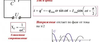
Some alternating voltage U(t) I(t) flows through it . Knowing one, you can easily find another. To do this, you just need to remember the previous article about a capacitor in an alternating current circuit, where we talked about all this in some detail. We will assume that the current through the capacitor varies according to a sinusoidal law like this
In the last article we came to the conclusion that if the current changes according to this law, then the voltage on the capacitor should change as follows
So far we have not recorded anything new; this is all a verbatim repetition of calculations from the previous article. And now is the time to transform them a little, give them a slightly different look. To be specific, we need to move on to a complex representation of signals! Remember there was a separate article on this topic? In it I said that it is needed to understand some points in further articles. The moment has just come when it’s time to remember all these cunning imaginary units. To be specific, now we need an indicative
writing a complex number. As we remember from the article about complex numbers in electrical engineering, if we have a sinusoidal signal of the form
then it can be represented in exponential form like this
Why this is so, where it came from, what the letter means here - everything has already been discussed in detail. To repeat, you can follow the link and read everything again.
Let's now apply this complex representation to our capacitor voltage formula. We'll get something like this
Now, gentlemen, I would like to tell you about one more interesting point, which probably should have been described in an article about complex numbers in electrical engineering. However, I somehow forgot about it at the time, so let's look at it now. Let's imagine that t=0 . This will lead to the exclusion of time and frequency from the calculations, and we move on to the so-called complex amplitudes
signal.
Of course, this does not mean that the signal changes from variable to constant. No, it still continues to change in the sine direction with the same frequency. But there are times when the frequency is not very important to us, and then it is better to get rid of it and work only with amplitude
.
Now is just such a moment. Therefore, we set t=0 and get the complex voltage amplitude.
Let's open the brackets in the exponential and use the rules for working with exponential functions.
So we have three factors. We will deal with everything in order. Let's combine the first two and write the following expression
What did we even write down? That's right, the complex amplitude of the current
through a capacitor. Now the expression for the complex voltage amplitude takes the form
The result we are striving for is already close, but there remains one more not very pleasant exponential factor. What to do with him? And it turns out it’s very simple. And again, an article on complex numbers in electrical engineering will come to our aid; it’s not for nothing that I wrote it. Let's transform this factor using Euler's formula:
Yes, this whole tricky exponent with complex numbers in the exponent turns into just an imaginary one, preceded by a minus sign. I agree, it may not be so easy to realize this, but nevertheless, mathematics says that it is so. Therefore, our resulting formula takes the form
Let's express the current from this formula and bring the expression to a form corresponding to Ohm's law. We get
As we remember from the article about Ohm's law, our current was equal to voltage divided by resistance. So, it’s almost the same here! Well, except that our current and voltage are variable and are represented through complex amplitudes. In addition, do not forget that the current flows through the capacitor. Therefore, the expression that appears in the denominator can be considered as the capacitive
resistance of the capacitor to alternating current
:
Yes, the expression for the capacitor resistance looks like this. It is, as you can see, complex.
.
This is evidenced by the letter j in the denominator of the fraction. What does this complexity mean? What does it influence and what does it show? And it shows, gentlemen, only a phase shift of 90 degrees
between the current and voltage on the capacitor.
Namely, the current is 90 degrees ahead of the voltage. This conclusion is not news to us; all this was described in detail in the previous article. In order to better understand this, we must now mentally go from the resulting formula up to the moment where this j arose for us. As you climb, you will see that the imaginary unit j arose from Euler's formula due to the fact that there was a component there.
Our Euler formula arose from a complex representation of a sinusoid. And in the original sinusoid there was precisely a phase shift of 90 degrees of current relative to voltage. Something like this. It seems that everything is logical and nothing unnecessary has arisen. Now two completely logical questions may arise: how to work with such a representation and what are its benefits? And in general, so far there are only some wildly abstract letters and it’s not clear at all how to take and evaluate the resistance of a specific capacitor that we bought in a store and plugged into the circuit. Let's figure it out gradually.
As we have already said, the letter j in the denominator only tells us about the phase shift of current and voltage. But it does not affect the amplitudes of current and voltage. Accordingly, if the phase shift does not interest us
, then we can exclude this letter from consideration and obtain a simpler expression absolutely without any complexity:
Agree, life has become a little easier. This expression allows you to calculate the capacitor resistance for a specific capacitance and signal frequency. Please note, gentlemen, an interesting fact. The resistance of a capacitor, it turns out, depends not only on the capacitor itself (namely its capacitance), but also on the frequency of the flowing current.
If we recall ordinary resistors, then in them the resistance depended only on the resistor itself, material, shape and all that other stuff, but did not depend on frequency (of course, we are now talking about ideal resistors, without any parasitic parameters). Everything is different here. The same capacitor at different frequencies will have different resistance and current of different amplitudes will flow through it at the same voltage amplitude.
What else can we tell by looking at this formula? For example, the higher the signal frequency, the lower the capacitor resistance for it. And the larger the capacitance of the capacitor, the lower its resistance to alternating current.
By analogy with resistors, the resistance of capacitors is still measured in Ohms. However, you should always remember that this is a slightly different resistance, it is called reactive
.
And it is different primarily because of that notorious j in the denominator, that is, because of the phase shift. “Ordinary” (which are called active
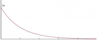
) Ohms do not have such a shift; there the voltage is clearly in phase with the current. Let's plot a graph of capacitor resistance versus frequency. To be specific, let’s take the capacitor capacitance as fixed, say, 1 µF. The graph is presented in Figure 2.
Figure 2 (clickable) – Dependence of capacitor resistance on frequency
In Figure 2 we see that the capacitor's resistance to alternating current decreases according to the hyperbola law.
As the frequency approaches zero
(that is, in fact, as the alternating current tends to direct), the resistance of the capacitor tends to infinity. This is logical: we all remember that for direct current, a capacitor is actually an open circuit. In practice, it is, of course, not infinite, but limited by the leakage resistance of the capacitor. However, it is still very large and is often considered infinitely large.
As the frequency approaches infinity
, the capacitor's resistance tends to zero. This is all in theory, of course. In practice, a real capacitor has a number of parasitic parameters (in particular, parasitic inductance and leakage resistance), due to which the resistance decreases only up to a certain frequency, and then begins to increase on the contrary. But more on this another time.
There is one more issue that I would like to discuss before starting to look at the examples. Why even write the letter j in the denominator of resistance? Isn’t it enough to just always remember about the phase shift, and use numbers without this imaginary unit in the recording? It turns out not. Let's imagine a circuit where a resistor and a capacitor are present at the same time. Let's say they are connected in series. And this is where the imaginary unit next to the capacitance will not allow you to simply add up the active and reactance into one real number. The total resistance of such a chain will be complex, consisting of both a real part and an imaginary part. The real part will be due to the resistor (active resistance), and the imaginary part will be due to the capacitance (reactance). However, this is all a topic for another article; we won’t go into it now. Let's move on to examples.
Let us have a capacitor with a capacity, say C=1 µF . It is required to determine its resistance at frequency f1=50 Hz and at frequency f2=1 kHz . In addition, the amplitude of the current should be determined taking into account the fact that the amplitude of the voltage applied to the capacitor is Um=50 V. Well, build graphs of voltage and current.
Actually, this task is elementary. We substitute the numbers into the formula for resistance and get for frequency f1=50 Hz a resistance equal to
And for frequency f2=1 kHz the resistance will be
Using Ohm's law, we find the current amplitude for frequency f1=50 Hz
Similarly for the second frequency f2=1 kHz
Now we can easily write down the laws of change in current and voltage, and also draw graphs for these two cases. We believe that our voltage changes according to the sine law for the first frequency f1=50 Hz as follows
And for the second frequency f2=1 kHz like this
Next, we remember that the current in the capacitor leads the voltage by .
Therefore, taking this into account, we can write down the law of change in current through capacitors for the first frequency
f1=50 Hz
and for frequency f2=1 kHz
Current and voltage graphs for frequency f1=50 Hz are presented in Figure 3
Figure 3 (clickable) – Voltage on the capacitor and current through the capacitor, f1=50 Hz
Graphs of current and voltage for frequency f2=1 kHz Hz are presented in Figure 4
Figure 4 (clickable) – Voltage on the capacitor and current through the capacitor, f2=1 kHz
So, gentlemen, today we became acquainted with such a concept as the resistance of a capacitor to alternating current, learned to calculate it and reinforced the acquired knowledge with a couple of examples. That's all for today. Thank you for reading, great luck everyone and bye!
Join our VKontakte group
Questions and suggestions to the admin: This email address is being protected from spambots. You need JavaScript enabled to view it.
Social button for Joomla
Item characteristics
In order to understand what capacitance is, it is necessary to understand its main characteristic, which is called capacitance. Capacity is the storage capacity of an element. It consists in the accumulation of a certain proportion of electric current over a certain period of time. The unit of measurement for this quantity is Farad (F or F).
The element is charged with electricity up to a certain point, after which it begins to discharge and release current further along the electrical circuit. The time for complete discharge directly depends on the value of the circuit resistance. The higher this value, the less time is spent discharging the element. To calculate the capacitance characteristic, the following expression is used:
Capacitors also have a number of additional characteristics. These include:
- Total specific capacitance. It is the ratio of the mass of dielectric plates and capacitive parameters.
- Voltage. The parameter is defined as the operating voltage that the element can withstand.
- Temperature resistance or stability. This is a temperature parameter that does not affect the change in capacitance.
- Insulation resistance. Is the value of the leakage point and self-discharge.
- Equivalent load. A value that defines the loss at the output or contacts of the device.
- Absorption. Potential difference at the moment of discharge to 0.
- Polarity. The parameter is characteristic of elements that operate strictly when a potential of a certain value (plus or minus) is applied to the plate.
- Inductance. The property of a capacitor to form inductive reactance at the contacts. This property can provide the element with the parameters of an oscillatory circuit.
All these values are strictly taken into account when designing circuits or circuits of electrical equipment.
Unit and calculation formulas
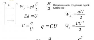
Capacitance, an electrical property capable of storing charges, is measured in farads (F) and is designated C. The value is named after the English physicist Michael Faraday. A capacitor with a capacity of 1 farad is capable of storing a charge of 1 coulomb on the plates with a voltage of 1 volt. The value of C is always positive.
Mathematical expression for farad
The capacitance of a capacitor is a constant value indicating the potential ability to store energy. The amount of charge stored at any given moment is determined by the equation Q=CV, where V is the applied voltage. Thus, by adjusting the voltage on the plates, the charge can be increased or decreased. This capacitance formula in the form C=Q/V in unit values determines how the capacitance of a capacitor is measured in SI and is the mathematical expression for the farad.
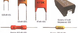
Electronics experts consider the unit of one farad not very practical, since it represents a huge value. Even 1/1000 F is a very large capacity. Typically, the following values are used for actual electrical components:
- picofarad - 10-12 F;
- nanofarad - 10-9 F;
- microfarad - 10-6 F.
You might be interested in the material from which the artificial ground electrode should be made
The dielectric constant
The factor by which an insulator determines the capacitance of a capacitor is called dielectric constant. The generalized formula for calculating the capacitance of a parallel plate capacitor is represented by the expression C= ε (A / d), where:
- A is the area of the smaller plate;
- d is the distance between them;
- ε is the absolute permeability of the dielectric material used.
The dielectric constant of vacuum ε0 is a constant and has a value of 8.84x10⁻¹² farads per meter. Typically, the conductive plates are separated by a layer of insulating material rather than a vacuum. To find the capacitance of a capacitor whose plates are in the air, you can use the value ε0. The difference in dielectric constant of the atmosphere and vacuum can be neglected, since their values are very close.
In practice, formulas for finding the capacitance of a capacitor use relative dielectric constant as a coefficient, meaning how much the electric field between charges decreases in a dielectric compared to a vacuum. Some values of this value for various materials:
- 1.0006 - air;
- 2.5—3.5 — paper;
- 3—10 — glass;
- 5-7 - mica.
Since the efficiency of a capacitor depends on the insulator used in it, its quality as a storage device can be determined through its specific capacitance - a value equal to the ratio of the capacitance to the volume of the dielectric.
Impedance
In addition to capacitance, a capacitor also has a total resistance or impedance. This value is determined taking into account the values of three parameters: inductive, resistive and capacitive reactance.
The following formula is used to calculate impedance:
The following resistances are used in this expression:
- xL - inductive;
- xC - capacitive;
- R - active.
The active resistance of the circuit appears due to the occurrence of EMF in it. Since alternating current is pulsed in nature, the electromagnetic flux can change quite slightly, and this leads to a shift in the constant value of the emf.
Capacitive and inductive quantities are interrelated. Based on the difference between them, the reactive component of the circuit can be easily found.
From here it is easy to see what the reactance itself depends on:
- If the reactive value is greater than 0, then the device is more loaded with the inductive value.
- If the reactive value is 0, then the capacitance is not loaded with active resistance.
- If the reactivity is less than 0, then the element has high capacitance.
Active resistance is considered an irreplaceable value. It is spent on converting current into another type of energy. The reactive quantity is unchanged for the actual AC circuit.
Practical uses of reactance
With the help of capacitor units, reactive power compensation is carried out. High-voltage electricity is transmitted over long distances through electrical networks. In most cases, it is consumed by electric motors with resistive elements and significant inductive reactance.
The total power supplied to consumers includes the active component P, with the help of which useful work is performed, and the reactive component Q, which leads to heating of the windings of electric motors and transformers. The quality of electricity is significantly reduced under the influence of the reactive component arising from inductive reactances. In order to eliminate its negative impact, a special compensation scheme was developed. For this purpose, capacitor banks were connected, the capacitance of which helped to reduce the cosine of the angle f.
The installation of such capacitor banks was practiced mainly at substations that directly supply electricity to problem consumers. This event made it possible to effectively regulate the quality of supplied energy.
Reducing the level of the reactive component helps to significantly reduce the load on installed equipment, although the active power remains at the same level. Using the reactance of a capacitor, it was possible to achieve energy savings at industrial production enterprises and housing and communal services facilities, and to increase the reliability of energy systems.
Calculation
Having found out what formula is used to make the necessary calculations and understanding the meaning of capacitance, you can start calculating this value.
For example, let's make a calculation based on the following data:
- Capacitance of the capacitor C=1uF;
- The circuit also has an active resistance R, which is equal to 5 kOhm;
- The inductive reactance of the xL circuit is 4.5 kOhm;
- AC frequency is 50 Hz;
- Voltage 50 volts.
Based on these data, it will be necessary to find the resistance of the capacitor.
We define capacitance as follows:
xC=1/(2πfC)=1/(2×3.14×50×1×10-6)=3184 Ohm or rounded 3.2 kOhm.
To determine the current value in this circuit, we use Ohm’s law:
I=U/xC=50/3184=0.0157 ampere or 15.7mA.
After this, the parameters of the total resistance are determined:
Z=(R²+(xL-xC)²)½=(5000²+(4500–3184)²)½=5170 Ohm or 5.1 kOhm.
According to these calculations, it is possible to determine the influence of the capacitive element on the electrical circuit. The main thing is to understand what physical quantities are used in these formulas to perform correct calculations.
Where is ESR hidden in a capacitor?
ESR is the resistance of the leads and plates
As you know, the resistance of a conductor can be found using the formula:
Where
ρ is the resistivity of the conductor
l - conductor length
S is the cross-sectional area of the conductor
So you can approximately calculate the resistance of the capacitor’s terminals and at the same time its plates. But, of course, no one does that. For this purpose, there are special devices that can measure this very parameter. For example, my device from Aliexpress, which I recently purchased.
Application
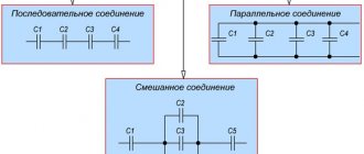
In electronic circuits, a capacitor is very often used as a filter element. In this case, engineers take into account the method of connecting this element:
- When a capacitor is connected in parallel to a circuit, the device is capable of blocking high frequency current. This filter operates on the principle that resistance depends on current frequency. The higher the frequency, the lower the resistance will be.
- When switched on in series, the filter already filters out low-frequency pulses. The second property of such a filter is the ability to prevent direct current from passing through.
Also, a large share of the use of such devices is for audio amplifiers. The capacitor is able to separate alternating and direct current, and therefore work as a low-frequency amplifier. In this case, elements with the smallest capacity are selected.
The devices are also used for DC power supplies or stabilizers. Here the property of separating the constant and variable components is applied. For example, dividing it between consumers using separate outputs for direct and alternating current. In such devices, the capacitor discharges if the load on the circuit is increased by connecting a new device. Thus, the overall ripple in the circuit is smoothed out. If necessary, current of both values can be transmitted through one conductor. This is done as follows - contacts with constant voltage are connected to the terminal of the capacitor for direct contact with alternating voltage. In this way, frequency filtering occurs, pulses are smoothed, and direct current is transferred to the consumer. This circuit is used in antenna amplifiers that are connected to televisions.
Capacitance of a capacitor
Capacitors are among the most common elements used in various electronic circuits. They are divided into types that have characteristic features, parameters and individual properties. The simplest capacitor consists of two metal plates - electrodes, separated by a dielectric layer. Each of them has its own terminal through which the connection to the electrical circuit is made.
There are qualities unique to capacitors. For example, they do not allow direct current to pass through them at all, although they are charged by it. After the container is fully charged, the current flow stops completely, and the internal resistance of the device takes on an infinitely high value.
The capacitor is affected in a completely different way by flowing quite freely through the capacitance. This condition is explained by the constant processes of charging and discharging the element. In this case, not only the active resistance of the conductors acts, but also the capacitive reactance of the capacitor itself, which arises precisely as a result of its constant charging and discharging.
The electrical parameters and properties of capacitors may vary depending on various factors. First of all, they depend on the size and shape of the product, as well as on the type of dielectric. Different types of devices can be paper, air, plastic, glass, mica, ceramics and other materials. Electrolytic capacitors use aluminum electrolyte and tantalum electrolyte, which provides them with increased capacity.
The names of other elements are determined by the materials of conventional dielectrics. Therefore, they fall into the category of paper, ceramic, glass, etc. Each of them, in accordance with the characteristics and features, is used in specific electronic circuits, with different electric current parameters.
In this regard, the use of ceramic capacitors is necessary in those circuits where high-frequency noise filtering is required. Electrolytic devices, on the other hand, filter out interference at low frequencies. If you connect both types of capacitors in parallel, you get a universal filter that is widely used in all circuits. Despite the fact that their capacitance is a fixed value, there are devices with variable capacitance, which is achieved by adjustments by changing the mutual overlap of the plates. A typical example is tuning capacitors used in tuning electronic equipment.
Measurement and testing
You can measure the integrity of the capacitor and its resistance using a multimeter. Before this, the element must be disconnected from the circuit.
Examination
Diagnosis of the integrity of the capacitor begins with a visual inspection of its condition. Any cracks, swelling or deformation of the housing can be considered a malfunction of the element. If a visual inspection does not produce any results, then the element is checked for breakdown using a tester.
This check is done as follows:
- The element must be removed from the circuit, and its contact terminals must be shorted with a metal object for discharge.
- Set the multimeter to resistance measurement mode.
- Connect the measuring probes to the contacts of the device.
- The resistance of a serviceable element will be measured at an infinite value, which will exceed the leakage resistance value. The magnitude of this leakage is 2 kOhm.
If the reading is less than this value, then the element is faulty and broken.
Metering
You can also measure resistance using a multimeter. It will need to be switched to the mode for measuring resistances of more than 100 kOhm. Next, you need to connect the probes of the device to the contacts of the device. It will take some time to fully charge the cell. After that, it will show the final result, which should not be higher than 100 kOhm. If this threshold is exceeded, then an unambiguous conclusion can be made that the element is faulty.
Capacitance measurement
To measure capacity, you will need a tester with CX mode. If there is no such mode, it will be impossible to check the element. Next is required:
- Completely discharge the capacitor.
- The CX mode is selected on the multimeter.
- Connect the measuring probes to the contact terminals of the device, strictly observing the polarity.
- The device must show a value greater than 1, but its value must be within the limits of those indicated on the body of the part. If the value is 0 or outside the specified values, then the capacitor can be considered faulty.
The data obtained by the multimeter can also be considered a capacitive value, since at the time of testing the element is charged with current.
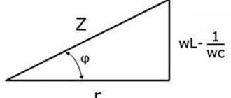
Vector diagram of currents in a circuit with a capacitor
To determine the effective value of the total current I using the vector addition method, we construct a vector diagram according to the equation
I = IG + IC
Effective values of current components:
IG = GU (13.31)
IC = BCU (13.32)
The first on the vector diagram is the voltage vector U (Fig. 13.16, a), its direction coincides with the positive direction of the axis from which the phase angles are measured (initial voltage phase φa = 0). Vector IG coincides in direction with vector U, and vector IC is directed perpendicular to vector U with a positive angle. From the vector diagram it can be seen that the total voltage vector lags behind the total current vector by an angle φ, the value of which is greater than zero, but less than 90º. Vector I is the hypotenuse of a right triangle, the legs of which are its constituent vectors IG and IC:
At voltage u = Umsinωt, according to the vector diagram, the current equation
i = Imsin(ωt + φ)
ESR electrolytic capacitors
Basically, the ESR parameter concerns electrolytic capacitors. The electrolyte that is there loses some of its properties when heated and the capacitor changes its capacity, which, of course, is undesirable. After decent heating, the capacitor begins to dull, swells and quickly ages.
For swollen capacitors, it is the ESR that first of all increases, while the capacitance can remain practically nominal until a certain time (well, the one that is written on the capacitor itself)
Most often they swell in switching power supplies and on motherboards, usually near the processor (the load on them is higher there, and the heat from the processor probably plays a role). One of the characteristic symptoms: equipment (computer, monitor) begins to turn on worse and worse. Either with a pause (up to several hours after turning on the network), or on the tenth attempt.
Another symptom: if you turn off the power for a while (turn off the power filter, or unplug it from the socket), it starts to turn on again, not on the first try, or after a pause. And if you do not turn off the power, then the computer can turn on immediately (but this is also for the time being, of course). But it happens that the capacitors are not swollen, and the ESR is already tens of times higher than normal. Then, of course, we replace it. From experience, this is a very common problem. And very easily diagnosed (especially if you have a miracle device from your Chinese comrades).