After closing the electrical circuit, charging begins, after which the capacitor immediately becomes a source of current and voltage, and an electromotive force - EMF - arises in it. One of the main properties of a capacitor is very accurately reflected by the capacitance formula. This phenomenon occurs as a result of counter-EMF directed against the current source used for charging. The current source can overcome capacitance only by significant expenditure of its own energy, which becomes the energy of the electric field of the capacitor. When the capacitor discharges, all the energy is returned back to the circuit, turning into electric current energy.
How is capacitive electrical resistance measured?
R is represented by the ratio of voltage to current in a closed electrical circuit, according to Ohm's law. Units of measurement are Ohms. Xc, as its variant, is also measured in Ohms.
Capacitors are used in the manufacture of filters. When connected in parallel to a circuit, it is capable of delaying high frequencies, and when connected in series, it removes low frequencies. They are also used to cut off the variable part from the constant part. It is indispensable in radio engineering, in the production of proximity sensors, and for monitoring production processes. Technologies with the properties described above are used in all areas of industry.
In alternating current circuits the following types of resistance are distinguished.
Active . The resistance of a resistor is called active. Symbol
The unit of resistance is Ohm. The resistance of the resistor does not depend on frequency.
Reactive . In the reactive section, three types of resistance are distinguished: inductive xL and capacitive xc and reactive itself. For the inductive reactance, the formula XL = ωL was obtained above. The unit of inductive reactance is also Ohm. The xL value depends linearly on frequency.
For the capacitance above, the formula XC = 1 / ωC was obtained. The unit of capacitance is Ohm. The value of xc depends on the frequency according to an inversely proportional law. Simply the reactance of a circuit is called the value X = XL - XC.
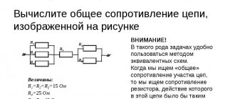
Total resistance . The total resistance of a circuit is called the quantity
.
From this relationship it follows that the resistances Z, R and X form a triangle: Z is the hypotenuse, R and X are the legs. For convenience, in this triangle we consider the angle φ, which is determined by the equation
and is called the phase shift angle. Taking this into account, additional connections can be made
Methods of connecting elements
Mounting the product on the board can be vertical or horizontal. When using several products, they can be connected to each other in different ways.
Parallel connection
To organize it, you need to connect a group of parts to an electrical circuit so that the plates of all parts are connected directly to the switching points. Since all components receive charge from the same current source, they will have the same potential difference. But since the charge accumulates on each product separately, the amount of electricity on the group can be expressed as the sum of the quantities on its parts.
This is also true for capacitive data - the value for the configuration is equal to the sum of the values of each unit. Therefore, such a group can be considered equal to one capacitor, the capacitive parameter of which is equal to the sum of those for all parts.
Serial connection
This scheme involves connecting devices one after another, when only the two outermost products are connected to the connection points in the circuit. The amount of electricity for each part will be the same. In this case, the less capacitive the device, the higher the voltage value will be observed on it.
Important! The capacitance value of such a system will be even less than that of a device with the lowest value. The relationship looks like this: 1/C = 1/C1 + 1/C2 + 1/C3 + ... Based on it, we can directly derive formula C. For two elements: C = C1*C2 / C1+C2.
Serial connection
Mixed compound
Such a complex structure contains fragments with the above two types of connections. To calculate the total capacity, the circuit is divided into simple blocks, consisting only of parts connected in one way. Find equivalent values for each block and then draw the diagram again in a simplified form. Calculate data for the resulting system.
To be able to select a suitable capacitor set, you need to be able to find out the capacitance data. It is also important to know how the indicator is calculated for a configuration of several parts connected to each other in one way or another.
What's happened
A circuit through which an intermittent current flows has total resistance. It is calculated by the sum of active and reactive resistance squared.
The graphic representation of this formula is a triangle. Its legs are represented by active and reactive resistance, and the hypotenuse is represented by total electrical resistance.
Capacitive electrical resistance (Xc) is one of the types of reactance. This indicator characterizes the resistance of the electrical capacitance in the circuit to electric current with variable parameters. The conversion of electricity into heat does not occur at the moment electricity flows through the container (reactance property). Instead, the energy of the electric current is transferred to the electric field and vice versa. There is no loss of energy during such an exchange.
The capacitance of a capacitor can be compared to a pan filled with liquid; when its volume is completely filled, it turns over, pouring out the contents, and then fills again. After reaching the maximum charge of the capacitor, it is discharged, then it is charged again.
Additional information: A circuit capacitor can only store a limited amount of charge before reversing the voltage polarity. For this reason, intermittent current does not drop to zero, an important difference from direct electricity. Low values of current frequency correspond to low values of charge accumulated by the capacitor, low values of resistance to electricity, which gives reactive properties.
Joule-Lenz law
The Joule-Lenz law states: the amount of heat released in a conductor in a section of an electrical circuit with resistance $R$ when a direct current $I$ flows through it for a time $t$ is equal to the product of the square of the current and the resistance and time:
$Q=I^2Rt$
The law was established in 1841 by the English physicist J. P. Joule, and in 1842 it was confirmed by the precise experiments of the Russian scientist E. H. Lenz. The very phenomenon of heating a conductor when current passes through it was discovered back in 1800 by the French scientist A. Fourcroy, who managed to heat an iron spiral by passing an electric current through it.
From the Joule-Lenz law it follows that when conductors are connected in series, since the current in the circuit is the same everywhere, the maximum amount of heat will be released on the conductor with the greatest resistance. This is used in technology, for example, for spraying metals.
In a parallel connection, all conductors are under the same voltage, but the currents in them are different. From the formula ($Q=I^2Rt$) it follows that, since, according to Ohm’s law, $I={U}/{R}$, then
$Q={U^2t}/{R}$
Therefore, more heat will be generated on a conductor with less resistance.
If in the formula ($A=IUt$) we express $U$ in terms of $IR$, using Ohm's law, we obtain the Joule-Lenz law. This once again confirms the fact that the work of the current is spent on heat generation at the active resistance in the circuit.
Instantaneous power in an alternating current circuit with active resistance.
With variable voltage and current values, the rate of conversion of electrical energy in the receiver, i.e. its power, also changes. Instantaneous power is equal to the product of instantaneous voltage and current values: p = Umsinωt * Imsinωt = UmImsin2ωt
From trigonometry we find
A more clear idea of the nature of the change in power in a circuit is given by a graph in a rectangular coordinate system, which is constructed after multiplying the ordinates of the voltage and current curves corresponding to a number of values of their common argument - time t. The dependence of power on time is a periodic curve (Fig. 13.2). If the time axis t is raised according to the drawing by the amount p = Pm√2 = UmIm√2, then relative to the new axis t' the power graph is a sinusoid with double frequency and an initial phase of 90°:
Thus, in the original coordinate system, the instantaneous power is equal to the sum of the constant value P = UmIm√2 and the variable p':
p = P + p'
Analyzing the instantaneous power graph, it is easy to notice that the power remains positive during the period, although the current and voltage change their sign. This is achieved due to the phase coincidence of voltage and current.
It will be interesting➡ Magnetic starters. How does a magnetic starter work?
The constancy of the power sign indicates that the direction of the flow of electrical energy remains unchanged during the period, in this case from the network (from the energy source) to the receiver with resistance R, where the electrical energy is irreversibly converted into another type of energy. In this case, electrical energy is called active.
If R is the resistance of the conductor, then, in accordance with the Lenz-Joule law, electrical energy in it is converted into heat.
How to calculate Xc
The current strength of a circuit with constant voltage readings at the time of operation of the electric capacitor is equal to 0. Its value in a circuit with alternating voltage after connecting the capacitor I? 0. As a result, the capacitor imparts less Xc to a chain with a variable voltage than to a chain with a constant voltage.
It turns out that voltage changes differ in phase from current changes by π/2.
According to the law formulated by Ohm, the strength of the electric current is directly proportional to the magnitude of the circuit voltage. Formula for calculating the largest values of voltage and current:
f is an indicator of the frequency of intermittent current, measured in hertz;
ω is an indicator of the angular frequency of the current;
C is the size of the capacitor in farads.
Important! Xc is not a parameter of the conductor; it depends on such characteristics of the electrical circuit as the frequency of the electric current.
Increasing the values of this value causes an increase in the transmitting capacity of the capacitor (the limit of its resistance to intermittent current decreases).
Let's imagine that a capacitor with a capacity of 1 μF is connected to the circuit. It is necessary to calculate the level of capacitance at a frequency of 50 Hz and how the capacitance of the AC circuit changes at a frequency of 1 kHz. The voltage amplitude applied to the capacitor is 50 V.
Addiction
The amount of active resistance largely depends on the diameter of the conductors. When high-frequency currents are applied, the resistance of the conductor can be reduced only if its surface layer is much thinner than the main one. In order to achieve an ideal cross-section, this layer must consist of a material with very high conductivity, such as gold or silver. This effect occurs due to the interaction of voltage and the magnetic field formed by it. The field strongly influences the current flowing through the conductor and pushes it to the surface layer. Thus, closer to the surface of the conductor, the conductivity decreases and becomes critically small in its upper layer.
The following effects are also present: leakage losses and dielectric losses. Both effects are associated with the presence of a capacitor in the circuit. Dielectric losses occur due to an increase in the temperature of the dielectric inside the capacitor. Leakage loss occurs due to the breakdown fraction of the capacitor insulator.
Hysteresis. This is also a type of AC energy loss. This loss occurs when a magnetic field forms around metal objects. Electromagnetic influence leads to heating of the metal, which means energy conversion.
The last leakage factor is radio emission. Radio waves appear due to a strong magnetic field and its interaction with the metals of the circuit. For suppression, especially in radio equipment, screens are used that absorb part of the field and repel the rest.
Purpose and functions of capacitors
The capacitor plays a huge role in both analog and digital technology. They are electrolytic and ceramic, and differ in their properties, but not in their overall concept. Examples of using:
- Filters high-frequency interference;
- Reduces and smoothes pulsations;
- Separates the signal into constant and variable components;
- Accumulates energy;
- Can be used as a voltage reference;
- Creates resonance with the inductor to amplify the signal.
Examples of using
In amplifiers they are usually used to protect subwoofers, power filtering, thermal stabilization and separation of DC and AC components. And electrolytic ones in autonomous circuits with microcontrollers can provide power for a long time due to their large capacity.
In this circuit, transistor VT1 is constantly open to amplify the sound without distortion. But if the input gets stuck or a direct current flows into it, the transistor will open, go into saturation and overheat. To prevent this, you need a capacitor. C1 allows you to separate the constant component from the variable. The alternating signal easily passes to the base of the transistor, but the constant signal does not.
C2, together with resistor R3, performs the function of thermal stabilization. When the amplifier is running, the transistor gets hot. This may introduce distortion into the signal. Therefore, resistor R3 helps maintain the operating point when heating. But when the transistor is cold and stabilization is not required, a resistor can reduce the power of the amplifier. Therefore, C2 comes into play. It conducts the amplified signal through itself by shunting a resistor, thereby not reducing the rated power of the circuit. If its capacitance is lower than designed, it will begin to introduce phase distortion into the output signal.
For the scheme to work well, good nutrition is a must. When a circuit consumes more current at peak values, it is always a heavy load on the power supply. C3 filters power interference and helps reduce the load. The larger the capacitance, the better the sound, but up to certain values, it all depends on the circuit.
And the power supplies use the same principle as in the previous power supply scheme, but here the capacity is needed much more. In this circuit, the capacitance of the electrolyte can be either 1000 μF or 10,000 μF.
You can also connect ceramic capacitors in parallel to the diode bridge, which will bypass the circuit from high-frequency interference and noise from the 220 V network.
Phase distortion
A capacitor can distort the AC signal's phase. This occurs due to incorrect calculation of capacitance, total resistance and interaction with other radio components. We should not forget that any radio component has both reactive and active resistance.
Post Views: 1,363
Alternating current
In order to understand what active resistance is, it is necessary to understand the phenomenon of alternating current itself. An alternating current is a type of current that continuously changes the direction of its flow. During flow, the alternating current potentials are constantly changing. This occurs due to the operation of the generator, or more precisely due to the interaction of the magnetic field with the copper winding. The movement can be clearly seen using an oscilloscope. Its shape resembles a sinusoid.
It will be interesting➡ What is the capacity of a car battery and what value should you choose?
The role of alternating current is difficult to overestimate. Its main advantage is the ease of transmission from source to consumer, the ability to lower or increase the voltage using transformers. Also, alternating electric currents can be delivered to the consumer at much lower cost.
What are the differences?
The difference between these types of electrical resistance is that energy does not accumulate “inside” the activity type, since it enters the active element and is given to the environment in the form of another type. This could be heat or mechanical lifting of a load, a glow, a chemical reaction, or giving something speed.
Inductive quantity and its formulas
Important! The energy supplied to an electrical element with active electrical resistance is transformed and converted, but is not returned to the network.
Reactive resistance, on the contrary, accumulates energy within itself for ¼ of the entire period of the sinusoidal electric current, and over the next quarter returns it back to the network. That is, the energy received is not transferred to the environment.
Complex resistance of an individual electrical element of the network R
In the activity type, the phases of electric currents and voltages coincide, therefore, a certain amount of electricity is released. In reactive form, the phases of electric current and voltage diverge, so energy is transferred back. This largely explains why active electrical elements heat up, while reactive elements do not.
Active resistance in an alternating sinusoidal current circuit
Application in practice
The properties of a capacitor are used in the design of various filters. The effect of capacitance in this case depends on the method of connecting the part:
- If it is connected in parallel with the load, you will get a filter that blocks high frequencies. As they increase, the resistance of the capacitor decreases. Accordingly, the load at high frequencies is shunted more than at low frequencies.
- If the part is connected in series with the load, you will get a filter that delays low frequencies. This circuit also does not allow DC voltage to pass through.
- Another area of application is separating the variable component from the constant one. For example, in the final stages of audio amplifiers. The higher the capacitance, the lower the frequency the connected speaker can reproduce.
In power supply filters, along with capacitance, the property of accumulating and releasing charge is also used. When the load increases, the charged filter capacity is discharged, releasing additional energy. It also suppresses ripple and other parasitic signals by passing them through itself and connecting them to a common wire. Thus, smoothing and maintaining the load voltage within specified limits is ensured, and unwanted inter-stage connections that cause unstable operation are eliminated.
Capacitor resistance measurement.