The disadvantage is a rather large voltage drop and, consequently, power drop across transistor VT1. The principle of operation of TL is easy to understand from the block diagram: if the voltage at the input of the source is lower than the reference voltage Vref, then the output of the operational amplifier is low voltage, respectively, the transistor is closed and the current from the cathode to the anode does not flow; more precisely, it does not exceed 1 mA.
As illumination decreases, the resistance of the phototransistor increases. To increase the stabilization currents of one transistor becomes insufficient, an intermediate amplifier stage is needed.
As a result, the voltage at the control contact TL is below the set level, which is why the LED does not light up. LED voltage indicator. It is impossible to check the serviceability of the microcircuit with a multimeter, since it consists of 10 transistors. If the value is substituted in Ohms, then the current will be in Amperes, if substituted in kilo Ohms, then the current will be in miles Amperes.
Low voltage indicator Figure 3. Its main feature is that with the help of an external divider the stabilization voltage can be changed within 2.5...30 V. See for yourself which ones are at your disposal. It can also be made on a tl chip. Description, pinout, connection diagram, datasheet
The following circuit has two limiting modes: current; by voltage; As long as the output voltage is less than 4.2 V, the output current is limited; when the voltage reaches 4.2 V, the voltage begins to be limited and the charging current decreases. When the voltage approaches the level of 4.2 V, DA1 begins to come into operation and limit the voltage at the output of the charger.
Adjustable voltage stabilizer on Tl431 and field-effect transistor.
Connection diagram for zener diode TL431
Now let's see how this device can be used in practical circuits. The diagram below shows how the TL431 can be used as a regular voltage regulator:
The above figure shows how, using just a couple of resistors and a TL431, you can create a regulator that operates in the 2.5 to 36 volt range. R1 is a variable resistor that is used to regulate the output voltage.
The following formula is valid for calculating the resistance of resistors if we want to obtain some fixed voltage.
Vo = (1 + R1/R2)Vref
When using 78xx series stabilizers (7805,7808,7812..) and TL431 together, you can use the following scheme:
TL431 cathode is connected to the 78xx common pin. The output of the 78xx is connected to one of the resistor voltage divider points, which determines the output voltage.
The above circuits using the TL431 are limited to an output current of 100mA maximum.
The following circuit can be used to obtain higher output current.
In the above circuit, most of the components are similar to the conventional regulator above, except here the cathode is connected to the positive through a resistor and the base of the buffer transistor is connected to their connection point. The output current of the regulator will depend on the power of this transistor.
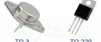
Types of TL431
The TL431 is produced in various housing variations. Depending on the type of installation, you can choose the one that suits your project. For through-hole and surface mounting: TO-92, and for surface mounting: SOT-23, SOT-25, SOT-89 and SOP-8.
For prototyping and simple homemade projects without using printed circuit boards, the TO92 is the most convenient option, since it can be used both in conjunction with a breadboard and with surface mounting.
Description
TL431 – datasheet in Russian. The TL431 is a parallel-type adjustable voltage regulator (integral analogue of a zener diode) and is designed for use as a reference and adjustable zener diode with guaranteed thermal stability over the applicable commercial temperature range.
The output voltage can be set at any level from 2.495 V (VREF) to 36 V, for this two external resistors are used, which act as a voltage divider.
This regulator has a wide operating current range from 1.0 mA to 100 mA with a dynamic resistance of 0.22 ohms. The TL431's active output elements provide sharp turn-on characteristics, making it perform better than conventional zener diodes in many applications.
±0.4% voltage reference accuracy (TL431B) eliminates the need for a variable resistor, saving costs and reducing drift and reliability issues.
Testing TL431 using the M328 Universal Component Tester
Let me make a reservation right away that this article is not a panacea. This may not work for some people.
First, I'll talk about the TL431 and what it does. TL431 is a controlled zener diode with which you can obtain a stabilized voltage within a wide range from 2.5 volts to 36 volts. Using this microcircuit, you can make a reference voltage source for power supplies, as well as for various measuring circuits.
Figure taken from ON Semiconductor datasheet
Below are two datasheet options for this chip.
The pinout of this chip is best displayed in the ON Semiconductor datasheet
One small detail found in the Texas Instruments datasheet
In all the figures there is one inscription “top view”, this translates as “top view”; if you look at the datasheet inattentively, without knowing what this may mean, you can solder it incorrectly on the board.
I used the TL431 chip in one of my circuits, and it turned out to be faulty. After searching the forums, I found a way to test this microcircuit. And in some places I saw how this microcircuit is called using a multimeter, but, alas, this is not the case. I also first tried to check with a multimeter but immediately put this event aside. And I decided to try to check using a universal component tester, which was previously purchased on Aliexpress.
During the check I made a table. First I checked in dual-terminal mode (if the table shows two pins, you just need to combine both pins together).
Source: cxem.net
A simple lithium battery charger.
The main difference between a charger and a power supply is a clear limitation of the charging current. The following circuit has two limiting modes: - current; — by voltage;
As long as the output voltage is less than 4.2 V, the output current is limited; when the voltage reaches 4.2 V, the voltage begins to be limited and the charging current decreases. In the following diagram, current limitation is carried out by transistors VT1, VT2 and resistors R1-R3. Resistor R1 performs the function of a shunt, when the voltage across it exceeds 0.6 V (opening threshold VT1), transistor VT1 opens and closes transistor VT2. Because of this, the voltage at the base of VT3 drops; it begins to close and, consequently, the output voltage decreases, and this leads to a decrease in the output current. This is how current feedback and stabilization works. When the voltage approaches the level of 4.2 V, DA1 begins to come into operation and limit the voltage at the output of the charger.
And now a list of circuit component values:
- DA1 – TL431C;
- R1 – 2.2 Ohm;
- R2 – 470 Ohm;
- R3 – 100 kOhm;
- R4 – 15 kOhm;
- R5 – 22 kOhm;
- R6 – 680 Ohm (needed to adjust the output voltage);
- VT1, VT2 – BC857B;
- VT3 – BCP68-25;
- VT4 – BSS138.
Time relay
The TL431 has found its use not only as a voltage reference source, but also in many other applications. For example, due to the fact that the input current of TL431 is 2-4 μA, a time relay can be built on the basis of this microcircuit: when contact S1 opens, C1 begins to slowly charge through R1, and when the voltage at the input of TL431 reaches 2.5 V, the output transistor DA1 opens and through The LED of the PC817 optocoupler will begin to flow current, and accordingly the phototransistor will open and close the external circuit. In this circuit, resistor R2 limits the current through the optocoupler and stabilizer (for example, 680 Ohms), R3 is needed to prevent the LED from igniting from the TL431’s own current (for example, 2 kOhms).
For car inverters
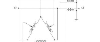
For automotive inverters, AC zener diodes TL431 are often used. The connection circuit in this case involves the use of two-digit triodes. The filters themselves are used in the open type. If we consider circuits without an expander, the threshold voltage fluctuates around 10 W.
The direct operating current is 4 A. The system overload parameter is allowed at 3 mA. If we consider modifications with expanders, then in this case high-capacity modulators are installed. Resistors are used as standard selective type.
In some cases, amplifiers of different power are used. The threshold voltage parameter, as a rule, does not exceed 12 W. The output impedance of the system can range from 70 to 80 ohms. The stabilization accuracy rate is approximately 2%. The operating current of the systems is no more than 4.5 A. The zener diodes are directly connected through the cathode.
Connection schemes
The LM317 stabilizer has proven itself to be a universal microcircuit capable of stabilizing voltage and Amperes. Over decades, hundreds of LM317T switching circuits for various applications have been developed. The main purpose is a voltage stabilizer in power supplies. To increase the number of amperes at the output there are several options:
- connection in parallel;
- installing power transistors at the output, we get up to 20A;
- replacement with powerful analogues LM338 up to 5A or LM350 up to 3A.
To build a bipolar power supply, negative voltage stabilizers LM337 are used.
I think that parallel connection is not the best option due to the difference in the characteristics of the stabilizers. It is impossible to set several pieces to exactly the same parameters in order to distribute the load evenly. Due to the spread, one will always have more load than the others. The probability of failure of a loaded element is higher; if it burns, the load on others, which may not be able to withstand it, will sharply increase.
In order not to connect in parallel, it is better to use transistors at the output for the power part of the DC-DC voltage converter. They are designed for high current and have better heat dissipation due to their large size.
Modern pulse chips are inferior in popularity, but their simplicity is hard to beat. The lm317 current stabilizer for LEDs is easy to set up and calculate, and is currently still used in small-scale production of electronic components.
LED driver LED driver up to 5A
Battery charger
Adjustable bipolar power supply from 0 to 36V
Bipolar power supply LM317 and LM337, for obtaining positive and negative voltage.
How to check TL431?
Date: 09.25.2015 //
The TL431 chip is a controlled zener diode. It is often found in PC power supplies, etc. If it fails, it can lead to a lot of troubles, such as glitches in the operation of the motherboard and similar phenomena. If there is a suspicion that this component is faulty, it is better to replace it immediately. But if there is nothing at hand to replace, and a performance check is necessary, how to check the TL431 in this case? For this procedure, I hope you find our article useful.
Low voltage indicator
The difference between this circuit and the previous one is that the LED is connected differently. This connection is called inverse, since the LED lights up only when the TL431 chip is locked.
If the monitored voltage value exceeds the level determined by the divider Rl and R2, the TL431 chip opens and current flows through resistance R3 and pins 3-2 of the TL431 chip. At this moment, there is a voltage drop on the microcircuit of about 2V, and it is clearly not enough to light the LED. To completely prevent the LED from burning, 2 diodes are additionally included in its circuit.
At the moment when the value under study is less than the threshold determined by the divider Rl and R2, the TL431 microcircuit will close, and the potential at its output will be significantly higher than 2V, as a result of which the HL1 LED will light up.
Tester electrical circuit
There are many schemes for such verification in the virtual space of the Internet. The difference between them is that some report - signal the serviceability of the electronic component by blinking - lighting up the LEDs, others create the prerequisites for measuring the voltage at the output, the value of which should be used to judge the serviceability of the TL431. On the one hand, the former seem to be self-sufficient, but in addition to the latter, a voltmeter is needed. On the other hand, the former need to “take their word for it,” while the latter “do not decide anything” themselves, but provide objective information for making a decision. In addition, a voltmeter is always at hand. I chose the second option, it is also simpler, the “price of the issue” is three constant resistors.
Finding a suitable housing to fit everything you need into it is not a problem; the website has an article “Making a power plug with a non-standard housing.” I started with equipping the top cover of the case; for this I needed a three-pin socket, a push button and a notebook sheet in a box on which a circle was drawn in accordance with the diameter of the cover and an awl to mark the installation locations of the socket and button. The cut out circle had already become a template, was placed on the lid and the corresponding markings were made on it with an awl. Next, using the same awl, holes of the required diameter were pierced for the contacts of the socket and button.
So, a socket and a button are installed on the top cover (their contacts are bent from the inside and soldered with tin), a “tulip” is installed on the middle part of the case as a power connector, and pins for connecting to a multimeter are located on the bottom cover. The fact that some parts (two lids and a neck) of a plastic container (milk bottle) acted as a body is probably clear and without explanation.
All that remains is to mount the circuit itself on the inside of the cover, on the contacts of the socket and the button; first of all, three resistors were installed, and all the connecting wires were soldered into the second. There were unexpectedly a lot of wires, there is no need to rush here - it’s not surprising to get confused.
This time I did not use glue for additional fastening, but “planted” everything on small screws. Three pieces on each element. This way it’s more maintainable, although it’s unlikely that anything will need to be repaired here. The sample is collected, once and for all. It remains to check its operation and, accordingly, the serviceability of the available reference voltage sources TL431.
Since the matter has “burnt out” and there is now a probe, all that remains is to remember this and be able, if necessary, to quickly identify it from among others in the same cases that are in the box intended for this. You also need to remember that the operating voltage of the probe is 12 volts, that when the TL431 is not connected, the multimeter will show a voltage of 10 volts, when it is connected 5 volts, and when the button is pressed 2.5 volts, and in addition, correctly install the component being tested in the socket. Or you don’t have to remember much, but design the front panel accordingly. Author of the project: Babay iz Barnaula .
Discuss the article CHECKING THE TL431 REFERENCE VOLTAGE SOURCE
Source: radioskot.ru
AC models
Cherry AC zener diodes TL431 are often used for dipole inverters. How to check the functionality of the connected element? This can be done using a regular tester. The output resistance parameter must be no more than 70 Ohms
It is also important to note that devices in this series are switched on via a vector converter
In this case, scalar modifications are not suitable. This is largely due to the low threshold of current conduction
It is also important to note that the nominal voltage does not exceed 4 W. The operating current in the circuit is maintained at 2 A
To reduce heat losses, various thyristors are used. Today, expansion and phase modifications are produced.
Stabilizer check
A pertinent question immediately arises about how to check the tl431 with a multimeter . As practice shows, you won’t be able to check with just a multimeter. To test the tl431 with a multimeter, you should assemble a circuit. To do this you will need: three resistors (one of them is trimmer), an LED or light bulb, and a 5V DC source.
Resistor R3 must be selected in such a way that it limits the current to 20 mA in the power circuit. Its nominal value is approximately 100 ohms. Resistors R2 and R3 act as a balancer. As soon as the voltage is 2.5 V at the control electrode, the LED junction will open and the voltage will flow through it. This circuit is good because the LED acts as an indicator.
The DC source - 5V is fixed, and the tl431 microcircuit can be controlled using a variable resistor R2. When power is not supplied to the microcircuit, the diode does not light up. After the resistance is changed using a trimmer, the LED lights up. After this, the multimeter must be switched to DC measurement mode and measure the voltage at the control terminal, which should be 2.5. If voltage is present and the LED is on, then the element can be considered working.
Characteristics
The maximum permissible characteristics of the KR142EN5A strongly depend on the temperature of its case (TCORP) and are listed in the manufacturers’ datasheet separately from the rest. Let's list them:
maximum input voltage (UВХ.) up to 15 V, at TKORP. = — 45 …+ 70 °C;
at TKORP. = — 45 …+ 100 °C:
- output voltage (UOUT) is in the range 4.9 ... 5.1 V;
- power dissipation (РMAX) without a radiator no more than 1.5 W, with a heat sink up to 10 W;
- limit output current (at P ≤ PMAX.) IMAX. up to 1.5 A.
Electrical parameters
In addition to the maximum permissible values, KR142EN5A has electrical parameters. They are given together with additional conditions for their measurement. All values in this list are valid only under the condition of the ambient temperature TOKR. = + 25OS.
Analogs
The KR142EN5A linear voltage regulator is an analogue of the first-generation foreign microcircuits of the LM7805 series, first introduced in the 70s by the American company Fairchild Semiconductor. This is a popular imported IC from the 78xx series, as it has the most common +5 V output for powering various devices. Modern analogues of the microcircuit are: A7805T, KIA7805, L7805CV, LM7805. The domestic KR142EN5V can also be considered as a full replacement.
Marking features
Not all copies of KR142EN5A have full markings on the body. Instead, a conditional code is indicated, by which the “crank” is recognized. In this case, the following information is applied to the case: manufacturer's brand, type of microcircuit, year and week of manufacture.
There is also another abbreviated designation for this device - KREN 5A.
TL431, what kind of “beast” is this?
Nikolay Petrushov
Rice. 1
TL431.
TL431 was created in the late 70s and is still widely used in industry and in amateur radio activities. But despite its advanced age, not all radio amateurs are closely familiar with this wonderful case and its capabilities. In this article I will try to familiarize radio amateurs with this microcircuit. First, let’s look at what’s inside it and turn to the documentation for the microcircuit, the “datasheet” (by the way, analogues of this microcircuit are KA431, and our KR142EN19A, K1156ER5x microcircuits). And inside it there are about a dozen transistors and only three outputs, so what is it?
Rice. 2
Device TL431.
It turns out everything is very simple. Inside is a conventional op-amp (triangle in the block diagram) with an output transistor and a reference voltage source. Only here this circuit plays a slightly different role, namely the role of a zener diode. It is also called “Controlled Zener diode”. How does he work? Let's look at the TL431 block diagram in Figure 2. From the diagram you can see that the op-amp has a (very stable) built-in 2.5 volt reference voltage source (small square) connected to the inverse input, one direct input (R), a transistor at the op-amp output, a collector ( K) and an emitter (A), which are combined with the power supply terminals of the amplifier and a protective diode against polarity reversal. The maximum load current of this transistor is up to 100 mA, the maximum voltage is up to 36 volts.
Rice. 3
Pinout TL431.
Now, using the example of a simple circuit shown in Figure 4, let’s look at how it all works. We already know that inside the chip there is a built-in reference voltage source - 2.5 volts. In the first releases of microcircuits, which were called TL430, the voltage of the built-in source was 3 volts; in later releases, it reaches 1.5 volts. This means that in order for the output transistor to open, it is necessary to apply a voltage slightly higher than the reference 2.5 volts to the input (R) of the operational amplifier (the prefix “slightly” can be omitted, since the difference is several millivolts and in the future we will assume that a voltage equal to the reference must be applied to the input), then a voltage will appear at the output of the operational amplifier and the output transistor will open. To put it simply, TL431 is something like a field-effect transistor (or just a transistor), which opens when a voltage of 2.5 volts (or more) is applied to its input. The opening-closing threshold of the output transistor is very stable here due to the presence of a built-in stable reference voltage source.
Rice. 4
Circuit diagram for TL431.
From the diagram (Fig. 4) it can be seen that a voltage divider consisting of resistors R2 and R3 is connected to the R input of the TL431 microcircuit, resistor R1 limits the LED current. Since the divider resistors are the same (the power supply voltage is divided in half), the output transistor of the amplifier (TL-ki) will open when the power source voltage is 5 volts or more (5/2 = 2.5). In this case, 2.5 volts will be supplied to the R input from the divider R2-R3. That is, our LED will light up (the output transistor will open) when the power source voltage is 5 volts or more. It will go out accordingly when the source voltage is less than 5 volts. If you increase the resistance of resistor R3 in the divider arm, then it will be necessary to increase the voltage of the power supply to more than 5 volts, so that the voltage at the input R of the microcircuit supplied from the divider R2-R3 again reaches 2.5 volts and the output transistor TL opens -ki. It turns out that if this voltage divider (R2-R3) is connected to the output of the power supply, and the cathode of the TL-ki to the base or gate of the control transistor of the power supply, then by changing the arms of the divider, for example by changing the value of R3, it will be possible to change the output voltage of this power supply, because at the same time, the TL stabilization voltage (opening voltage of the output transistor) will also change - that is, we will get a controlled zener diode. Or if you select a divider without changing it in the future, you can make the output voltage of the power supply strictly fixed at a certain value. Conclusion; - if the microcircuit is used as a zener diode (its main purpose), then by selecting the resistances of the divider R2-R3 we can make a zener diode with any stabilization voltage within the range of 2.5 - 36 volts (maximum limitation according to the “datasheet”). A stabilization voltage of 2.5 volts is obtained without a divider, if the input of the TL is connected to its cathode, that is, pins 1 and 3 are short-circuited. Then more questions arise. Is it possible, for example, to replace the TL431 with a regular op-amp? — It’s possible only if you want to design it, but you will need to assemble your own 2.5-volt reference voltage source and supply power to the op-amp separately from the output transistor, since its current consumption can open the actuator. In this case, you can make the reference voltage whatever you want (not necessarily 2.5 volts), then you will have to recalculate the resistance of the divider used in conjunction with the TL431, so that at a given output voltage of the power supply, the voltage supplied to the input of the microcircuit is equal to the reference. One more question - is it possible to use the TL431 as a regular comparator and build on it, say, a thermostat, or something similar? — It’s possible, but since it differs from a conventional comparator by the presence of a built-in reference voltage source, the circuit will be much simpler. For example this;
Rice. 5
Thermostat on TL431.
Here the thermistor (thermistor) is a temperature sensor, and it decreases its resistance as the temperature increases, i.e. has a negative TCR (Temperature Coefficient of Resistance). Thermistors with positive TCS, i.e. whose resistance increases with increasing temperature are called posistors. In this thermostat, when the temperature exceeds a set level (regulated by a variable resistor), a relay or some actuator will operate and switch off the load (heating elements) with its contacts, or, for example, turn on the fans depending on the task. This circuit has a small hysteresis, and to increase it, it is necessary to introduce an OOS between pins 1-3, for example, a trimming resistor of 1.0 - 0.5 mOhm and its value must be selected experimentally depending on the required hysteresis. If it is necessary for the actuator to operate when the temperature drops, then the sensor and regulators must be swapped, that is, the thermistor must be included in the upper arm, and a variable resistance with a resistor must be switched on in the lower arm. And in conclusion, you can easily understand how the TL431 microcircuit works in the circuit of a powerful power supply for a transceiver, which is shown in Figure 6, and what role resistors R8 and R9 play here, and how they are selected.
Rice. 6
Powerful 13 volt, 22 amp power supply.
Basic configuration
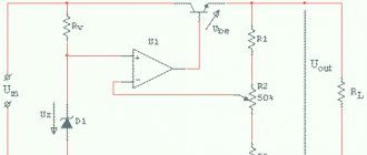
The main task of the stabilizer is to ensure constant output voltage and suppress ripple. The design of the stabilizer is based on the simplest circuit, but I chose each of its elements so that it ideally fulfills its function: To maximize input noise suppression, the resistance of the resistor R should be maximum, and the internal resistance of the reference voltage source Vref should be as low as possible. And the reference voltage driver will work better if it is powered from a high-resistance source. A stable current source (GST) meets these requirements.
For the high-voltage stabilizer, I used a GST with two transistors, which provides greater current stability when the supply voltage fluctuates.
For low-voltage stabilizers, you can use a similar circuit or just a single diode.
For high-voltage stabilizers, I chose a GST current value of about 5mA. For low-voltage stabilizers, you can choose a lower value.
The TL431 chip requires a minimum of 2 mA for normal operation.
Important note: The two-transistor GST can sometimes be excited if high-frequency transistors are used. Therefore, I chose MJ340/350 transistors which, as my experience shows, work stably
Zener diodes are quite noisy and also have a poor temperature coefficient. The output voltage when using them will vary depending on the ambient temperature, and even more so if your amplifier has active ventilation. In addition, the stability of their internal resistance also leaves much to be desired.
I used a TL431 as a voltage reference instead, as their noise performance is quite decent, they have low output impedance and a fairly wide output voltage range that can be set using a simple divider.
Pinout TL431
Transistor voltage stabilizer
For the tl431 integrated circuit, the datasheet is a graphic image that conventionally resembles the part and the pinout of the pins, indicating their number and name. Depending on the design, you should consider the pinout that is suitable for a particular model. For example, a tl431 chip may have letter indices after the numbers: tl431a, tl431c, tl431ac. Typically, the sixth letter in the marking determines the accuracy of the IC:
- 2% – no letter;
- 1% – letter A;
- 0.5% – letter B.
Datasheet tl431 depending on model and design
Manufacturers
Due to its good parameters, reliability and low cost, TL431 is used in various technical solutions. Therefore, many foreign companies are engaged in its production. There is even a fully translated datasheet tl431 in Russian from Texas Instruments (TI). Here are links to some datasheets of devices sold in the Russian Federation: TI, ON Semiconductor, STMicroelectronics, Nexperia, HTC Korea, NXP Semiconductors. There are still manufacturers of these products, but they are difficult to find in Russian stores. These include: Unisonic Technologies, Motorola, Fairchild Semiconductor, Diodes Incorporated, HIKE Electronics, Calogic, Sangdest Microelectronic (Nanjing), SeCoS Halbleitertechnologie GmbH, Hotchip Technology, Foshan Blue Rocket Electronics, etc.
Description of work
The operation of the lm324n microcircuit is based on the simultaneous functioning of four op-amps inside it. All amplifiers are powered from the same power source, have inverting and non-inverting inputs and the same output. The power source can be unipolar or bipolar.
Let's look at the internal circuit of one of the single-supply operational amplifiers. Let's take it directly from the datasheet for LM324.
Functionally, each operational amplifier consists of: a differential stage, as well as intermediate and output amplification stages.
The differential cascade performs the functions of amplifying the difference between the voltages supplied to the input (V+ and V—) and neutralizing common-mode signals. Provides high input resistance.
The intermediate stage provides balancing of the opamp (setting the output to zero voltage when the inputs are closed), matching the resistances of the differential and output stages, as well as frequency correction (protection against self-excitation).
The output stage provides low output impedance, load power requirement, current limiting and short circuit protection.
Marking
The LM series is based on integrated circuits manufactured by National Semiconductor. The prefix LM originally meant linear monolithic (linear, monolithic) and was used to designate general purpose amplifiers (General Purpose) for which there were no strict requirements. The numbers “324” indicate the serial number of the chip. The "-N" at the end of the serial number denotes devices purchased by Texas Instruments from National Semiconductor. In September 2011, National Semiconductor was taken over by Texas Instruments, which did not change the LM prefix on its products. Therefore, currently the LM marking is the Texas Instruments manufacturer code, but it is widely used by other manufacturers when releasing their analogues of this chip.
It should also be noted that manufacturing companies are constantly improving their products. Currently, modifications that are superior in a number of functions have appeared, for example: LM324K, LM324KA with internal protection against electrical discharge (HBM ESD); micropower LP324 with current consumption of 21 μA; low-voltage LMV324, with supply voltage from 2.7 V to 5.5 V; LPV324, manufactured using BiCMOS technology and a current consumption of 9 µA, etc. Amplifiers with the symbol “A” in the marking, for example “LM324A-N”, will have better VIO characteristics compared to others (without “A”).
Diagram for 15 V blocks
The zener diode TL431 switching circuit through a 15 V block is carried out using a single-stage converter. In turn, the modulator is suitable with a capacitance of 5 pF. Resistors are used exclusively of the selective type. If we consider modifications with triggers, then the threshold voltage parameter does not exceed 3 W. The stabilization accuracy is around 3%. Filters for the system are suitable for both open and closed types.
It is also important to note that an expander may be installed in the circuit. Today, models are produced mainly of the switched type
For modifications with transceivers, the current conductivity does not exceed 4 microns. In this case, the sensitivity of the zener diode fluctuates around 30 mV. The output impedance reaches approximately 80 Ohms.
Current stabilizer on tl431
Based on the operational current amplifier tl431, you can create a simple stabilizer. To create the required U value, three resistors will be needed. It is necessary to calculate the nominal value of the programmed voltage of the stabilizer. The calculation can be made using the formula: Uout=Vref( 1 + R1/R2 ). According to the formula, U at the output depends on the values of R1 and R2. The higher the resistance of R1 and R2, the lower the output stage voltage. Having received the rating of R2, the value of R1 can be calculated as follows: R1=R2(Uout/Vref – 1). The adjustable stabilizer can be activated in three ways.
It is necessary to take into account an important nuance: the resistance R3 can be calculated using the formula by which the ratings of R2 and R2 were calculated. You should not install a polar or non-polar electrolyte in the output stage to avoid interference at the output.
Specifications
In power supplies from a 220V network, a linear stabilizer is usually installed immediately after the rectifier diode bridge, where it performs its main role as a secondary power supply source (PSPS). The input voltage recommended by manufacturers for KREN8B is in the range of 14.5 ... 18 V. In any case, it should be 2.5-3 V more than the reference one.
Maximum parameters
Manufacturers declared the following maximum parameters for KR142EN8B, at case temperature (TC) from -45 to +70°C, unless otherwise specified:
- input voltage (at TC from -45 to +100°C) - up to 30 V;
- dissipation power – up to 1.5 W; up to 8 W (with heat sink);
- load current – up to 1500 mA (using a heat sink).
Electrical parameters
If the load current is more than 100 mA, then the use of a heat sink is recommended. In practice, its value can reach 900 mA, which is much less than the value stated by individual manufacturers in the datasheet, but quite sufficient for most modern low-current systems. Information about the electrical parameters of KREN8B, at an ambient temperature of +25 ° C, is presented in the table below.
Typical connection
The stable operation of electronic devices is ensured by the stability of the power supply supplied to them. Hence the need to level it to the required level arises. Exceeding or decreasing the supply values is unacceptable, as it leads to malfunction of the equipment. The most obvious way is to use a popular domestic microcircuit from the KR142 series.
KR142EN8B is one of the linear stabilizers of this series. Its typical connection diagram is very simple and is suitable for all KR142EN. It includes the Krenka itself (another unofficial name 142EN8B) and a pair of smoothing capacitors. The datasheet recommends the use of small capacitors with values of 0.33 and 1.0 µF. Ceramic or tantalum versions are usually used.
If aluminum electrolytic capacitors are selected for the project, they must be at least 10 µF. It is better to connect them as close as possible to the pins of the microcircuit. Many radio amateurs do this by mounted installation, soldering the legs of the radio elements together.
Independent chip-based devices
This chip is used in power supplies for televisions and computers. However, on its basis it is possible to create independent electrical circuits, some of which are:
- current stabilizer;
- sound indicator.
Current stabilizer
The current stabilizer is one of the simplest circuits that can be implemented on the tl 341 microcircuit. It consists of the following elements:
- power supply;
- resistance R 1, connected via a common point to the + power line;
- shunt resistance R 2 k - power line;
- a transistor whose emitter is connected to the - line through resistor R2, the collector to the output - line, and the base through a common point to the cathode of the microcircuit;
- tl 341 microcircuit, whose anode is connected to the - line using a common current, and the ref pin is connected to the emitter circuit of the transistor also using a common point.
Sound indicator
The sound indicator based on tl 341 is a simple circuit shown in Figure 5.
Such a sound indicator can be used to monitor the water level in a container. The sensor is an electronic circuit in a housing with two output electrodes made of stainless steel, one of which is located 20 mm higher than the other.
At the moment the sensor leads come into contact with water, the resistance decreases and tl 341 transitions to linear mode through resistors R 1 and R 2. This contributes to the appearance of auto-generation at the resonant frequency and the formation of an audio signal.
What can be replaced
Today you can replace the device with a domestic or foreign analogue. TL431, TL431A, TL431ACD, TL431ACZ, TL431CLP, TL431CD and others do an excellent job.
The main analogue of the TL 431 pinout is TL431CD
In general, the TL431 pinout is an adjustable zener diode used as a voltage reference in various power supplies. From the very beginning of its release, it was used in computers, laptops and other electronics. The principle of its operation is simple: the operational amplifier opens the transistor and current begins to flow to the anode. It has its own relay, current stabilizer and charger. Analogue equipment is TL431CLP, TL431CD and others.
Analogs TL431
IC tl431 analogue, which needs to be selected, belongs to the control zener diodes. Therefore, it is necessary to select a similar IC based on electrical parameters: reference voltage, input voltage, operating current and design features.
Carefully. Analogues can be: complete, closest and functional. Depending on the new part, additions and changes to the electronic circuit where it will be installed (replaced) are possible. When selecting an analogue, you should take into account that the first two letters before the numbers are the name of the manufacturer.
For example, the transistor az431, the characteristics of which, when tested, coincide with tl431, is the same, it’s just a different manufacturer.
Some analogues for TL431