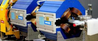
Nikola Tesla, like many other physicists, devoted many years of his life to studying the energy of currents and methods of its transmission, creating unique developments. One of them was a Tesla coil - a resonant transformer designed to produce high-frequency currents.
Tesla was definitely a genius. It was he who brought the use of alternating current to the world and patented many inventions. One of them is the famous Tesla coil, or transformer. If you have certain knowledge and skills, you can easily create a Tesla coil at home. Let's find out what the essence of this device is and how to create it at home if you suddenly really want it.
What is a Tesla coil and why is it needed?
As noted earlier, a Tesla coil is a resonant transformer. The purpose of a transformer is to change the voltage value of an electric current. These devices are respectively lowering and increasing.
Read more about transformers, their general structure and purpose in our separate material.
From an electronics point of view, a Tesla coil consists of two windings without a common core and with a different number of turns. Tesla transformer is a step-up transformer. The voltage at the output of such a transformer increases hundreds of times and can reach values of the order of a million volts.
Tesla's invention not only works, but works very spectacularly. By turning on the transformer, you can observe spectacular discharges (lightning), the length of which reaches several meters.
Application area
It is incorrect to assume that the Tesla transformer does not have wide practical applications. It is used to ignite gas discharge lamps and to detect leaks in vacuum systems. However, its main use today is cognitive and aesthetic. The table below shows the effects that occur during operation of a Tesla transformer.
Effects that occur during operation of a Tesla transformer.
This is mainly due to significant difficulties when it is necessary to control the selection of high-voltage power, or even more so, transfer it to a distance from the transformer, since in this case the device inevitably goes out of resonance, and the quality factor of the secondary circuit is also significantly reduced.
What does a Tesla coil consist of?
Before assembling the Tesla coil, let's look at its components and shape.
Toroidal figures: what are they?
The Tesla coil is made in the shape of a Torus (toroidal figure, toroid).
Toroidal figures are primarily a concept from geometry. A torus is a surface obtained by rotating a generatrix of a circle around an axis lying in the plane of this circle.
It's better to look once than to try to imagine. The figure below shows toroidal surfaces.
The toroid is an important component of the Tesla coil and is usually made of aluminum corrugation. As part of this device, it performs the following functions:
- reduces the resonant frequency;
- accumulates energy before streamer formation;
- creates an electrostatic field that repels the streamer from the secondary winding of the transformer.
By the way, you can read about what a streamer is in our separate article on lightning.
You can't help but notice the funny play on words. In Norse mythology, Thor is the god of thunder and lightning. The component of a Tesla coil, due to which a discharge (lightning) is formed, is a torus, or toroid.
Secondary winding
The secondary winding is the main component of the Tesla coil, which is also simply called the “secondary”. The winding, as a rule, contains about 800-1200 turns, and it is wound on PVC pipes, which can be bought at a regular hardware store.
Based on the required number of turns, the diameter of the winding wire is selected. The standard ratio of the length of the secondary winding of the coil to its diameter is 4:1 or 5:1. To prevent the coils from spreading, they are coated with varnish.
Primary winding and protective ring
The primary winding (or primary) of a Tesla coil must have low resistance because it will carry a lot of current. It is usually made from wires with a cross-section of more than 6 millimeters. Also, copper pipe for air conditioners is often used as the primary winding.
The shape of the primary winding is cylindrical, flat or conical.
The protective ring is an open flat turn of grounded copper wire. The ring is installed so that the toroid streamer, once in the primary winding, does not damage the electronics.
Self-assembly diagram
This scheme has a minimum of elements, which does not make our task any easier. After all, for it to work, it is necessary not only to assemble it, but also to configure it. Let's start with ILOs.
There is such a transformer in the microwave. It is a regular power transformer with the only difference that its core operates in a mode close to saturation.
Assembly diagram of a homemade Tesla transformer.
This means that despite its small size, it has a power of up to 1.5 kW. However, there are also negative aspects to this mode of operation. This includes a high idle current, about 2-4 A, and strong heating even without a load; I am silent about heating with a load. The usual output voltage of the MOT is 2000-2200 volts with a current of 500-850 mA.
MOT for Tesla transformer.
For all MOTs, the “primary” is wound at the bottom, the “secondary” at the top. This is done to ensure good insulation of the windings.
On the “secondary”, and sometimes on the “primary”, the filament winding of the magnetron is wound, about 3.6 volts.
Moreover, between the windings you can see two metal jumpers. These are magnetic shunts.
Their main purpose is to close on themselves part of the magnetic flux created by the “primary”.
Thus, limit the magnetic flux through the “secondary” and its output current at a certain level.
Attention! We ask amateurs to refuse this work! Dangerous, high voltage, lethal! Although the voltage is small compared to the lineman, the current strength, a hundred times greater than the safe limit of 10 mA, will reduce the chances of staying alive to almost zero.
KAPs mean high-voltage ceramic capacitors (series K15U1, K15U2, TGK, KTK, K15-11, K15-14 - for high-frequency installations!).
HF filter for homemade Tesla.
HF filter: respectively, two coils that perform the function of filters from high frequency voltage.
Each contains 140 turns of varnished copper wire 0.5 mm in diameter.
A spark plug, which is needed for switching power and exciting oscillations in the circuit.
If there is no spark switch in the circuit, then there will be power, but there will be no oscillations. And the power supply begins to siphon through the primary - and this is a short circuit!
Spark plug for a homemade Tesla transformer.
As long as the spark switch is not closed, the caps are charging. As soon as it closes, oscillations begin. Therefore, they install ballast in the form of throttles - when the spark plug is closed, the throttle prevents the flow of current from the power supply, it charges itself, and then, when the spark gap opens, it charges the caps with redoubled anger.
Finally, the turn has come to the Tesla transformer itself: the primary winding consists of 7-9 turns of wire of a very large cross-section.
However, a plumbing copper pipe will do. The secondary winding contains from 400 to 800 turns, here you need to adjust.
Do-it-yourself finished Tesla transformer coil.
Power is supplied to the primary winding. The secondary has one terminal reliably grounded, the second is connected to the TORU (lightning emitter).
The torus can be made from ventilation corrugation. That's all. Remember to be safe and good luck with your DIY build.
The concept of ether and Tesla's ideas
Now we know what a Tesla coil consists of. But what is the history of this invention? To answer this question, it is worth understanding what ether is.
Ether is a physical medium, a hypothetical substance or field that fills the space of the Universe. The ether is responsible for the propagation of electromagnetic and gravitational interactions.
At the moment, the theory of the ether is not used in modern physics, since after the advent of the theory of relativity, the need for the concept of “ether” simply disappeared.
However, new views on the concept of ether are emerging, and it should not be completely written off. Many scientists are still debating whether ether exists or not, and a new section has even appeared in physics that studies this issue (ether dynamics).
Nikola Tesla proved the existence of ether with his experiments. The scientist had an idea to use ether as a source of energy. Thus, Tesla wanted to abandon wired transmission of energy and transmit electricity throughout the world wirelessly through the ether. To do this, it was planned to install two giant coils at the Earth's poles.
Unfortunately, the direction Tesla chose was not developed at a deeper level. In addition, he was considered a strange scientist who never wanted to take the path of seeking the economic benefits of his research. In addition, another era was coming - the time of vacuum inventions.
Many of Tesla's archives were lost under mysterious circumstances. Even if Tesla found out how to obtain a practically inexhaustible source of energy, this information is not available now. The rare genius of Tesla was ahead of his time, and the world was simply not ready for his ideas.
Description of the device
In short, a Tesla coil (CT) is a resonant transformer that creates a high-frequency current. There is information that in their experiments, the military brought the coil to a power of 1 THz.
Huge Tesla Coil
Here it is worth raising the following question: why did Tesla invent it? According to the records, the scientist was working on technology for wireless transmission of electricity. The question is extremely relevant for all humanity. In theory, with the help of ether, two powerful CTs located a couple of kilometers from each other will be able to transmit electricity. To do this, they must be tuned to the same frequency. There is also an opinion that CT can become a kind of perpetual motion machine.
The introduction of this technology will make all the nuclear power plants, thermal power plants, hydroelectric power stations and others available today simply unnecessary. Humanity will not have to burn solid fossils, be at risk of radiation contamination, or block river beds. But the answer to the question of why no one is developing this technology remains with conspiracy theorists.
Tabletop Tesla coil, sold today as a souvenir
Tesla Coil Configurations
The Tesla transformer has many modifications, depending on this it is used in different areas of life:
- A coil with a rotary mechanism with sparks rotating in different positions. Here, the role of the engine is played by an electric unit with a rotating disk that conducts electrodes.
- Lamp coil with conventional lamps to generate high voltage current. They are capable of conducting voltages up to 600 Volts.
- Semiconductor oscillator with high-frequency master oscillator (more modern design).
- High frequency transformer that outputs current through musical waves. The discharge changes depending on the musical rhythm.
It is enough to change the discharge key to change its type and thereby achieve different discharge forms.
The main difference between them all is their fairly quiet operation, since the spark itself makes little noise.
Generator application
The Tesla generator and transformer were designed by the inventor as universal devices for wireless transmission of electrical energy. Nikola Tesla repeatedly conducted experiments confirming his theory, but, unfortunately, traces of the energy transfer reports were also lost or safely hidden, like many of his other designs. Developers have only recently begun to design devices to transmit energy, but only over relatively short distances (wireless phone chargers are a good example).
In an era of inevitable depletion of non-renewable natural resources (hydrocarbon fuels), the development and construction of alternative energy devices, including a fuel-free generator, is of great importance. A free energy generator with sufficient power can be used for lighting and heating homes. You should not refuse research citing a lack of experience and specialized education. Many important inventions were made by people who were professionals in completely different fields.
What is unique about the Tesla Coil?
The main difference of this invention is that its inventor was able to obtain a voltage exceeding 15 million volts at a frequency of several hundred kilohertz. This device looks incredibly strange, scary, but also beautiful at the same time: the absence of an iron core, a thick outer layer of the primary winding and a thick inner layer of the secondary winding. But there are also disadvantages. For example, making a large turn while ensuring excellent thermal contact with the transformer core is quite difficult.
By the way, if you suddenly need to write any paper on physics, we have tasty discounts
Many are trying to repeat the numerous unique experiments of the great genius. However, to do this, they will have to solve the most important problem - how to make a Tesla coil at home. But how to do that? Let's try to describe it in detail so that you can do it the first time.
Security measures
Once you have collected the CT, you need to take some precautions before launching. First, you need to check the wiring in the room where you plan to connect the transformer. Secondly, check the insulation of the windings.
You might be interested in Electrical tester
It is also worth remembering the simplest precautions. The voltage of the secondary winding is on average 700A, 15A is already fatal for a person. Additionally, it is worth putting away all electrical appliances; if they get into the coil’s operating area, they are likely to burn out.
CT is a revolutionary discovery of its time, underestimated today. Today the Tesla transformer is used only for the entertainment of home electricians and in light shows. You can make a coil yourself using available materials. You will need a PVC pipe, several hundred meters of copper wire, a couple of meters of copper pipes, a transistor and a couple of resistors.
How to make a Tesla coil at home with your own hands
On the Internet you can find a lot of information on how to make a musical or mini Tesla coil with your own hands. But we will tell you and clearly show with illustrations how to make a simple 220 Volt Tesla coil at home.
Since this invention was created by Nikola Tesla for experiments with high-voltage charges, it contains the following elements: a power source, a capacitor, 2 coils (the charge will circulate between them), 2 electrodes (the charge will slip between them).
The Tesla coil is used in a variety of devices: from television and particle accelerators to toys for children.
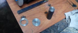
To get started you will need the following parts:
- power supply from neon signs (supply transformer);
- several ceramic capacitors;
- metal bolts;
- hair dryer (if you don’t have a hair dryer, you can use a fan);
- varnished copper wire;
- metal ball or ring;
- toroidal shapes for coils (can be replaced with cylindrical ones);
- safety bar;
- chokes;
- ground pin.
Creation should occur in the following stages.
Design
First, you need to decide what size the coil should be and where it will be located.
If finances allow, you can create a huge generator at home. But you should remember one important detail : the coil creates many spark discharges that greatly heat the air, causing it to expand. The result is thunder. As a result, the created electromagnetic field is able to disable all electrical appliances. Therefore, it is better to create it not in an apartment, but somewhere in a more secluded and remote corner (garage, workshop, etc.).
If you want to determine in advance how long the arc your coil will produce or the power of the required power supply, make the following measurements: divide the distance between the electrodes in centimeters by 4.25, square the resulting number. The final number will be your power in Watts. And vice versa - to find out the distance between the electrodes, the square root of the power must be multiplied by 4.25. A Tesla coil that will be able to create an arc one and a half meters long will require 1,246 watts. And a device with a one-kilowatt power supply can make a spark 1.37 meters long.
Next we study the terminology. To create such an unusual device, you will need to understand highly specialized scientific terms and units of measurement. And in order not to make a mistake and do everything correctly, you will have to learn to understand their meaning and significance. Here is some information that will help:
- What is electrical capacitance ? This is the ability to accumulate and hold an electrical charge of a certain voltage. Something that stores electrical charge is called a capacitor. Farad is a unit of measurement of electrical charges (F). It can be expressed as 1 ampere second (Coulomb) multiplied by a volt. Typically, capacitance is measured in millionths and trillionths of farads (micro- and picofarads).
- What is self-induction? This is the name for the phenomenon of the occurrence of EMF in a conductor when the current passing through it changes. High-voltage wires carrying low-ampere current have high self-inductance. Its unit of measurement is henry (H), which corresponds to a circuit in which changing current at a rate of one ampere per second creates an emf of 1 Volt. Typically, inductance is measured in milli- and microhenry (parts per thousand and parts per million).
- What is resonant frequency ? This is the name of the frequency at which losses in energy transmission will be minimal. In a Tesla coil, this will be the frequency of minimum losses when transmitting energy between the primary and secondary windings. Its unit of measurement is hertz (Hz), that is, one cycle per second. Typically, resonant frequency is measured in thousands of Hertz or kilohertz (kHz).
Gathering the necessary parts
We have already written above what components you will need to create a Tesla coil at home. And if you are a radio amateur, you will certainly have some (or even all) of these.
Here are some features of the necessary parts:
- the power source must supply, through an inductor, a storage or primary oscillating circuit consisting of a primary coil, a primary capacitor and a spark gap;
- the primary coil should be located near the secondary coil, which is an element of the secondary oscillating circuit, but the circuits should not be connected by wires. As soon as the secondary capacitor accumulates a sufficient charge, it will immediately begin to release electrical charges into the air.
Making a Tesla Coil
- Selecting a transformer . It is the supply transformer that will decide what size your coil will be. Most of these coils are powered by transformers capable of delivering current from 30 to 100 milliamps at a voltage of five to fifteen thousand volts. You can find the required transformer at the nearest radio market, on the Internet, or remove it from a neon sign.
- Making a primary capacitor . It can be assembled from several smaller capacitors, connecting them in a circuit. Then they will be able to accumulate equal shares of charge in the primary circuit. True, it is necessary that all small capacitors have the same capacity. Each of these small capacitors will be called composite.
You can purchase a small capacitor on the radio market, on the Internet, or remove ceramic capacitors from an old TV. However, if you have golden hands, you can make them yourself from aluminum foil using plastic film.
To achieve maximum power, the primary capacitor must be fully charged every half power cycle. For a 60 Hz power source, charging needs to occur 120 times per second.
- We are designing a spark gap . To make a single arrester, use a minimum of six millimeter (thick) wire. Then the electrodes will be able to withstand the heat that is generated during charging. In addition, it is possible to make a multi-electrode or rotary spark gap, and also to cool the electrodes by air blowing. An old household vacuum cleaner is perfect for these purposes.
- We make the winding of the primary coil . We make the coil itself from wire, but you will need a form around which you will have to wind the wire. For these purposes, varnished copper wire is used, which can be bought at an electronics store or simply removed from any old unnecessary electrical appliance. The shape around which we will wind the wire should be conical or cylindrical (plastic or cardboard tube, old lampshade, etc.). Due to the length of the wire, the inductance of the primary coil can be adjusted. The latter should have low inductance, so it should have a small number of turns. The wire for the primary coil does not have to be solid - several can be fastened together to adjust the inductance during assembly.
- We assemble the primary capacitor, spark gap and primary coil into one circuit . This circuit will form the primary oscillatory circuit.
- We make a secondary inductor . Here we also need a cylindrical shape where we need to wind the wire. This coil must have the same resonant frequency as the primary, otherwise losses cannot be avoided. The secondary coil should be higher than the primary one, because it will have more inductance and will prevent the secondary circuit from discharging (which can lead to the primary coil burning out). If there is a shortage of materials to create a large secondary coil, a discharge electrode can be made. This will protect the primary circuit, but will cause that electrode to take the majority of the shocks, resulting in no visible shocks.
- We create a secondary capacitor, or terminal . It should have a rounded shape. Typically this is a torus (donut-shaped ring) or sphere.
- We connect the secondary capacitor and the secondary coil . This will be the secondary oscillating circuit, which should be grounded away from the house wiring that powers the Tesla coil source. What is it for? This will prevent high-voltage currents from wandering through the wiring of the house and subsequent damage to any connected electrical appliances. For separate grounding, it will be enough to simply drive a metal pin into the ground.
- We make pulse chokes . You can make such a small coil that can prevent the spark gap from breaking the power source by winding copper wire around a thin tube.
- We collect all the details into a single whole . We place the primary and secondary oscillatory circuits side by side, and connect the supply transformer to the primary circuit through chokes. That's all! To use the Tesla coil for its intended purpose, just turn on the transformer!
If the primary coil is too large in diameter, you can place the secondary coil inside the primary.
And here is the entire sequence of assembling a Tesla coil in pictures:
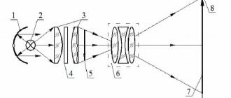
Principle of operation
The Tesla transformer consists of two windings - primary (Lp) and secondary (Ls) (they are more often called “primary” and “secondary”).
An alternating voltage is applied to the primary winding and it creates a magnetic field. With the help of this field, energy is transferred from the primary winding to the secondary. In this respect, the Tesla transformer is very similar to the most common “iron” transformer. The secondary winding, together with its own parasitic (Cs) capacitance, forms an oscillatory circuit that accumulates the energy transferred to it. Part of the time, all the energy in the oscillating circuit is stored in the form of voltage. Thus, the more energy we pump into the circuit, the more voltage we get.
A simple diagram of how a Tesla coil works.
Tesla has three main characteristics - the resonant frequency of the secondary circuit, the coupling coefficient of the primary and secondary windings, and the quality factor of the secondary circuit.
The reader should know what the resonant frequency of an oscillatory circuit is. I will dwell in more detail on the coupling coefficient and quality factor.
The coupling coefficient determines how quickly energy is transferred from the primary winding to the secondary, and the quality factor determines how long the oscillating circuit can retain energy.
Seesaw analogy
In order to better understand how an oscillatory circuit accumulates energy, and where such a large voltage comes from in a Tesla, let’s imagine a swing that a huge man is swinging. The swing is an oscillatory circuit, the man is the primary winding. The speed of the swing is the current in the secondary winding, and the height of the rise is our long-awaited voltage.
The man pushes the swing, and thus transfers energy into it. And so, after a few pushes, the swing swayed and flew as high as possible - it had accumulated a lot of energy. The same thing happens with a Tesla, only when there is too much energy, an air breakdown occurs, and we see our beautiful streamers.
Naturally, the swing should not be swayed anyhow, but in exact accordance with its own vibrations. The number of times the swing oscillates per second is called the “resonant frequency.”
The section of the swing's flight path during which the man pushes it determines the coupling coefficient. If a man constantly holds the swing with his hefty hand, he will swing it very quickly, but the swing can only deviate by the length of the man’s arm. In this case, the coupling coefficient is said to be equal to one. Our swing with a high coupling coefficient is an analogue of a conventional transformer.
Now consider a situation where a man pushes the swing just a little. In this case, the coupling coefficient is small, and the swing deviates much further - the man now cannot hold it. The swing will take longer to swing, but even a very frail man can handle it, pushing it a little each period of oscillation. Such a swing is an analogue of the Tesla transformer. The higher the coupling coefficient, the faster energy is pumped into the secondary circuit, but at the same time the output Tesla voltage is lower.
Now let's look at the quality factor. Good quality is the opposite of friction in a seesaw. If the friction is very high (low quality factor), then the man will not be able to swing them with his weak pushes. Thus, the coupling coefficient and the circuit quality factor must be matched to achieve the maximum swing height (maximum streamer length).
Since the quality factor of the secondary winding in a Tesla transformer is not a constant value (it depends on the streamer), it is not very easy to reconcile these two values, and therefore they are simply selected empirically. A brief description of the operating principle of the transformer can be seen in the video.
Similar to a swing
To better understand the accumulation of large potential differences in a circuit, imagine a swing being rocked by an operator. The same oscillation circuit, and the person serves as the primary coil. The swing stroke is the electric current in the second winding, and the rise is the potential difference.
The operator swings and transmits energy. Over several times they accelerated greatly and rose very high; they concentrated a lot of energy in themselves. The same effect occurs with a Tesla coil, an excess of energy occurs, a breakdown occurs and a beautiful streamer is visible.
You need to oscillate the swing in accordance with the beat. Resonance frequency is the number of oscillations per second.
The length of the swing trajectory is determined by the coupling coefficient. If you swing a swing, it will swing quickly and move away exactly the length of a person’s arm. This coefficient is one. In our case, a Tesla coil with an increased coefficient is the same transformer.
A person pushes the swing, but does not hold it, then the coupling coefficient is small, the swing moves even further. It takes longer to swing them, but it doesn't require force. The coupling coefficient is greater the faster energy accumulates in the circuit. The potential difference at the output is less.
Quality factor is the opposite of friction, using the example of a swing. When friction is high, the quality factor is low. This means that the quality factor and coefficient are consistent for the highest swing height, or the largest streamer. In the transformer of the second winding of the Tesla coil, the quality factor is a variable value. It is difficult to reconcile the two values; it is selected as a result of experiments.
Part three. Secondary winding.
We take a PEV wire with a diameter of 0.5 mm, take a sewer pipe with a diameter of 16 mm (the orange one), wind it turn to turn until the winding height is reached at 400 mm, cover the resulting mess with epoxy in several layers.
You can use PELSHO wire in silk insulation (if you can find it, lol), the quality factor of the coil will decrease due to an increase in the distance between the turns, but the electrical strength will increase, it is easier to coat it with epoxy and after coating the coil looks cool-black-gothic. All this sounds easy, but without a lathe with low speeds and preferably a smooth start, it takes a long time and is hemorrhagic. You can use your friend and a mop as a machine, yes. We insert a standard plug on top (alarm! You didn’t saw off the extension of the pipe to install the plug?), we make a hole in the plug (not a hole, but a hole! With a soldering iron, yes, yes), we attach an M6 pin through washers into it, and connect the upper end from below wire to the stud, then turn the coil over and pour half a liter of epoxy inside the pipe, hey.
From below we solder the winding wire to a wire in silicone insulation, about 300 mm long, attach it through two holes, insulate it, proffit.
Monsieur also painted it with alkyd enamel from a spray can. Because I could. As it turned out, this was, ahem, unnecessary, but more on that later.
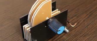
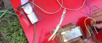
Necessary materials
- Let's take a car battery (or any other source of constant voltage 12-19 V) as a source;
- Copper wire (preferably enamel) with a diameter of 0.1 to 0.3 mm. and about 200 meters long;
- Another copper wire with a diameter of 1 mm;
- Two frames (dielectrics). One (for the secondary circuit) with a diameter of 4 to 7 cm and a length of 15-30 cm. The other (for the primary circuit) should be several centimeters larger in diameter and shorter in length;
- Transistor D13007 (you can use others identical to it);
- Pay;
- A few resistors of 5 - 75 kOhm, 0.25 W power.
SSTC (SSTC, Solid State Tesla Coil)
Tesla transformer, which uses semiconductors as a key element. Usually these are MOSFET or IGBT transistors. This type of transformers can operate in continuous mode. The appearance of the streamers created by this coil can be very different. This type of Tesla is the easiest to control (play music, for example).
Solid State Tesla Coil type.
Transformer design
The second point to consider when considering a Tesla transformer is the circuit. How exactly is the coil constructed? In fact, the design of this transformer can be very diverse, so now you will learn how its simplest version works, which you can then improve as you want.
So, the simplest Tesla transformer consists of several elements, namely an input transformer, an inductor, which includes a primary and secondary winding, as well as a spark gap, a capacitor and a terminal. Strictly speaking, the current begins its movement from the input transformer, which is the power source, from where it reaches the inductor through a spark gap and a capacitor, and from there it is transmitted to the terminal in a multiplied amount. Moreover, the terminal is often chosen so that it can best transmit such voltage, for example, it can be in the shape of a ball or disk. As you understand, this is the simplest Tesla transformer - the diagram is proof of this. There can be more elements in a Tesla coil. There may be, for example, a toroid, which is not described in this diagram, since it is not a key element. As for the main elements, they were all indicated.
Part two. Primary installation.
It is better to make the winding itself from a copper busbar with a width of 1.5x25mm, 8 meters can be bought for quite reasonable money.
1) We make 6 pieces of fasteners 2) We put them on epoxy (or wood glue, for example) on the top stool 3) we take a busbar, drill a hole on one side, solder a piece of copper wire about 400 mm long, with a cross-section of 25 squares. 3) We lay the bus in 8 turns, starting from the center, bringing the wire out from the beginning through the hole in the upper seat of the former stool to the place where we will have the motor with the disk. 4) On top of the same epoxy we glue a wooden block 10mm thick and wide and 22mm thick for final fixation of the tire. 5) On top of the strip, which is attached with two self-tapping screws, we fasten it with ties\wire\whatever is needed to form a closed circle of copper tube. 6) Profit!