The name Arduino is currently a sort of “fashionable” word for most radio amateurs and everyone who is more or less familiar with electronics, since this platform allows you to create electronic devices quickly and cheaply. The presence of an extensive online community of this platform makes it an ideal choice for those who have just begun their acquaintance with electronics and programming. Even people who do not have a technical education (and this is exactly who it was originally created for) will find it quite easy to master Arduino.
Why is this platform so relevant? How to get started with it? How can it improve your lifestyle? All these issues will be discussed in this article. To do this, we will learn how to install the Arduino IDE on your computer and load it with a small program that will blink an LED, which we will connect to the Arduino using a breadboard.
What is Arduino
Unfortunately, some novice radio amateurs consider Arduino a microcontroller, but this is not entirely true. Let's try to figure out what it is.
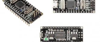
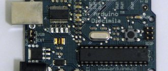
Arduino is an open source development platform that consists of an easy-to-use hardware and programming environment. The most common type of hardware is Arduino UNO, and the programming environment is called Arduino IDE. In addition to Arduino UNO, there are quite a lot of similar boards - Arduino Mega, nano, mini, but in this article, for training purposes, we will use Arduino UNO. And the Arduino IDE is exactly the software environment with which we will program the Arduino UNO board.
Where to buy Arduino Nano
Traditionally, foreign online stores offer the lowest prices. In Russia, prices will almost always be 20-200 percent higher, but you won’t have to wait about a month for your order.
Here are links to reliable Aliexpress suppliers:
| Arduino Nano CH340/ATmega328P MicroUSB with pin comb | Arduino RF-Nano board with integrated NRF24l01+2.4G wireless module | Arduino Nano with MINI USB port and ATmega328P CH340G 5V 16M chip |
| Nano V3 ATmega328/CH340G board option with Micro USB port from RobotDyn | Arduino Nano V3.0 Kit with Mini USB Cable | Ethernet Shield for Arduino Nano 3.0 - an excellent solution for smart home projects |
Installing Arduino IDE
Before you start working with Arduino, you need to install the Arduino IDE programming environment on your computer/laptop. All steps described below for installing this software environment will be focused on the Windows operating system; for other operating systems the sequence of actions will be approximately the same. If you have problems with other systems, help can be found at the following links - for Mac users and Linux users. Before you start installing the Arduino IDE, make sure that you have administrator rights on your computer - this will make the installation easier.
Step 1 . Download Arduino IDE from the official website - https://www.arduino.cc/download_handler.php.
Step 2 . Run the downloaded exe file.
Step 3 . In the window that opens, click on “I Agree” to agree to the terms of the Arduino license.
Step 4 . In the installation options window, check all the boxes (see figure).
Step 5 . In this step, you need to select where to install the Arduino IDE. The default installation path is Program files on drive C - it is highly recommended to leave this path.
Step 6 . In this step, you can watch the Arduino IDE being installed on your computer (see picture). Once the installation is complete, click the “completed” button.
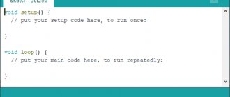
Step 7 . After the installation is complete, run the Arduino.exe file. An IDE window will open with a minimum of code inside it - see the picture.
Adding a User to the Arduino Port Usage Group
To avoid possible problems when using the Arduino IDE , add the system user to the dialout .
Arduino software if you get an error.
It may happen that when uploading a sketch you receive the following error:
“Error opening serial port...”
If you receive this error, you need to set the serial port permissions.
Enter the following command in the terminal:
$ ls -l /dev/ttyACM*
you'll get something like:
crw-rw— – 1 root dialout 188, 0 5 apr 23.01 ttyACM0
The data we need is “ dialout ” (this is the group owner of the file).
Now we just need to add our system user to the group:
$ sudo usermod -a -G dialout
Linux username You will need to log out and log back in for this to take effect.
In my case it's like this:
$ sudo usermod -a -G dialout smilojkovic
the IDE normally and download the code to your board or use the serial monitor.
Connecting your Arduino board to your computer
Once you have installed the Arduino IDE on your computer, the next logical step is to connect the Arduino UNO board to your computer. To do this, simply use the programming cable (blue) and connect it to the Arduino board and the USB port of your computer.
The blue programming cable can perform the following three functions:
- It powers the Arduino UNO board, that is, to ensure the execution of programs on it, you simply need to power it using a USB cable.
- The ATmega328 microcontroller located on the Arduino UNO board is programmed through it. That is, the program code is sent from the computer to the microcontroller via this cable.
- It can function as a serial communication cable, meaning it can be used to transfer data from the Arduino UNO to a computer - useful for program debugging purposes.
After you supply power to the Arduino UNO board, a small LED on it will light up - this indicates that power is supplied to the board. You may also notice another LED blinking - this is the result of the LED blinking control program that is loaded into your board by default by its manufacturer.
Since you are connecting the Arduino board to the computer for the first time, it will take some time for the drivers to install successfully. To check whether everything was installed correctly and detected, open the “Device manager” on your computer.
In Device Manager, open the “Ports” option “Ports (COM & LPT)”, click on it and see if your board is displayed correctly there.
It is worth noting that you should not pay attention to what port number is displayed on your Arduino board - it may, for example, look like CCH450 or something similar. This port number is simply determined by the board manufacturer and does not affect anything else.
If you cannot find the “Ports (COM & LPT)” option in Device Manager, this means that your board was not detected correctly by the computer. In most cases, this means a problem with the drivers - for some reason they were not automatically installed for your board. In this case, you will have to manually install the necessary drivers.
In some cases, the specified Device Manager option may show two COM ports for your board and you will not know which one is correct. In this situation, disconnect and reconnect the Arduino board to the computer - which of the COM ports will appear and disappear, which means that is the correct port.
You should remember that the COM port number will change every time you connect your board to the computer - don’t be alarmed, there’s nothing wrong with that.
Arduino LLC Upgrade Frequently Asked Questions
Which OS is compatible with Arduino LLC drivers?
Windows has a valid driver for Arduino LLC.
What is the reason for updating Arduino LLC drivers?
Updated drivers will unlock features, increase PC performance, and expand your hardware's functionality. Installing the wrong Arduino LLC drivers can cause system crashes, poor performance, and general instability.
How do you know when to update your Arduino LLC drivers?
We recommend updating Arduino LLC device drivers periodically, usually at least several times a year.
Why do some people ignore Arduino LLC driver updates?
Most people are afraid that they will cause a computer crash or error if they update Arduino LLC device drivers.
Loading LED Flashing Program
Now let's load our first program into the Arduino board using the Arduino IDE, which we just recently installed. The installed Arduino IDE contains several example programs that will be very useful for beginners. Let's open one of these example programs using the following path File -> Examples -> Basics -> Blink (as shown in the picture).
This will open the Blink program - its purpose is to make the built-in LED on the Arduino board blink. After opening the program, we need to select the correct Arduino board - to do this, select the menu item Tool -> Boards -> Arduino UNO/Genuino as shown in the figure below.
Next we must select the correct port for our board. Earlier we saw that our board had a COM13 port defined. In your case it may be a different port. But for our case under consideration, we must select the menu item Tools -> Port -> COM13.
If everything is done correctly, you should notice that the port number (in our case COM 13) will appear at the bottom of the screen. After this, you need to click the download button (highlighted in blue) to the Arduino board as shown in the figure below.
After clicking this button, you will see the message “Compiling sketch” and then if the program upload is successful, you will see the message “Done Uploading” as shown in the image below.
If at this stage you encounter any errors that are not discussed in this article, then you can try to find them in the article about the 10 most common errors when working with Arduino.
Now let's try to write a program that will light up an LED when a button is pressed.
7Loading sketches into Arduino memory
Now you can load the program into the board's memory. Connect the board to the computer, wait a few seconds while the board initializes. Click the Upload , and your sketch will be written to the memory of the Arduino board.
The LED should start blinking cheerfully at you every 2 seconds (1 second on, 1 second off). Below is the code for our first Arduino program. void setup() {
// initialization block pinMode(13, OUTPUT);
// set pin 13 as output. } void loop() {
// loop that repeats endlessly as long as the board is turned on: digitalWrite(13, HIGH);
// apply a high level to pin 13 - light the LED delay(1000); // for 1000 ms = 1 sec. digitalWrite(13, LOW); // apply a low level to pin 13 - turn off the LED delay(1000); // for 1 sec. }
// then the cycle repeats
Read the comments in the text of the program - they are enough to understand our first experiment. First we describe the initialization block setup()
, in which we set the initial values of the variables and the functions of the Arduino pins.
What follows is an endless loop()
that repeats over and over again as long as power is supplied to the board.
In this cycle we perform all the necessary actions. In this case, we turn on and turn off the LED. The delay()
operator specifies the execution duration (in milliseconds) of the preceding operator.
The digitalWrite()
statement tells the Arduino which pin to apply voltage to, and exactly what voltage level. Your first sketch is ready!
Helpful advice
There are many sites on the Internet dedicated to working with Arduino family boards. Read, master, don’t be afraid to experiment and learn new things! This is a fun and rewarding activity that will bring you a lot of pleasure.
Connection diagram
Shown in the following figure.
We will connect the button to the second pin of the Arduino, that is, one end of the button will be connected to the second pin of the Arduino, and the other to the ground. That is, whenever we press a button, ground will be supplied to the second pin of the Arduino.
The LED is connected to pin 3 through a 1 kOhm resistor. That is, the cathode of the LED is connected to ground, and the anode is connected to pin 3 of the Arduino through a resistor.
Example projects with Arduino Nano
There are a huge number of projects using the Nano board. In theory, you can easily add a Nano board to any project for Arduino Uno and you won’t have to change anything in the code. That is why, often after debugging a project on a “large and convenient” Uno, the circuit is converted to nano and a “reduced” controller is used in the working version, which is easier to make miniature.
Connecting LEDs to Arduino Nano
You can use LED flashing as a test program to check the operation of the board. The board has a built-in LED L, which is usually used for first projects. But you can also connect an external LED to output D13. We, of course, do not forget that the LED must be connected through a resistor so as not to burn it and damage the board. The anode of the LED is connected to a resistor, which is connected to the output of D13. The LED cathode is to ground. Here is an example diagram:
The Arduino IDE has an example that involves blinking an LED. To do this, go to the menu File>>Samples>>1. Basics>> Blink and download the example. After unloading the pod, the Arduino will execute the program, blinking the LED once per second.
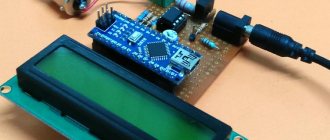
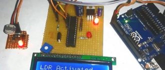
Connecting LCD 1602 to Arduino Nano
The LCD 1602 screen is quite common, there are various types of shields for it, but it can also be connected directly to Arduino. To connect the display to the board you need an Arduino Nano, a development board, an LCD 1602 screen and connecting wires.
The choice of pins to which you want to connect the display can be anything. For example, the following configuration will be selected: the RW pin from the display is connected to ground, the 4th display pin is connected to A0 on Arduino, the 6th pin is connected to E (Enable), the 11th to 14th pins are connected to D4-D7. The screen is connected. In order to start writing code, you need to connect the LiquidCrystal library. It also contains a test sketch that will allow you to check the functionality of the installation. The code is located at Arduino\libraries\LiquidCrystal\examples\HelloWorld\HelloWorld.ino, in the sketch you only need to change the numbers of the pins to which the screen is connected. If everything is connected correctly, the message will light up on the monitor.
Connecting nrf24l01 to Arduino Nano
The nrf24l01 radio module is used in cases where it is necessary to receive data from sensors that are located at a distance from the control device. The module is easy to use and easily connects to Arduino.
The connection to Arduino Nano is shown in the figure. The ground from the board is connected to the ground of the module, the voltage is 3.3V, the 3rd pin (CE) is to D9, from 4 to 7th is to D10-D12. For the 3rd and 4th contacts, you can use any pins, the main thing is to indicate this later in the code.
A capacitor can also be soldered to the radio module between the ground and power outputs, which will reduce noise and make the device more stable.
There are several libraries for working with the module. The most common libraries are RF24 and Mirf. The choice of a particular library is determined by ease of use.
Review of popular shields for Arduino Nano
Expansion boards (or arduino shield) are used to solve various problems and simplify projects.
All the necessary electronic components are installed on the expansion board, and interaction with other controllers is carried out through standard Arduino contacts. Nano Uno shield is a shield that allows you to turn a Nano board into a Uno. The platform has various connection pads, a reset button and a power socket.
| Several options for Arduino Nano shields | Multifunctional expansion board for Arduino Nano | Expansion board v4 with built-in stepper motor driver modules |
| Very convenient adapter for Arduino Nano with reliable connectors | Arduino Nano module with L298P 2A motor driver on board | Data logger for Nano v3.0 with SD module and real time clock on board |
Arduino Nano Ethernet Shield - used to provide networking via Ethernet. Similar to the same shield for Arduino Uno, but smaller in size and much more convenient in real projects.
Arduino Nano Motor Shield is a shield that is used in robotics projects to connect motors and motors to the Arduino board. Its main task is to provide control of devices that consume large (compared to Arduino) current. Also, using the shield, you can control the power of the motor and change its direction of rotation. There are many models of Motor Shield boards; they all have a powerful transistor, heat sink components, circuits for connecting an external voltage source, and connectors for connecting motors.
Arduino Nano Sensor Shield is the most common platform. The shield is simple - its main task is to provide convenient connection to the Arduino board of other devices. The shield contains additional power and ground connectors, connectors for connecting an external voltage source, an LED and a reset button.
Arduino Data Logging Shield is a shield that allows you to write a log of data from sensors. It is also used as file storage or real time clock. To work with the shield, there is a special library that allows you to log information to a memory card.
Arduino Proto Shield is a platform for rapid prototyping or creating your own shield. These boards contain platforms for mounting the necessary components, a reset button, 2 LEDs and a connector for external power. With their help, you can increase the compactness of the device.
Program functions
Below is a list of the most commonly used functions when programming Arduino:
- pinMode – sets the pin to input or output mode;
- analogRead – reads the analog voltage at the analog input pin;
- analogWrite – writes analog voltage to the analog output pin;
- digitalRead – reads the value of a digital input pin;
- digitalWrite – sets the value of the digital output pin to high or low;
- Serial.print – writes data to the serial port in human-readable ASCII text.
Description of the software
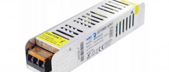
The Arduino Nano can be powered via a Mini-B USB connection, or from an unregulated 6 - 20 V (pin 30) or regulated 5 V (pin 27) external power supply. The source with the highest voltage is automatically selected.
The FTDI FT232RL chip receives power only if the platform itself is powered from USB. Thus, when operating from an external source (not USB), there will be no 3.3 V voltage generated by the FTDI chip, while the RX and TX LEDs blink only when there is a high level signal at pins 0 and 1.
Interesting read: How to make a microphone from a phone with your own hands.
The following pins are available for power access on the Arduino Nano:
- Vin: Voltage from external power supply (not related to 5V from USB or other regulated voltage). Through this pin you can both supply external power and consume current if an external adapter is connected to the device.
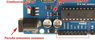
- 5V: The pin receives 5V from the board's regulator. This stabilizer provides power to the ATmega328 microcontroller. It is not recommended to power the device through the 5V pin - in this case, a voltage stabilizer is not used, which can lead to board failure.
- 3.3V: 3.3 V from the stabilizer of the FT232RL chip. The maximum output current is 50 mA.
- GND: ground.
- IOREF: The pin provides expansion boards with information about the operating voltage of the microcontroller. Depending on the voltage, the expansion board can switch to the appropriate power supply or use level converters, allowing it to work with both 5V and 3.3V devices.
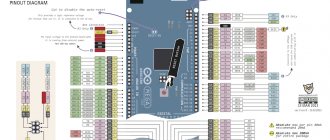
Pinout and circuit diagram of the arduino nano board.
Memory
The ATmega328 microcontroller has 32 KB of flash memory to store program code, 2 KB is used to store the bootloader. ATmega328 has 2 KB RAM and 1 KB EEPROM.
Input Output
Each of the Nano's 14 digital pins can be configured as an input or output using the pinMode(), digitalWrite(), and digitalRead() functions. The pins operate at a voltage of 5 V. Each pin has a load resistor (standard disabled) of 20-50 kOhm and can pass up to 40 mA. Some pins have special functions:
- Serial Bus: 0 (RX) and 1 (TX) – The pins are used to receive (RX) and transmit (TX) TTL data. These pins are connected to the corresponding pins of the FTDI USB-to-TTL serial bus chip.
- External Interrupt: 2 and 3 – These pins can be configured to trigger an interrupt on either a low value, a rising or falling edge, or when a value changes. See the attachInterrupt() function for details.
- PWM: 3, 5, 6, 9, 10, and 11 – Either pin provides 8-bit PWM using the analogWrite() function.
- SPI: 10 (SS), 11 (MOSI), 12 (MISO), 13 (SCK) – These pins provide SPI communication, which, although supported by the hardware, is not included in the Arduino language.
- LED: 13 – Built-in LED connected to digital pin 13. If the pin value is high, the LED is lit. The Nano platform has 8 analog inputs, each with a resolution of 10 bits (i.e., can take 1024 different values). By default, the pins have a measurement range of up to 5 V relative to ground, however it is possible to change the upper limit using the analogReference() function.
- I2C: 4 (SDA) and 5 (SCL) – The pins provide I2C (TWI) communication.
- AREF – Reference voltage for analog inputs. Used with the analogReference() function.
- Reset – A low signal on the pin resets the microcontroller. Typically used to connect a reset button on an expansion board, which blocks access to the button on the Arduino board itself.
Material on the topic: Homemade Kharchenko antenna: instructions and tips.
Board elements
Arduino Nano consists of many elements, including:
- microcircuits;
- passive elements (resistors, capacitors, diodes);
- connectors;
- regulators.
FT232R board chip
The chip allows you to connect the board via USB. The chip installed in the AN cannot work directly with the USB interface, so the FT232R converts it to a UART interface.
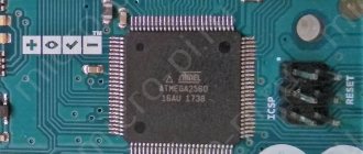
The heart of the platform is the ATmega328P microcontroller
ATmega328P is the main control element of the board. A sketch written by the programmer is loaded into it, and the controller sends commands to various elements of the board. For example, a microcontroller causes diodes to blink, relays to switch, and a piezoelectric element to make sounds.
LED indication
There are 4 LEDs built into the board, each of which has its own purpose:
- The RX and TX LEDs blink when data is being transferred via the UART.
- The L-diode lights up when a high signal level is applied to it, and turns off when the signal level is low.
- The ON LED lights up when there is power on the board.
Additionally, almost any pin of the microcontroller can be connected to other LEDs, 7-segment indicators or even displays.
Mini-USB connector
Using the mini-USB connector, the board can be connected to a personal computer. The AN can also receive power from external sources through this interface.
Linear Buck Voltage Regulator 5V
The LM1117MPX-5.0 microcircuit is used as a regulator. It converts the AN power signal into a power signal for the ATmega microcontroller and other logic elements that do not support power supplies greater than 5 V. For example, transistor-transistor logic (TTL) elements are powered by a signal of this magnitude.
ICSP connector for ATmega328
This interface allows you to download firmware to the microcontroller in a standard way. A special cable is connected at one end to the programmer connected to the PC, and at the other end to the ICSP connector.
Version nano v 3.0
This version is equipped with an ATmega328 microcontroller. Unlike its younger brother, it has twice the amount of non-volatile and flash memory. And it boasts a clock speed of 16 MHz.
It will be interesting➡ Review of the arduino uno board for Arduino
Characteristics
- Microcontroller: ATmega328
- Limit supply voltage: 5-20 V
- Recommended supply voltage: 7-12 V
- Digital I/O: 14
- PWM: 6 digital pins can be used as PWM pins
- Analog pins: 8
- Maximum current: 40 mAh from one pin and 500 mAh from all pins.
- Flash memory: 32 kB
- SRAM: 2 kB
- EEPROM: 1 kB
- Clock frequency: 16 MHz
Comparison table of most Arduino boards released to date.
Power connection
This microcontroller can be powered via the mini-USB port from a computer, power bank, or from an adapter connected to a power outlet. Also, the +5V pin is not only an output, but also an input. You can apply current to it and all this will work only on the condition that the voltage of the supplied current is strictly equal to five volts.
Expert commentary
Lagutin Vitaly Sergeevich
Engineer with a degree in Computer Software and Automated Systems, MEPhI, 2005–2010.
Ask a Question
You can also supply direct current with a voltage of 6 to 20 volts to the VIN pin. These are the limits! When a voltage of 20 volts is applied, the voltage regulator on the board will get very hot. The recommended voltage for power supply via the VIN pin is from 7 to 12 volts.