PWM operating principle
The pulse width modulated signal is generated in two ways:
- analog;
- digital.
With the analog method of creating a PWM signal, the carrier in the form of a sawtooth or triangular signal is supplied to the inverting input of the comparator, and the information input is supplied to the non-inverting input. If the instantaneous carrier level is higher than the modulating signal, then the output of the comparator is zero, if lower – one. The output produces a discrete signal with a frequency corresponding to the frequency of the carrier triangle or saw, and a pulse length proportional to the level of the modulating voltage.
As an example, the pulse width modulation of a linearly increasing triangular signal is given. The duration of the output pulses is proportional to the output signal level.
Analog PWM controllers are also available in the form of ready-made microcircuits, inside of which a comparator and a carrier generation circuit are installed. There are inputs for connecting external frequency-setting elements and supplying an information signal. The signal that controls powerful foreign keys is removed from the output. There are also inputs for feedback - they are needed to maintain the established control parameters. This is, for example, the TL494 chip. For cases where the consumer power is relatively small, PWM controllers with built-in switches are produced. The internal key of the LM2596 chip is designed for current up to 3 amperes.
The digital method is carried out using specialized chips or microprocessors. The pulse length is regulated by an internal program. Many microcontrollers, including the popular PIC and AVR, have a built-in module on board for hardware implementation of PWM; to receive a PWM signal, you need to activate the module and set its operating parameters. If such a module is missing, then PWM can be organized using a purely software method, it is not difficult. This method provides greater capabilities and greater freedom due to flexible use of outputs, but uses more controller resources.
A Simple Way to Improve Your PWM DAC
We shouldn't get discouraged by compromise #2, because there is an easy way to get more performance out of an RC filter: simply increase the PWM frequency! Remember that the spectrum of a PWM signal in the band from DC to carrier frequency is empty. Thus, a higher carrier frequency means a wider bandwidth in which the filter's frequency response can gradually roll off - same filter, same settling time, greater attenuation. Let's go back to our RC filter with fav ≈ 50 kHz and increase the carrier frequency to 10 MHz. Here are the results:
Figure 17 – Voltage settling time at the output of a PWM-based DAC with a clock frequency of 10 MHz with an RC filter with a cutoff frequency of 50 kHz
Figure 18 – Ripple at the output of a PWM-based DAC with a clock frequency of 10 MHz with an RC filter with a cutoff frequency of 50 kHz
The settling time is only about 15 µs and the ripple is only 25 mV (compared to 2.15 V when we used a 50 kHz filter and a 100 kHz carrier frequency).
PWM signal characteristics
Important characteristics of a PWM signal are:
- amplitude (U);
- frequency (f);
- duty cycle (S) or duty cycle D.
The amplitude in volts is set depending on the load. It must provide the rated supply voltage of the consumer.
The frequency of the pulse width modulated signal is selected based on the following considerations:
- The higher the frequency, the higher the control accuracy.
- The frequency should not be lower than the response time of the device controlled using PWM, otherwise noticeable ripples of the controlled parameter will occur.
- The higher the frequency, the higher the switching losses. It occurs due to the fact that the key switching time is finite. In the locked state, the entire supply voltage drops across the key element, but there is almost no current. In the open state, the full load current flows through the switch, but the voltage drop is small, since the throughput resistance is a few ohms. In both cases, power dissipation is negligible. The transition from one state to another occurs quickly, but not instantly. During the unlocking and locking process, a large voltage drops on a partially open element and at the same time a significant current flows through it. At this time, power dissipation reaches high values. This period is short, the key does not have time to warm up significantly. But with increasing frequency, such time intervals per unit time become larger, and heat losses increase. Therefore, it is important to use fast elements to build keys.
- When controlling an electric motor, the frequency has to be moved beyond the human audible range - 25 kHz and above. Because at a lower PWM frequency an unpleasant whistle occurs.
These requirements are often in conflict with each other, so the choice of frequency in some cases is a search for a compromise.
The amount of modulation is characterized by the duty cycle. Since the pulse repetition rate is constant, the duration of the period is also constant (T=1/f). A period consists of a pulse and a pause, having a duration of timp and tpause, respectively, and timp+tpause=T. The duty cycle is the ratio of the pulse duration to the period – S=tpulse/T. But in practice it turned out to be more convenient to use the inverse value - the duty cycle: D=1/S=T/timp. It is even more convenient to express the fill factor as a percentage.
Ripple and response at one pole
Let's see what quality DAC we can get using a simple RC filter. Let's start with the cutoff frequency (denoted fcp) in the middle of the band from the DC component to the carrier frequency:
\(f_{avg}=50\ kHz=\frac{1}{2\pi RC};\ select\ C=10\ nF\ \ \Rightarrow\ \ R\approx318\ Ohm\)
Figure 7 – Simulation diagram in LTspice: PWM signal generator and RC low-pass filter
Figure 8 – Voltage ripple obtained at the output of the low-pass filter
Not very good... Obviously we need more attenuation than we have now. Let's move the cutoff frequency by 1 kHz:
Figure 9 – Simulation diagram in LTspice: PWM signal generator and RC low-pass filter with a cutoff frequency of 1 kHz
Figure 10 – Settling time of the voltage obtained at the output of a low-pass filter with a cutoff frequency of 1 kHz
The ripple is now significantly reduced, but you may have noticed that we have a new problem: the output signal is taking a long time to reach the required DAC voltage. This is because higher resistance in an RC filter not only lowers the cutoff frequency, but also increases the time constant - higher resistance means less current flows to the capacitor and hence the capacitor charges more slowly. The following graph helps show the limitation this action places on the DAC:
Figure 11 – Voltage settling time
What you're seeing in this graph is a pretty poor "settlement time", which is a characteristic that shows how quickly the DAC can settle its output to the new programmed voltage. The graph shows that when the output signal is increased or decreased by half the full scale range, this particular circuit results in a settling time of almost 1 ms. Don't get me wrong, in many applications 1ms would be perfectly acceptable, but it doesn't change the fact that this settling performance is nothing compared to what you'd expect to see from a typical DAC.
The above results lead us to the first of two major trade-offs involved in designing a PWM-based DAC.
- Tradeoff #1: Lower cutoff frequency means less ripple and longer settling time; a higher cutoff frequency means more ripple and shorter settling time. Therefore, you should think about your application and decide whether you want the DAC to respond faster to changes or be less susceptible to output ripple.
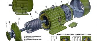
DC motor control using H-bridge
If we consider the principle of operation, then the H-bridge is a logical circuit of four logical elements (relay or semiconductor type), capable of switching to two states (open and closed). This example considers a bridge assembled on semiconductors. By simply changing the pairwise state of these elements, the motor will rotate in one direction or the other without the need to switch its contacts.
This device received its name due to its external resemblance to the letter “H”, where each pair of transistors is located in the vertical elements of the letter, and the directly controlled motor itself is located in the horizontal. An example of an elementary H-bridge of four transistors is shown in the figure below. By opening and closing the desired circuit elements in pairs, you can pass current through the windings in opposite directions.
H-bridge circuit
Look at the figure, in this circuit the motor power is controlled from terminals A and B, to which the control potential is applied.
The principle for determining the direction of rotation in an H-bridge is as follows:
- when a pulse is applied to the bases of transistors Q1 and Q4 to open the transition, current flows through the motor windings in one direction;
- when a pulse is applied to the bases of transistors Q2 and Q3 to open the transition, the current will flow in the opposite direction compared to the previous one and a reverse movement will occur;
- pairwise opening of transistors Q1 and Q3, Q2 and Q4 leads to braking of the rotor;
- opening transistors in the sequence Q1 and Q2 or Q3 and Q4 is completely unacceptable, since it will lead to a short circuit in the circuit.
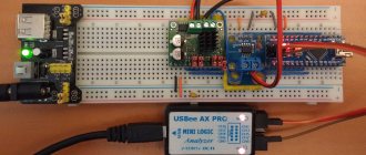
By using an H-bridge circuit to control the operation of a DC motor, you can implement a complete set of operations for an electrical machine without the need to reconnect its terminals. Due to the complexity of selecting transistors and connecting them to an H-bridge circuit, it is much easier to use existing drivers that have this function. Among them, the most popular are the L293D and L298N drivers.
Comparing both drivers, it should be noted that the L298N is superior to the L293D both in terms of performance and available options. Despite the fact that the L293D is a cheaper model, the L298N, due to significant advantages, has begun to be used much more often. Therefore, in this example we will look at the principle of motor control using the L298N driver and Arduino board.
Third example
And, of course, we’ll try to control all the LEDs one by one:
#define BLUE 9 #define ORANGE 10 #define GREEN 11 void setup() { pinMode(BLUE, OUTPUT); pinMode(ORANGE, OUTPUT); pinMode(GREEN, OUTPUT); } void loop() { for (int i=0; i<256; i++) { analogWrite(BLUE,i); delay(10); } analogWrite(BLUE,0); for (int i=0; i<256; i++) { analogWrite(ORANGE,i); delay(10); } analogWrite(ORANGE,0); for (int i=0; i<256; i++) { analogWrite(GREEN,i); delay(10); } analogWrite(GREEN,0); }
How to increase the frequency and bit depth of Arduino PWM
There is no way to change the Arduino PWM frequency without directly managing the memory at a low level. Let's look further at how to change the timer operating mode to increase the Arduino PWM frequency. Timer 0 is used to calculate time, i.e. delay and millis functions. Increasing the frequency on Timer 0 will break any time-saving functions that may be used in the sketch.
To increase the Arduino bit capacity on analog outputs 9 and 10, let’s change the frequency of Timer 1 without the library. The maximum PWM frequency can reach 62,500 Hz on Arduino Uno and Nano boards. To do this, in the void setup() procedure you need to add the appropriate command from the table below.
| Permission | PWM frequency | Mode setting commands |
| 8 bit | 62,500 Hz | TCCR1A = TCCR1A & 0xe0 | 1; TCCR1B = TCCR1B & 0xe0 | 0x09; |
| 7,812.5 Hz | TCCR1A = TCCR1A & 0xe0 | 1; TCCR1B = TCCR1B & 0xe0 | 0x0a; | |
| 976.56 Hz | TCCR1A = TCCR1A & 0xe0 | 1; TCCR1B = TCCR1B & 0xe0 | 0x0b; | |
| 244.14 Hz | TCCR1A = TCCR1A & 0xe0 | 1; TCCR1B = TCCR1B & 0xe0 | 0x0c; | |
| 61.04 Hz | TCCR1A = TCCR1A & 0xe0 | 1; TCCR1B = TCCR1B & 0xe0 | 0x0d; |
The maximum Arduino PWM frequency is 62,500 Hz.
Arduino Pulse Width Modulation
PWM, in English Pulse-Width Modulation (PWM) is the control of power on the load by changing the duty cycle (width) of pulses at a constant frequency and amplitude of the signal. The following graph shows that for different values in the analogWrite function, the amplitude of the pulses remains constant, but the width of the pulses changes. The signal power determines the duty cycle of the pulse.
Schedule. Signal parameters, PWM duty cycle
There are two areas of application of pulse width modulation:
1. PWM is used in power supplies, power regulators, etc. The use of PWM on the Arduino Nano makes it possible to significantly simplify the control of the brightness of light sources (LEDs, LED strips) and the rotation speed of the motors.
2. PWM is used to receive an analog signal. A digital-to-analog converter (DAC) on Arduino is easy to implement, as it requires a minimum of radio elements - just one RC chain of a resistor and capacitor is enough.
How to increase the frequency and bit depth of Arduino PWM
There is no way to change the Arduino PWM frequency without directly managing the memory at a low level. Let's look further at how to change the timer operating mode to increase the Arduino PWM frequency. Timer 0 is used to calculate time, i.e. delay and millis functions. Increasing the frequency on Timer 0 will break any time-saving functions that may be used in the sketch.
To increase the Arduino bit capacity on analog outputs 9 and 10, let’s change the frequency of Timer 1 without the library. The maximum PWM frequency can reach 62,500 Hz on Arduino Uno and Nano boards. To do this, in the void setup() procedure you need to add the appropriate command from the table below.
| Permission | PWM frequency | Mode setting commands |
| 8 bit | 62,500 Hz | TCCR1A = TCCR1A & 0xe0 | 1; TCCR1B = TCCR1B & 0xe0 | 0x09; |
| 7,812.5 Hz | TCCR1A = TCCR1A & 0xe0 | 1; TCCR1B = TCCR1B & 0xe0 | 0x0a; | |
| 976.56 Hz | TCCR1A = TCCR1A & 0xe0 | 1; TCCR1B = TCCR1B & 0xe0 | 0x0b; | |
| 244.14 Hz | TCCR1A = TCCR1A & 0xe0 | 1; TCCR1B = TCCR1B & 0xe0 | 0x0c; | |
| 61.04 Hz | TCCR1A = TCCR1A & 0xe0 | 1; TCCR1B = TCCR1B & 0xe0 | 0x0d; |
The maximum Arduino PWM frequency is 62,500 Hz.
Part 2: Controlling Brightness with a Potentiometer
Required Components
- Additionally you will need a potentiometer
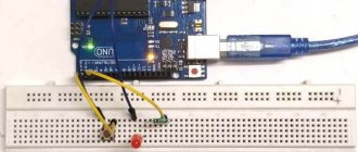
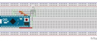
Scheme
Let's add a potentiometer to the circuit:
LED brightness control using potentiometer
We connect the middle leg of the potentiometer to analog input A0.
Sketch
/************************************************ ****** * (C) jarduino.ru 2022 * Studying Arduino through experiments. * * Experiment No. 3.2 Controlling the brightness of the LED using a potentiometer * * ************************************* ***************/ // Global constants and variables const int pinLed = 11; // port for the LED const int pinPot = A0; // port for the LED // setting up the board void setup() { Serial.begin(9600); // initialize the serial port pinMode(pinLed, OUTPUT); // set the LED pin to output mode // analog pins are already in input mode by default. } // main loop void loop() { static int nValOld = 0; static int nVal; // static variable to store the current LED brightness nVal = analogRead(pinPot); // display the nVal value in the debug window, and in order not to // react to interference, it will display the value only if it has changed by at least 3: if (abs(nValOld - nVal) > 3) { Serial.println(nVal); nValOld = nVal; } analogWrite(pinLed, nVal / 4); delay(10); // pause 0.01 sec. }
Result
When you rotate the potentiometer knob, you see in the serial port monitor how the voltage and brightness of the LED changes in accordance with it.
Explanation
In the program, we read the analog value set by the potentiometer and apply it to the digital PWM port to which the LED is connected. In accordance with the change in the PWM signal, the brightness of the LED also changes.
Please note that the maximum value for the PWM port is 255, and the maximum value for the analog port is 1024. Therefore, the read value must be divided by 4.
Individual tasks
- Change the third example so that after a smooth increase in brightness, the LEDs go out smoothly.
- Select the brightness ratio of the LEDs so as to achieve a white LED glow.
- Make a mood lamp out of the shield. The colors should shimmer randomly. Organize the main loop so that the pin number is first randomly selected, and then it smoothly lights up and goes out. To do this, you can use the random(min,max) function. To work with it, declare the variable int pin=0; and in a void loop() call this function pin=random(9,12);. It will write the value from 9 to 11 to the pin variable.
The rest of the articles in the series can be found here.
We will be very glad if you support our resource and visit our product store shop.customelectronics.ru.
Arduino Pulse Width Modulation
PWM, in English Pulse-Width Modulation (PWM) is the control of power on the load by changing the duty cycle (width) of pulses at a constant frequency and amplitude of the signal. The following graph shows that for different values in the analogWrite function, the amplitude of the pulses remains constant, but the width of the pulses changes. The signal power determines the duty cycle of the pulse.
Schedule. Signal parameters, PWM duty cycle
There are two areas of application of pulse width modulation:
1. PWM is used in power supplies, power regulators, etc. The use of PWM on the Arduino Nano makes it possible to significantly simplify the control of the brightness of light sources (LEDs, LED strips) and the rotation speed of the motors.
2. PWM is used to receive an analog signal. A digital-to-analog converter (DAC) on Arduino is easy to implement, as it requires a minimum of radio elements - just one RC chain of a resistor and capacitor is enough.