Features of crimping conductor from 8 and 4 cores
Before considering the technology for crimping copper conductors that make up the internal contents of a network cable, it is logical to familiarize yourself with the options for connecting terminals.
Network cable lug crimping diagrams
The tip is a plastic plug of the standard version of the 8P8C series connector. Such a connector (plug + socket) is often classified by computer network “experts” as an RJ45 connector.
However, such a classification is incorrect. But this is for general information.
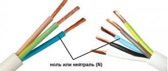
The appearance of the lugs (figures of eight) of the network cable, the contacts of which are subject to a crimping procedure when used for the first time. Once crimped, ferrules are not reusable
As can be seen from the series designation (8P8C), the plastic plug and socket are also 8-pin. These eight pins can be connected in different schematic patterns, depending on the type of cable connection.
Actually, there are two standards for wiring plug conductors T568A and T568B and two options for crimping them:
For ease of wiring of conductors and subsequent crimping, each core is marked with a specific color. Moreover, the veins of one pair are similar in color.
For example, the classic color of the first pair for the T568A standard for direct crimping of the first twisted pair: 1 - green-white; 2 - green.
The color standard for the cores of an eight-core network cable: the top picture is the T568A standard; The bottom picture is the T568B standard. As can be seen from the pictures, the difference in standards is noted by the color designation of some paired wires. 1 and 8 - core numbers
Direct and cross configuration
The difference between straight and cross crimping schemes for copper conductors should be obvious. The direct configuration provides a circuit solution when the core numbers (colors) match at two opposite ends of the network cable.
The cross configuration, accordingly, provides a circuit solution when a slightly modified pattern of matching conductors by numbers (colors) relative to each other is marked at the opposite ends of the network cable.
In particular, conductors 1, 2, 3 and 6 are swapped.
Cross-crimp configuration for 100 Mbps applications: 1 - white-orange / white-green; 2 - orange / green; 3 - white-green / white-orange; 4 – green / orange
Both crimping schemes provide for the arrangement of conductors on opposite end plugs, taking into account the correspondence of numbering, when the first wire is located opposite the eighth and vice versa - the eighth wire is located opposite the first.
In addition to these two schemes, there is another one, called “console”. In this case, the conductors along the end plugs are arranged in reverse order.
That is, the first conductor of one plug corresponds to the first conductor of the other plug, and, accordingly, the eighth wire at one end corresponds to the eighth wire at the opposite end.
Console circuit for crimping copper cores of a network cable. It differs in that the end plugs are located relative to one another in an inverted position when wire 1 = 1; wire 8 = 8
The purpose of a particular scheme
The specific application of the considered schemes is determined by the options for connecting computer equipment. As a rule, a direct configuration is used to connect a network card and a switch (hub).
A crossover configuration is usually used when there is a need to connect two network cards of personal computers. The same scheme was used for communications of outdated models of communicators (hubs).
It is worth noting an important detail: at the present stage of development of digital technology, the cross configuration has practically lost its significance. This is due to the development and implementation of technology for automatically detecting signal circuits of network terminals.
The cable configuration with a “cantilever” crimp is traditionally used for service purposes. For example, through such a scheme, a communicator (router) is configured using a personal computer
How to determine the grounding of wires, zero and phase, if there are no markings
Wires are not always color coded.
This makes it much more difficult to determine which wire goes where. But there is a way out of this too.
First, carefully inspect the wire - there are cases when the color differs along the entire length, and at the very end the desired shade is found.
If there is no such memo, electricians use improvised means to compare the designation of phase and neutral wires in electrics with the actual purpose of the cables.
Below we will consider three main ways to identify the required cables in single-phase and three-phase circuits if phase markings are missing.
Using an indicator screwdriver
The easiest way, available not only to electricians, but also to ordinary citizens, is to use an indicator screwdriver. It is enough to bring a screwdriver of this type to the wires inside the core, and the designation of the phase and (or) zero wires will immediately become clear.
If, when you touch the wire, the light located on the screwdriver lights up, this wire is a phase, and you need to be careful with it.
If the indicator does not light up when you touch the wire with a screwdriver, this means that this conductor is zero.
Using a control lamp
Don't have a tester or indicator screwdriver at hand?
Not a problem - you can make a test lamp to check the cables.
In this case, you do not need many tools and consumables - just a working incandescent lamp with a socket and two pieces of stranded wire.
Their length should be approximately 50 centimeters.
Connect the wires to the sockets of the socket, bring one free end of the wire to the metal, and touch the wire being tested with the other.
When it hits a phase, the light bulb will light up.
Using tester
If you have a tester or multimeter, then checking is greatly simplified. Read the instructions for the device and use it as directed.
The principle is simple - when the probe touches a wire, the display displays data that allows us to understand which wire is in front of us.
If this is a phase, the voltage will be shown on the display.
If you touch zero with the probe, nothing will be displayed on the display, or there will be voltage, but it will be insignificant.
Step-by-step instructions for crimping a network cable
Considering that cable connections are used quite often in a variety of conditions, including domestic ones, the question of how to crimp a twisted pair cable onto 8 cores is quite relevant.
Moreover, if not specialists are taken into account, but ordinary users - owners of personal computers.
Let's look at this simple process to make things easier for potential home network circuit builders.
To perform crimping work you will need a special tool:
The first two tools with exotic names are a special press, reminiscent in design of ordinary electrician's pliers and a cutter for removing cable insulation.
In essence, the cutter is an ordinary knife, with the only difference being that it is additionally equipped with recesses for removing the insulating coating.
How to determine the phase?
The phase wire (L) can be marked by the factory in one of the following colors:
Basically, phase wires are black, brown or white.
Important!
Color marking of electrical wires in this area has many nuances and often beginners have to face a number of questions
Such as:
- “What does the abbreviation PEN mean?”;
- “How to find grounding, phase and zero if the insulation has no color or has a non-standard color?”;
- “How to indicate phase, grounding and zero yourself?”;
- “Are there still standards for the color of insulation?”
We will now give a simple and concise explanation for each of these questions!
Application of non-standard pressing methods
Considering that purchasing a special tool (the same crimper) requires money, some craftsmen practice a non-standard method of crimping wires. Use a regular electrician's screwdriver with a flat blade of suitable width and thickness.
Using such a screwdriver, the contact rods are pressed, sequentially pressing one at a time into the body of the plug.
The method with a screwdriver is “barbaric”, I must say, but it works. True, the quality of pressing is not always good, resulting in unstable operation of the network cable
How to specify L, N, PE yourself?
If there is no visual designation or it differs from the standard designation, it is best to mark all the elements yourself after the repair is completed. To do this, you can use colored electrical tape or heat shrink tubing. According to the requirements, the indication of the cores must be done at the ends of the conductor where the connection to the bus is made.
Thanks to the color markings, repairs are made easier not only for you, but also for the electrician, who will most likely carry out repair work on the home electrical network after you! We talked about the process of marking wires in the shield in a separate article.
Conclusions and useful video on the topic
The video below demonstrates a household version of working with cable crimping, the use of a special tool and a step-by-step process.
This video, although not entirely technically correct, will help you understand the essence of the process more fully.
The procedure for crimping the copper cores of a network cable can be studied theoretically without much difficulty. Meanwhile, even with theoretical knowledge, practical skill is required .
In fact, this skill is developed quite quickly even when faced with work for the first time. True, a novice master cannot do without ruining a couple of plastic forks - he will have to practice first. This is the law of practice.
The vast majority of cables have different colors of core insulation. This was done in accordance with GOST R 50462-2009, which sets the standard for ln marking in electrical installations (phase and neutral wires in electrical installations). Compliance with this rule guarantees fast and safe work for a technician at a large industrial facility, and also allows you to avoid electrical injuries during independent repairs.
Color marking of phase, neutral and ground
For wiring and installation of electrical networks in domestic and industrial facilities, multi-core cables are used, each wire inside of which is painted in a distinctive color. This is necessary, as already mentioned, to simplify the installation and maintenance of the network.
So, for example, if a network repair is carried out by a person who was not involved in its installation, he will immediately understand the working diagram by the color of the wire connected to devices and power supplies. Otherwise, it will be necessary to punch through zero and phase manually using a probe. This process is not easy even when checking new wires, and if it is necessary to repair old wiring, it will completely turn into a test, since earlier, in Soviet times, wires were not marked, and they were all covered with a black or white insulating sheath.
According to developed standards (GOST R 50462) and electrical installation rules, each wire in the cable, be it zero, phase or ground, must have its own color, which indicates its purpose. One of the main requirements of electrical installations is the ability to quickly and accurately determine the function of a wire in any section. Color marking is best suited to solve this problem.
The wire markings presented below are designed for AC networks and electrical installations (transformers, substations, etc.) with a solidly grounded neutral and a rated voltage of no more than 1 kV. Most residential and administrative buildings meet these conditions.
Protective and working neutral conductor
Zero or neutral on electrical diagrams is indicated by the letter N and is painted throughout in light blue or dark blue without additional color designations.
PE – protective zero contact or simply “ground”, has a characteristic color of green and yellow lines alternating along the wire. Some manufacturers paint it a uniform yellow-green shade along its entire length, but GOST R 50462-2009, adopted in 2011, prohibits the designation of grounding in yellow or green separately. In combination green/yellow, these colors can only be used in situations where they indicate grounding.
PEN wires used in today's outdated TN-C systems, where ground and zero are combined, have more complex markings. According to the latest approved standards, the main part of the wire throughout its entire length should be painted blue, and the ends and junctions should be painted with yellow-green stripes. It is also possible to use wires with opposite markings - a yellow-green wire with blue ends. It is rare to see such a wire in modern buildings, since the use of TN-C was abandoned due to the risk of electric shock to people.
- zero (zero working contact) (N) – blue or light blue wire;
- earth (zero grounding) (PE) – yellow-green;
- combined wire (PEN) – yellow-green with blue marks at the ends.
Phase wires
The cable design may contain several current-carrying phase wires. Electrical codes require that each phase be identified separately, so the colors used are black, red, grey, white, brown, orange, purple, pink and turquoise.
When installing a single-phase circuit connected to a three-phase electrical network, it is necessary that the color of the branch phase exactly matches the color of the phase contact of the supply network to which it is connected.
In addition, the standard requires that all wires used be unique in color, so a phase cannot have the same color as neutral or ground. For cables without color identification, markings must be applied manually - with colored insulating tape or casings.
In order not to be faced with the need to purchase heat-shrinkable tubing or electrical tape during installation (and not to complicate the diagrams with unnecessary symbols), you should decide what combination of colors will be used in all electrical circuits of the house, and purchase the required number of cables of each color before starting work.
Variety of colors of electrical cable insulation
The color marking of wires is varied and varies greatly for grounding, phase and neutral conductors. To avoid confusion, the PUE requirements regulate what color ground wire to use in the power supply panel, and what colors must be used for zero and phase.
If the installation work was carried out by a highly qualified electrician who knows modern standards for working with electrical wires, you will not have to resort to using an indicator screwdriver or a multimeter. The purpose of each cable core is deciphered by knowing its color designation.
What GOST and PUE say about color marking
The main document that you should rely on when producing or purchasing cables is GOST 31947-2012. Before its appearance, there was no uniformity and order in the field of color designation of electrical wiring.
Until now, in old houses you can find wires in the same sheath, the color of which cannot determine what is connected - “phase”, “zero” or “ground”.
Now it has become much easier to identify veins. Even without using a tester, you can determine which contact a particular core should be connected to - by the color of the polymer insulation
The above-mentioned GOST document states that the insulation of cable products should differ in color. A certain shade should cover the wire with a continuous layer - from beginning to end. It is impossible for one wire at the beginning of the bay to be blue and the end to be white; Intermittent painting is also prohibited.
The only vein that can have a two-color shell is the “ground”. Officially, it is assigned the green/yellow combination; these two shades cannot be used separately
The regulatory documents also contain recommendations for the use of various circuits for 3-core, 4-core and 5-core cables.
For example, when producing 3-core cables, the following combinations are welcome:
- brown – blue – green/yellow;
- brown – gray – black.
If the cable consists of 4 cores, then two standard color options are also recommended:
- brown – gray – black – green/yellow;
- brown – gray – black – blue.
The diagrams for a 5-core wire look like this:
- brown – gray – black – green/yellow – blue;
- brown – gray – 2 black – blue.
The blue color indicates the “zero” core.
It is not recommended to use only two colors - red and white.
There are special requirements for the distribution of colors of the grounding conductor: on any randomly selected piece of wire 1.5 cm long, one color must cover 30-70% of the insulation, the second color must cover the remaining area
The color must be applied firmly and be clearly visible.
If you turn to the second important document for electricians - the PUE, then in clause 1.1.29 and clause 1.1.30 you can also find information about the color of the phase-neutral-ground wires. More precisely, the data is not listed there, but there is a reference to GOST R 50462-92, which has long been replaced by a more recent edition of GOST R 50462-2009, which is still in force today
The material corresponds to the information set out in GOST 31947, but there are some clarifications. For example, wires that perform a dual function should be painted in a special way: if the zero worker is combined with the zero protective wire, then it is painted blue along its entire length and has green-yellow stripes along the edges.
Schematic representation of the color marking of conductors. Along with the color designation, the cores also have a letter: zero - N, protective - PE, combined zero + protective - PEN
Thus, all colors, with the exception of blue (cyan) and green/yellow, can be used to color the insulation of the phase conductor. This group includes white and red colors, which for some reason are not recommended for use by the 2012 edition of GOST.
An example of a three-core cable manufactured in accordance with GOST standards: green/yellow conductor is intended for grounding, blue – neutral, brown – phase
In Appendix A to GOST R 50462 there is a table in which you can find the letter designations of all colors. For example, the phase conductor of a 1-phase circuit (L) is painted brown, the color code is BN. Letter codes are used for black and white copies of diagrams that do not use different colors.
Ground wire color
From 01/01/2011 the color of the grounding (or grounding) conductor can only be yellow-green. This color marking of wires is also observed when drawing up diagrams on which such conductors are signed with the Latin letters PE. The coloring of one of the conductors on cables is not always intended for grounding - usually it is done if there are three, five or more conductors in the cable.
PEN wires with combined “ground” and “zero” deserve special attention. Connections of this type are still often found in old buildings, in which the electrification was carried out according to outdated standards and has not yet been updated. If the cable was laid according to the rules, then blue insulation was used, and yellow-green cambrics were put on the ends and joints. Although, you can also find the color of the grounding (grounding) wire exactly the opposite - yellow-green with blue tips.
Protective grounding is mandatory when laying lines in residential and industrial premises and is regulated by PUE standards and GOST 18714-81. The neutral grounding wire should have as little resistance as possible, the same applies to the grounding loop. If all installation work is carried out correctly, then grounding will be a reliable protector of human life and health in the event of a fault in the power line. As a result, correctly marking cables for grounding is critical, and grounding should not be used at all. In all new houses, wiring is done according to the new rules, and old ones are put in line for replacement.
Color marking according to PUE and GOST (wire colors)
The colors of wires in electrics are regulated by regulatory documents (PUE and GOST R 50462-2009).
According to the rules for the technical operation of electrical installations, each wire of the electrical wiring must be connected to a source of electricity in accordance with the symbol of the wires. All phases have their own color designations, that is, each wire has individual wire colors. When the cable contains braided cores of the same color, a letter designation should be placed at the outputs of each wire. The electrical distribution panel to which the power cable is connected is marked in a similar way.
The PUE rules for marking electrical wiring stipulate the following:
- When installing an electrical panel, it is assigned an identification name, or a serial number, which is entered into the general layout of the building's electrical network. The exception is when in an apartment building electrical panels are located individually in each apartment.
- A table is attached to the inside of the panel surface, which indicates all the consumers that are connected to this switchgear.
- After installing the panel and connecting the entire electrical distribution system, the installer must leave the assembly diagram to the consumer or attach it inside the panel room. In order to ensure that in the event of repair and installation work, there is no inconvenience when it is necessary to connect new consumers to the switchboard.
In addition, the PUE and PTEEP contain the following regulations:
- Each cable line has its own name or serial number.
- Cables laid in an open manner must have numbered tags attached.
- Automatic emergency shutdown devices are also marked with the electrical wiring connected to them.
According to the rules of GOST No. 23594, adopted in 1979. and still in force today, all conductor cable cores must be connected according to their color. On the plan diagrams they must be indicated by an individual letter or number. If the braid of the cable cores is one-color, then individual wires at the input and output are marked using tags, seals or multi-colored PVC tubes.
According to the PUE standards, the following colors of current-carrying conductors are allowed:
- red;
- brown;
- black;
- gray; white;
- pink;
- orange;
- turquoise;
- purple.
Colors for neutral wire
For “zero” (or zero working contact) only certain wire colors are used, also strictly defined by electrical standards. It can be blue, light blue or blue with a white stripe, regardless of the number of cores in the cable: a three-core wire in this regard will be no different from a five-core wire or with an even larger number of conductors. In electrical circuits, “zero” corresponds to the Latin letter N - it participates in closing the power supply circuit, and in circuit diagrams it can be read as “minus” (phase, respectively, is “plus”).
Determining the purpose of wires in the panel and electrical wiring
You can determine the phase in a single-phase panel using a tester, multimeter, indicator, or a probe in the form of a light bulb. You can determine the identity of each phase (A, B, C, or L1, L2, L3) by performing phasing using a phase meter.
Digital phase meter for phase determination
Guaranteed determination of zero (in systems with a solidly grounded neutral) is ensured by the absence of voltage on the wire and the presence of almost zero resistance between this conductor and the ground bus.
Carrying out measurements in the shield
The protective conductor PE (grounding), in the absence of color identification in the socket or junction box, can be determined by first disconnecting the zero in the panel and connecting a light bulb between the phase and the test wire.
Homemade electrician's measuring device - “control”
If an RCD is installed in the panel. then it will turn off immediately. If the RCD is not installed, then the 220 V light bulb should glow. If the glow is dim, then the grounding is of poor quality, and therefore unreliable.
Electrical installation culture
It is important not only to know the decoding of color identification, but also to consistently observe this marking when branching lines and their passage through various devices - circuit breakers, RCDs, contactors, etc. The execution of each power line along its entire length with one unique color indicates a high culture of electrical installation
An electrical panel assembled in this way will not only look aesthetically pleasing, but will also allow you to determine the passage of power circuits at a glance
The execution of each power line along its entire length with one unique color indicates a high culture of electrical installation. An electrical panel assembled in this way will not only look aesthetically pleasing, but will also allow you to determine the passage of power circuits at a glance.
High culture of electrical installation
Unfortunately, it is not always possible to purchase cable products with the required color of the current-carrying conductors. For example, in a five-wire cable, the phase conductors may be designated red, yellow, and green.
Moreover, a cable with single-color cores may be available. In this case, it is necessary to perform cable testing. followed by marking of endings.
Special markers for cable terminations
If the input into the shield is made with a cable with a non-standard coloring, then the ends of the conductors must be marked with the corresponding colors, and the power lines must be continued according to the chosen identification.
Possible errors when deciphering color markings
Non-standard color of wires, inconspicuousness or fading of colored endings on single-color cable cores can lead to incorrect decoding of color identification. Therefore, you need to choose a cable with clearly distinguishable colors, and it is better that the coloring be done along the entire length of the cable cores.
When working with such a cable, you can easily make a mistake
Sometimes cable manufacturers paint the insulation of current-carrying conductors only at the ends of the cable. If the cable is cut into shorter sections, then the individual cores must be tested.
Occasionally, several cores in a cable may have insulation of the same color. Very rarely, but there is a manufacturing defect, and the ends of the conductors are marked incorrectly.
Cable with single-color cores
To ensure that you avoid trouble, you must develop the habit of checking the cable used during installation - in addition to errors with coloring, there may be a wire break or a short circuit.
How to determine phase and zero with an indicator screwdriver
Colors for phase wires
These electrical wires require especially careful and “respectful” handling, since they are live, and careless touching can cause severe electric shock. The color marking of wires for connecting a phase is quite varied - you cannot use only colors adjacent to blue, yellow and green. To some extent, it is much more convenient to remember what the color of the phase wire may be - NOT blue or cyan, NOT yellow or green.
On electrical circuits, a phase is designated by the Latin letter L. The same markings are used on wires if color markings are not used on them. If the cable is intended to connect three phases, then the phase conductors are marked with the letter L with a number. For example, to draw up a circuit for a three-phase 380 V network, L1, L2, L3 were used. In electrical engineering, an alternative designation is also accepted: A, B, C.
Before starting work, you need to decide what the color combination of wires will look like and strictly adhere to the chosen color.
If this issue was thought through at the stage of preparatory work and taken into account when drawing up electrical wiring diagrams, you should purchase the required number of cables with cores of the required colors. If you still run out of the required wire, you can mark the wires manually:
- ordinary cambrics;
- heat-shrinkable cambrics;
- electrical tape.
About the standards for color marking of wires in Europe and Russia, see also this video:
Color of zero, neutral
The “zero” wire should be blue
. In the distribution board it must be connected to the zero bus, which is designated by the Latin letter N. All blue wires must be connected to it. The bus is connected to the input via a meter or directly, without additional installation of the machine. In the distribution box, all wires (except for the wire from the switch) of blue color (neutral) are connected and do not participate in switching. To the sockets, the blue “zero” wires are connected to the contact, which is designated by the letter N, which is marked on the back of the sockets.
The designation of the phase wire is not so clear. It can be either brown, or black, or red, or other colors besides
blue, green and yellow. In an apartment switchboard, the phase wire coming from the load consumer is connected to the lower contact of the circuit breaker or to the RCD. In switches, the phase wire is switched; during switching off, the contact closes and voltage is supplied to consumers. In phase sockets, the black wire must be connected to the contact marked with the letter L.
How to find ground, neutral and phase in the absence of a designation
If there is no color marking of the wires, then you can use an indicator screwdriver to determine the phase; upon contact with it, the screwdriver indicator will light up, but not on the neutral and ground wires.
You can use a multimeter to find ground and neutral. We find the phase with a screwdriver, fix one contact of the multimeter on it and “probe” the wires with another contact; if the multimeter shows 220 volts, this is neutral; if the values are below 220, then it is grounding.
Letter and numeric wire markings
The first letter “A” denotes aluminum as the core material; in the absence of this letter, the core is copper.
The letters “AA” denote a multi-core cable with an aluminum core and an additional braid made of it.
"AC" is indicated in case of additional lead braiding.
The letter “B” is present if the cable is waterproof and has an additional double-layer steel braid.
“BN” cable braid does not support combustion.
"B" polyvinyl chloride shell.
"G" does not have a protective shell.
“g” (lowercase) bare, waterproof.
“K” is a control cable wrapped with wire under the top sheath.
"R" rubber casing.
"NR" non-flammable rubber casing.
Wire colors abroad
The color marking of wires in Ukraine, Russia, Belarus, Singapore, Kazakhstan, China, Hong Kong and the countries of the European Union is the same: Ground wire - Green-yellow
Neutral wire - blue
phases are marked with different colors
The neutral designation is black in South Africa, India, Pakistan, England, but this is the case with old wiring.
Currently the neutral is blue.
In Australia it can be blue and black.
In the USA and Canada it is designated white. You can also find gray labeling in the USA.
The ground wire is yellow, green, yellow-green in color everywhere, and in some countries it may also be without insulation.
Other wire colors are used for phases and may be different, except for the colors indicating other wires.
13 ways to save electricity
Manual color marking
It is used in cases where during installation it is necessary to use wires with cores of the same color. This also often happens when working in old houses, in which electrical wiring was installed long before the advent of standards.
To avoid confusion during further maintenance of the electrical circuit, experienced electricians used kits that allow them to mark phase wires. This is also allowed by modern rules, because some cables are manufactured without color and letter designations. The place where manual marking is used is regulated by the rules of the PUE, GOST and generally accepted recommendations. It is attached to the ends of the conductor, where it connects to the bus.
Marking of two-core wires
If the cable is already connected to the network, then to search for phase wires, electricians use a special indicator screwdriver - its body has an LED that lights up when the tip of the device touches a phase.
Next, you will need a set of special tubes with a heat-shrinkable effect or insulation tape to mark the phase and zero.
The standards do not require such markings to be made on electrical conductors along their entire length. It is allowed to mark it only at the places of joints and connections of the necessary contacts. Therefore, if there is a need to apply marks on electrical cables without markings, you need to purchase materials in advance to mark them manually.
The number of colors used depends on the scheme used, but there is still a main recommendation - it is advisable to use colors that eliminate the possibility of confusion. Those. Do not use blue, yellow or green marks for phase wires. In a single-phase network, for example, the phase is usually indicated in red.
Marking three-wire wires
If you need to determine phase, zero and grounding in three-wire wires, you can try to do this with a multimeter. The device is set to measure alternating voltage, and then carefully touch the phase with probes (you can also find it with an indicator screwdriver) and the two remaining wires in series. Next, you should remember the indicators and compare them with each other - the phase-zero combination usually shows a higher voltage than phase-ground.
When phase, zero and ground are determined, markings can be applied. According to the rules, a yellow-green colored wire is used for grounding, or rather a core with this color, so it is marked with electrical tape of suitable colors. Zero is marked, respectively, with blue electrical tape, and the phase is any other.
Applying markings to the laid cable
Electricians often have to deal with a situation where it is necessary to repair an electrical panel or network, but the equipment is connected in such a way that it is not clear where the phase and neutral are located, and where the ground is. This happens when the installation of the system is carried out by an inexperienced person, without special knowledge, for whom not only the markings, but also the location of the cables inside the switchboard are incorrect.
Another reason for such problems is the outdated and irrelevant qualifications of electricians. The work is done correctly, but in accordance with the old standards, so for the specialist who comes as a “replacement”, it becomes necessary to “punch” with a tool where the zero is located and where the phase is.
There is no point in arguing about who is to blame and whether anyone should do the repairs themselves; it is better to decide how to apply the correct and understandable markings.
So, current standards establish that color markings on electrical conductors cannot necessarily be placed along their entire length. It is allowed to mark it only at the points of connection and connection of contacts. Therefore, if you need to mark cables without markings, you should buy a set of heat-shrinkable tubes or insulating tape. The number of colors depends on the specific circuit, but it is advisable to purchase a standard “palette”: zero - blue, ground - yellow, and phases - red, black and green. In a single-phase network, naturally, the phase is indicated by one color, most often red.
The use of colored electrical tape or heat-shrinkable casings is also suitable for situations where the existing wire does not meet the requirements of the PEU. For example, if you need to connect a four-core cable to a three-phase network with wires of white, red, blue and yellow-green. These wires can be connected in any order, but be sure to place cambrics or windings of electrical tape with the “correct” colors at the connection points.
In addition, you should remember the problematic situations described above when installing a new unit or connecting equipment. The lack of clear and understandable markings can significantly complicate further maintenance of the circuit, even for the person who installed it.
If you find that your distribution panel or network uses wire symbols that do not meet current requirements, do not rush to replace them. Before repair or dismantling, the wiring is subject to the standards that were in force at the time of its installation. Additionally, if the network is functioning properly, replacement is not required. And when commissioning a new (or converted old) electrical network, you will have to take into account and comply with all modern requirements and rules.
Share with friends:
Wire color identification
For the correct connection to work, it is imperative to know the colors of the wires and their designation. The diagram of the radio wires by color is shown in the photo. On all cars and radios (Pioneer, Sony and Kenwood and others) it is customary to use a certain color to indicate the identity of the wire. It is worth noting that the radio wires differ in color and in the presence or absence of a strip. So, all wires with a stripe are a minus, and those without a stripe are a plus.
- Battery negative – black;
- Battery plus – yellow;
- Ignition plus – red;
- Left front speaker – white and white with stripe;
- Right front speaker – gray and gray with stripe;
- Left rear speaker – green and green with stripe;
- Right rear speaker – purple with a purple stripe;
- Antenna – blue;
- Amplifier – blue with a stripe.
Color of wires plus (+) and minus (-) in DC networks
Diode Polarity
Is the red wire positive or negative? Such questions arise when working with DC electrical circuits.
Red
To remember which plus is red or black, they use the name of a well-known international organization - the Red Cross. This phrase suggests that red means plus.
Black
Black color indicates the negative conductor. These markings can be seen on typical household equipment:
- power supplies;
- audio, video equipment;
- other devices with electronic software control units.
Plus
The polarity of conductors must be observed when repairing standard electrical equipment of cars. In some situations, confusion with plus and minus is accompanied by a violation of the functional state.
Minus
The high power of connected consumers increases the responsibility for performing repair and adjustment work. In such situations, it is necessary to eliminate errors in determining polarity. Strong direct current is used to supply electricity:
- warehouse and municipal transport;
- lifting mechanisms;
- sensors and automation.
Wiring insulation colors
Certain regulations also apply to wires used in electrical wiring. Color designation is important for electricians and everyone else who has to work with live networks.
Let's take transformers as an example. As a rule, a three-phase network is used there. Moreover, each phase has its own color designation. It is in relation to three phases that electricians use the abbreviation ZhZK, because this is the easiest way to remember the location of the wires in it.
In a three-phase network, each phase has its own insulation color - yellow, green and red.
The first color is assigned to phase A, the second to phase B, and the third to phase C.
This rule applies to alternating voltage networks with a power of 220 V.
For operation of 380 V networks, a different color designation is used.
Typically the wire markings are as follows:
- A - white;
- B - black;
- C - red.
For the ground wire and the neutral wire, the color designation remains the same - yellow-green and blue.
It is worth remembering that the color of phase-type wires may change and have a different shade, but with regard to wires, zero and ground always comply with the established requirements.
Checking correct connection without color coding
Compliance with color coding during the connection process is necessary.
This can be done using several basic methods, in which the color designation does not play a special role. The main thing is that the electrical wiring is freely accessible and that you have several tools with which you can check the purpose of the cables.
Using a multimeter
If in DC networks with two wires it is immediately clear that the red color is a plus, then if a three-wire wire is found in the network, it is necessary to carry out an additional check.
A multimeter is used to test cables with three wires. Before using the device, carefully read its instructions - check that the probes are connected correctly, and switch the device to constant voltage mode. When using a machine that allows manual settings, use them if necessary.
After this, touch the probes to the contacts being tested and monitor the readings on the screen.
If you made a mistake while connecting the device, a minus will be displayed on the screen next to the readings.
This way you will understand that the poles are reversed.
Using LED
An LED can be successfully used to test a constant voltage network. To do this, find or purchase an LED of the right size.
The principle of operation is simple - when an LED touches a surface through which current flows, it lights up.
The glow depends on the quality of the LED.
All indicator screwdrivers work on this principle - an LED is built into their handle.
If you don’t have such a screwdriver or tester at hand, a regular LED will be the solution to the problem.
Pink wire
A set of wires for a car radio may contain a cable covered with a pink protective layer. The element is used on head units capable of playing video. Used to switch an external rear view camera, providing signal broadcast. When using this type of equipment, signal compatibility must be ensured, otherwise the display image will be upside down.
To provide power to the camera, a Reverse wire is used, which allows you to enable signal transmission when using reverse gear. The cord is connected to the power supply circuits for the reversing lamps. When using standard parking sensors, it is possible to connect the cable to the controller connector.
An additional harness can be used in the design of the head unit to reduce the sound volume when reverse gear is engaged. The same cable, covered with a yellow-black insulator, is responsible for turning off the broadcast when a phone call arrives. If the car is not equipped with a cell phone connection unit, the cord is not used.
The harness also includes 8 cables intended for connecting rear and front speakers. When using component acoustics, it is necessary to connect the elements to a common channel, while controlling the resistance and power. All negative outputs from the speaker coils must be fed to the appropriate connectors on the amplifier.
It is not allowed to combine the poles into a single line and short circuit the nodes to the car body.
To install the low-frequency speakers, a separate wire is used, laid independently. On some cars, the subwoofer is a standard device, located in the niche for the spare wheel or the internal cavity of its disk. Separate cables are used for switching; the color of the insulation depends on the vehicle model.
On standard radios there is a flat cable designed to transmit information to the display, located in a separate pocket on the instrument panel. The harness consists of a large number of wires covered with white and gray insulation. The protective layer ensures the solidity of the product. The cable is secured with special clamps that ensure reliable contact and protection from moisture.
Ground wire color
By modern standards, the ground conductor is yellow-green. It usually looks like yellow insulation with one or two longitudinal bright green stripes. But there are also transverse yellow-green stripes in color.
Grounding may be this color
In some cases, the cable may only have yellow or bright green conductors. In this case, the “earth” has exactly this color. It is displayed in the same colors on diagrams - most often bright green, but it can also be yellow. Signed on circuit diagrams or on ground equipment in Latin (English) letters PE. The contacts to which the “ground” wire must be connected are also marked.
Sometimes professionals call the grounding wire “neutral protective”, but do not be confused. This is an earthen one, and it is protective because it reduces the risk of electric shock.