Wire Classification Options
Wires are classified according to different indicators, for example, by cable cross-section and number of cores.
Conductors have two types of markings - color and alphanumeric. Using these designations, you can understand what the product is made of, what the purpose of the core is, what material it is and other important parameters.
Wires can be classified according to the following indicators:
- Number of cores Depending on the number of cores, the conductor can be used to provide power to an electric motor, distribute electrical wiring, and transmit electric current in power networks. The flexibility of the product also depends on the number of cores.
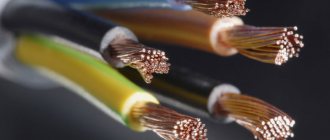
- Material. Copper is predominantly used to create current-carrying conductors, as it is more resistant and has good characteristics. Previously, aluminum was used - it quickly deteriorates, has a short service life and is inferior in properties to copper devices.
- Insulating layer. The conductor may or may not have insulation. It is made of dielectric material and protects the product from mechanical damage, external influences, and also protects people from electric shock.
- Section. The load that the cable can pass through itself depends on this indicator.
- Other indicators. Power, voltage, operating temperatures, operating conditions are also important for choosing a conductor.
Thanks to these properties, you can choose the right wire for different purposes.
Why do you need vein coloring?
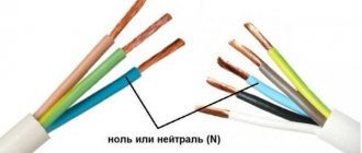
Color marking of wires allows you to quickly figure out what each wire is responsible for.
Novice craftsmen who are just learning the basics of electrical engineering cannot immediately determine whether the white wire is a plus or a minus. Coloring is important in identifying cores and is called marking.
Color marking of conductors is a necessity, allowing the master to quickly figure out what each core is responsible for. With its help you can understand what color the neutral wire is and where the phase is located. It also makes electronic circuits easier to read.
It is especially important to observe color markings when connecting to meters, machines, and devices. Without painting, it is difficult to figure out which device may have failed and which circuit it is connected to.
Manufacturers paint cables in certain colors established by the rules of electrical installations PUE. They strictly regulate which markings should be used for a particular core.
In addition, it is important to understand that the positive and negative contacts in the DC circuit have their own colors. What color the positive wire is is also determined by the rules.
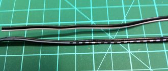
In the case of an unmarked cable of the same color, a label with information can be placed on the ends of the product (for example, on a heat-shrinkable tube).
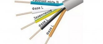
Grounding
The yellow-green wire is grounding. In circuit diagrams, grounding conductors are marked with the letters PE. In some older houses there are PEN wires in which the grounding is combined with the neutral conductor. If the cable was pulled according to the rules, wires with blue insulation were chosen, and only the ends and places of twists were yellow-green (thermal tubes were put on them). The thickness of the “zero” and grounding may be different. Often the thickness of these two conductors is less than the thickness of the phase conductor; this occurs when connecting portable devices.
When it comes to laying electrical wiring in multi-storey buildings and industrial premises, the norms of PUE and GOST 18714-81 come into force, requiring the mandatory installation of protective grounding. Grounding must have minimal resistance to compensate for the consequences of faults on the line and prevent harm to human health. That is, compliance with the standards for color marking of PUE wires is of paramount importance.
Phase color
When installing electrical wiring, it is the phase conductors that pose a particular danger. If a phase is touched, a person may receive an electric shock, which can be harmful or fatal. Painting in bright colors allows the master to determine that it is a phase conductor in front of him.
Usually the phase is colored red and black, but other colors can also occur (orange, brown, pink, purple, white, turquoise and others).
If the electrician does not know exactly what color the phase is, you can use the method of elimination. The neutral and ground wires have a strictly defined color, and then the remaining core is a phase.
In the diagrams, the phase is designated by the Latin letter L. If there are several of them, a number is added - L1, L2, L3 for three-phase networks of 380 V. The designation A, B and C is also found in electrical networks with three phases.
Tuesday, March 15, 2011
Charging a car battery is easy!
In the first case, the battery cannot be helped and it’s time to replace it with a new one. For the rest, a car charger will help, which can be purchased at any auto store. Usually it looks something like this:
Preparing to charge
- Connect the red charging clamp to the positive terminal of the battery (+).
- Connect the black charging clamp to the negative (-) terminal of the battery.
Note: If you have a so-called serviceable battery, then before charging you need to check that the electrolyte level covers the battery plates. If they are open, you need to add distilled (not from the tap) water until they are closed by 5-10 mm.
Ground wire color
Modern standards regulate the yellow-green color of the earth. The coloring can be done in the form of transverse yellow-green stripes or as yellow insulation with one or two longitudinal green stripes.
Some manufacturers produce a ground wire that is bright green or yellow. In this case, it is not difficult to identify the ground, since such colors are prohibited to indicate the phase. Similar markings are used on electrical circuits. Letter designation – RE.
Some experts incorrectly call the ground the “neutral and protective” wire. This may confuse others; you need to understand that under this name it is the earth wire that is hidden. It is, by definition, protective, as it helps protect a person from electric shock in the event of an emergency.
Mini USB pinout
This connection option is used only in early versions of the interface; in the third generation this type is not used.
Mini USB connector pinout
As you can see, the wiring of the plug and socket is almost identical to the micro USB, respectively, the color scheme of the wires and the contact numbers are also the same. Actually, the differences are only in shape and size.
In this article we have presented only standard types of connections; many manufacturers of digital equipment practice introducing their own standards; there you can find connectors for 7 pin, 8 pin, etc. This introduces certain difficulties, especially when the question arises of finding a charger for a mobile phone. It should also be noted that products are in no hurry to tell how the USB pinout is done in such contactors. But, as a rule, this information is easy to find on thematic forums.
Color of wires and buses for three-phase alternating current
Busbars and inputs to transformers in three-phase networks are painted in a certain way. Yellow is phase A, green is phase B, red is phase C.
Such networks have found their application in the following areas:
- Industry, construction, warehousing. Allows you to connect powerful industrial installations, unloading machines and other electrical equipment.
- Electrification of public transport. Trams and trolleybuses operate on a three-phase 380 V network.
- Electrical substations.
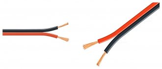
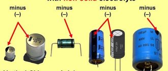
DC networks use only two wires - plus (positive bus) and minus (negative bus). Which wire is positive and which is negative can also be determined by the colors.
According to regulatory documents, the positive bus must be painted red, and the negative wire must be gray or black. The middle conductor is indicated in blue. You can see this designation of plus and minus on wires on various audio and video equipment, as well as other electronics.
In the case of a branch of a two-wire electrical network, the positive conductor must be colored in the same way as the plus on the three-wire network to which it is connected.
Features of working with electrical wires of different colors
There are cases when knowledge of phase and zero is not necessary. For example, when connecting a new outlet or replacing an old one. When connecting a plug to it, the polarity is not important and does not affect the performance of the device.
In situations where you need to connect a switch to a chandelier, you need to find out the phase and zero. The phase conductor is connected directly to the switch, and only the neutral conductor is connected to the light bulbs. Otherwise the switch will not work.
The use of conductors of different colors made the work of the craftsmen much easier and sped up the installation process. Also, the color designation made it possible to increase safety when working with live conductors.
Security measures
When working with electric current, the following precautions must be taken:
- Use devices only for their intended purpose;
- Do not turn on equipment with damaged wires and plugs, do not use faulty sockets;
- Do not touch wires or outlets with wet hands or while standing on a wet floor. When working in a room with high humidity, you need to use rubber gloves and a mat;
- Do not bend wires and cables;
- Before starting work, it is worth disconnecting the entire network;
- If the equipment sparks or starts to catch fire when turned on, do not touch it. It is necessary to turn off the power through the panel;
- If you have any doubts or fears, it is better to contact a specialist or choose a safer option, for example, determining the polarity using a potato rather than connecting to a device.
Most often in batteries, the red wire indicates positive, the black wire indicates negative, and there are no problems when working with electricity. However, today many countries use their own color designations or abandon them altogether, leaving the wires uniformly white. In order not to create emergency situations, it is worth checking the polarity first.
How to check the correctness of marking and wiring
All electrical work must be carried out in a de-energized room.
Color marking is simple and convenient, but you should not completely rely on its correctness. In addition, over time it can wear off, making it difficult to identify the wire. The difficulty lies in the old wires, which were monotonous - white or black. Therefore, before carrying out work, you should check what each core is responsible for.
It is important to de-energize the room before electrical installation. The wires at the ends should be cleaned a little, and only then checked with a tester. Otherwise, you may receive an electric shock.
Checking with an indicator screwdriver
Determining the phase wire using an indicator screwdriver.
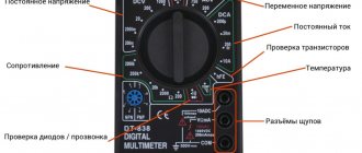
To work, you will need a tester. This could be a multimeter or an indicator screwdriver. It looks like a regular screwdriver, but there is an LED indicator at the end. Its handles are necessarily insulated. It’s easier to work with a screwdriver - just touch each wire, and if the probe hits a phase, the LED indicator should light up. This method is suitable for two-wire wires. The main disadvantage of determining the phase with an indicator screwdriver is the risk of false positives. It can respond to interference and show the presence of voltage where there is none.
You can buy the device at any hardware store. It is inexpensive and accessible to everyone, unlike professional testers.
Cost of indicator screwdriver
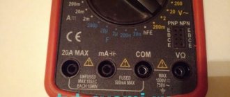
Checking with a multimeter
Checking wires with a multimeter
For a three-wire wire, you need a multimeter. Then you can go by elimination - find the exact phase using a screwdriver, and then use a tester to determine ground and zero.
There are two types of multimeters - digital and analog. The only difference is in the output of information, the accuracy of verification and the internal mechanism. The test method will not change depending on the type of tester. For a DIYer, you can buy an inexpensive multimeter with limited functionality.
The rotary switch must be set to a position greater than 220 V. Then you need to take two probes by the insulated handles and carefully touch the found phase wire with one probe, and the remaining conductor with the other. If 220 V or a little more lights up on the screen, then the wire found is zero. With land the value will be lower. The verification algorithm is similar.
Multimeter cost
Determination of ground, zero and phase using a test lamp
Using a test lamp to find the zero phase
This method is not recommended, since a tester and an indicator screwdriver are a more accurate and safer method. But if you don’t have the tools, you can do the following, doing everything very carefully:
- Screw the light bulb into the socket.
- Connect wires with stripped insulation to the cartridge terminals.
- Connect the wires being tested to the lamp wires one by one.
This method allows you to find the phase conductor. If the light bulb lights up, then one connected wire is a phase. Otherwise, the conductors are neutral and ground.
Other traditional methods of verification are prohibited. They are unsafe and may cause electric shock.
Self-labeling
There are times when markings are erased or missing/mixed up. Then, after ringing each conductor, you should independently indicate which core is responsible for what.
If sections of the wire are completely replaced, you can purchase cables of the required color. If it is not possible to purchase a suitable shade, you can make a mark on the ends using colored electrical tape or heat shrink tubing. The rules allow marking the conductor not along its entire length, but only at the points of connection to the busbars.