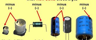
Color of wires plus (+) and minus (-) in DC networks
Is the red wire positive or negative? Such questions arise when working with DC electrical circuits.
Red
To remember which plus is red or black, they use the name of a well-known international organization - the Red Cross. This phrase suggests that red means plus.
Black
Black color indicates the negative conductor. These markings can be seen on typical household equipment:
Plus
The polarity of conductors must be observed when repairing standard electrical equipment of cars. In some situations, confusion with plus and minus is accompanied by a violation of the functional state.
Minus
The high power of connected consumers increases the responsibility for performing repair and adjustment work. In such situations, it is necessary to eliminate errors in determining polarity. Strong direct current is used to supply electricity:
Expert opinion
Viktor Pavlovich Strebizh, lighting and electrical expert
Any questions ask me, I will help!
Domestic passenger cars, as well as most cars of foreign brands, whose assembly is carried out in Russia, have batteries with straight polarity. If there is something you don’t understand, write to me!
Four-wire plug
There are two different options here.
- Ordinary headphones without a microphone and control buttons. 4 wires are connected to the plug: a minus from each copper-colored speaker and a plus (blue with red or green with red). For convenience, the negatives are twisted into one bundle and the result is three wires that need to be soldered to their specific places.
- Headset with microphone. Here the plug has 4 types of contacts: one from each speaker, one for the microphone, and there is room left for soldering a common wire or ground. Schematically, such soldering looks like this:
It should be noted that color marking may vary depending on the imagination of the manufacturer and is very arbitrary. The left channel wire can be green, white or blue. The right channel wire is always marked red. The common wire is copper (varnished or without insulation), but it can also be white if white is not used for the left channel.
Wire colors in electrical wiring
The color identification scheme is convenient not only for installation. As a rule, different contractors install and operate electrical wiring. Compliance with standards prevents errors during repair work and in the modernization process.
Something to remember! Domestic standards have changed several times over the past decades. Currently, the markings discussed above are used.
Color of zero working and zero protective wires
The color options for the shells will help you recognize the intended purpose of the conductors:
- blue – working zero;
- transverse or longitudinal combinations of yellow and green stripes - protective zero;
- main blue with a change to a combination of yellow and green stripes at the junctions - combined working and protective zero.
For your information. The last universal option can be done in the reverse way. The main part of the line is created from a combination of yellow and green stripes, with blue color applied at the junctions.
Four-wire plug
There are two different options here.
- Ordinary headphones without a microphone and control buttons. 4 wires are connected to the plug: a minus from each copper-colored speaker and a plus (blue with red or green with red). For convenience, the negatives are twisted into one bundle and the result is three wires that need to be soldered to their specific places.
- Headset with microphone. Here the plug has 4 types of contacts: one from each speaker, one for the microphone, and there is room left for soldering a common wire or ground. Schematically, such soldering looks like this:
It should be noted that color marking may vary depending on the imagination of the manufacturer and is very arbitrary. The left channel wire can be green, white or blue. The right channel wire is always marked red. The common wire is copper (varnished or without insulation), but it can also be white if white is not used for the left channel.
Types of USB connectors - main differences and features
There are three specifications (versions) of this type of connection that are partially compatible with each other:
- The very first version that has become widespread is v 1. It is an improved modification of the previous version (1.0), which practically did not leave the prototype phase due to serious errors in the data transfer protocol. This specification has the following characteristics:
- Dual-mode data transfer at high and low speed (12.0 and 1.50 Mbps, respectively).
- Possibility of connecting more than a hundred different devices (including hubs).
- The maximum cord length is 3.0 and 5.0 m for high and low transfer speeds, respectively.
- The rated bus voltage is 5.0 V, the permissible load current of the connected equipment is 0.5 A.
Today this standard is practically not used due to its low throughput.
- The dominant specification today is the second one. This standard is fully compatible with the previous modification. A distinctive feature is the presence of a high-speed data exchange protocol (up to 480.0 Mbit per second).
Due to full hardware compatibility with the younger version, peripheral devices of this standard can be connected to the previous modification. True, the throughput will decrease up to 35-40 times, and in some cases more.
Since these versions are fully compatible, their cables and connectors are identical.
- The 3rd generation universal bus was developed specifically to solve problems of insufficient bandwidth. According to the specification, this modification is capable of exchanging information at a speed of 5.0 Gbit per second, which is almost three times the reading speed of modern drives. Plugs and sockets of the latest modification are usually marked blue to facilitate identification of belonging to this specification.
Another feature of the third generation is an increase in the rated current to 0.9 A, which allows you to power a number of devices and eliminate the need for separate power supplies for them.
As for compatibility with the previous version, it is partially implemented; this will be discussed in detail below.
Black-red wire plus or minus
The disadvantage is the limited measurement accuracy. Under certain conditions, false positives cannot be ruled out.
Expert opinion
Viktor Pavlovich Strebizh, lighting and electrical expert
Any questions ask me, I will help!
The other ends of the wires are connected to the constant current source being tested, and the device is turned on. If it is a battery, then after connecting the wires you don’t need to do anything else for 15-20 minutes. If there is something you don’t understand, write to me!
Plug types and applications
Depending on the diameter of the working surface, connectors are divided into:
- Micro jack 2.5 mm . They are equipped with small portable devices such as phones, players, etc.
- Mini jack 3.5 . They are installed in household appliances: computers, TVs, etc. In addition, the pinout of jack 3.5 is extremely simple.
- Big jack 6.35 . Mainly used in professional equipment: electric musical instruments, powerful acoustic amplifiers, but can be built into budget equipment, such as karaoke microphones, metal detectors.
Based on the number of outputs (pin), jacks are divided into:
- Two-pin ( TS ). They transmit an asymmetrical signal, for example, a mono signal is sent to headphones or audio is recorded using a microphone.
- Three-pin ( TRS ). Using them, you can transmit both an asymmetrical signal, with pins 2 and 3 connected by a jumper, and a symmetrical one.
- Four-pin ( TRRS ). They can immediately transmit video and audio information. Modern phones, tablets, video players, etc. are mainly equipped with four-pin connectors.
- Five-position ( TRRRS ). An uncommon connector used by Sony in the Xperia Z smartphone for the simultaneous operation of two microphones, one of which works for noise reduction. TRRS compatible.
There are also two types of sockets: regular, created for a specific type of plug, and with a switch - when the pin is inserted, the device switches from one position to another.
Very often there are situations when Chinese collapsible plugs, which were installed instead of a monolithic broken “jack,” do not completely fit into the sleeve or are poorly fixed. Such situations are possible when the diameters of the sleeve and plug do not match. Therefore, when choosing such a plug, it is advisable for you to check its outer diameter with a caliper along the entire working length.
USB 3.0 pinout (types A and B)
- A – plug.
- B – nest.
- 1, 2, 3, 4 – connectors fully correspond to the pinout of the plug for version 2.0 (see B in Fig. 6), the colors of the wires also match.
- 5 (SS_TX-) and 6 (SS_TX+) connectors for data transmission wires via the SUPER_SPEED protocol.
- 7 – ground (GND) for signal wires.
- 8 (SS_RX-) and 9 (SS_RX+) connectors of wires for receiving data via the SUPER_SPEED protocol.
The colors in the figure correspond to those generally accepted for this standard.
As mentioned above, a plug from an earlier model can be inserted into the socket of this port; accordingly, the throughput will decrease. As for the plug of the third generation of the universal bus, it is impossible to insert it into the sockets of the early release.
Now let's look at the pinout for the type B socket. Unlike the previous type, such a socket is incompatible with any plug of earlier versions.
Wiring USB 3.0 type B
Digital signatures for contacts correspond to the description in Figure 8.
The color is as close as possible to the color markings of the wires in the cord.
Pinout diagrams by manufacturer
Apple audio pinout
- 1 - left
- 2 - right
- 3 - ground
- 4 - microphone
iPod Nano (4th, 5th Gen), iPhone (1st, 2nd, 3rd, 4th Gen), iPod Shuffle (3rd Gen), Cell Phone Connection iPhone headphone (handsfree)
Lenovo audio pinouts
1 - left 2 - right 3 - ground 4 - microphone
Lenovo Thinkpad Edge & X Series Notebook audio
Samsung audio pinouts
1 - left 2 - right 3 - ground 4 - microphone
Samsung Galaxy S I9000, S8500 Wave headset EHS60AVNBE / EHS60ANNWEGSTA / EHS60ANNBECSTD/ GH59-09752A headset Samsung Galaxy S2 i9100 headset should be compatible with Samsung Galaxy Note N7000, Samsung Galaxy Tab GT-P1000, P7100 Galaxy Tab 10.1, 4G LTE, C3530 , [ email protected] 350, Galaxy 551 i5510, Galaxy 550 I5500, E2330, I100 Gem, i220 Code, i350 Intrepid, I9003 Galaxy SL, I9100 Galaxy S II, i997 Infuse 4G, Google/Samsung Nexus S I9023/I9020, [email protected ] 335 S3350, Galaxy mini S5570, Wave 525 S5250, Star II S5260, Wave II S8530, S5780 Wave 578, Wave 533 S5330, Galaxy Gio S5660, Wave 723 S7230, Galaxy Ace S5830, Galaxy Fit S5670, Galaxy S 4G, Galaxy S WiFi 5.0 , R910 Galaxy Indulge, S3850 Corby II, M190 Galaxy S Hoppin, M210S Wave2, M220L Galaxy Neo, M580 Replenish, C6712 Star II DUOS
Samsung i300, i330, i500, i700 handsfree/headset connector
Samsung OEM EHS64 Headset for Samsung Galaxy SIII GT-i9305 and some others
Samsung Series 9 Notebook headset (NP900X3D-A02DE)
Samsung SPH-a420, a580, a640, m220, m240, m300, m320, m330, Rant m540, Exclaim m550 SCH-R451C headset Samsung headset P/N: AEP010SLEB/STD
Samsung SPH-A880, SCH-U620, SCH-U540, SPH-M500, SCH-A950, SCH-A870, SCH-A930, SPH-A920, SPH-A940, SCH-A970, SPH-A900 BLADE, A900M, SCH- A990, SCH-U740 AEP204VBEB/STD Headset/Music
In some Samsung models, the ground contact and microphone can be swapped!
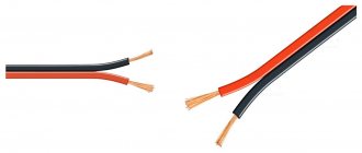
Selection of connecting wires
The cross-section is usually chosen from the following consideration: for every 10 watts of amplifier power - approximately 1 sq. mm of wire cross-sectional area. That is, with a radio power of 40 watts per channel, the cross-section of the conductor leading to the speaker must be at least 4 sq. mm.
You should think about choosing the type of speaker cable if the radio is capable of providing high-quality sound. On the Hi-end equipment market you can find many different speaker cables with unique parameters and prices.
The feasibility of installing such expensive conductors for a middle-class car radio is zero. The main thing when connecting is to ensure that the phases of the speakers and speakers are synchronized. Otherwise, the interior will be filled with cacophony instead of high-quality sound.
Headphone adapter
If you have headphones whose plug does not fit into the device, you can make an adapter.
For this you need:
- a plug that can be connected to the device;
- female connector into which headphones are connected;
- a piece of three- or four-core cable to connect the plug and connector.
Information! You can use a cable from an unnecessary mouse or keyboard.
The manufacturing procedure is as follows:
1. cut a piece 10cm long from the cable;
2. cut it on both sides to a length of 15mm;
3. strip the ends of the wires by 5mm;
4. tin the stripped ends;
5. tin the output of the plug and connector;
Recommendations for connecting a car radio
How to properly connect a car radio? Almost every car enthusiast has asked this question at least once? In this article we will tell you how to do it yourself, without turning to specialists. The car radio is powered by a battery. This is where danger awaits the inexperienced installer: out of ignorance, you can turn the plus to minus of the car radio or speakers.
Some car enthusiasts power the radio from the ignition switch or cigarette lighter - this is easier, but will affect the sound quality. The wire with which we lead the plus must be copper and stranded, about 4 mm2. in diameter. And in length it should be as short as possible.
We install an additional fuse at a distance of approximately 40 cm from the positive terminal of the battery, take the nominal value 10 - 20 A. The negative wire should be as long as possible.
These wires need to be laid at a distance from each other; we connect them to the car radio after connecting the speakers. Be careful not to let the positive wire touch the radio body or any of the speaker wires.
Now let's start explaining the correct phasing and connecting the speakers. Each of them has positive and negative terminals.
The narrow terminal is most often negative, and the wide terminal is positive. The wires from the radio are marked: those that are plain are the plus of the channel, and those with a black stripe are the minus of the channel. So, we connect the one with a single color to the wide terminal, and the one with a stripe - to the narrow one.
In low-power radios you can find 2 and 4 positive wires and one with a stripe, then you need to connect the negative wires of the speakers to the black wire of the radio and connect it to the body or minus of the battery.
-+12V BACK UP – permanent plus of the battery, which saves the settings if the radio is turned off;
Connecting wires. As a rule, when sold now, radio tape recorders are equipped with wires, but they are test wires, not installation wires; their cross-section is too small. For 40-100-watt speakers, it is necessary to use special wires with a cross-section of 1-4 mm2, copper.
The insulation should preferably be silicone, it will not burst in the cold. Measure them so that there is no excess length left and do not twist them when installing.
Plug types and applications
Depending on the diameter of the working surface, connectors are divided into:
- Micro jack 2.5 mm . They are equipped with small portable devices such as phones, players, etc.
- Mini jack 3.5 . They are installed in household appliances: computers, TVs, etc. In addition, the pinout of jack 3.5 is extremely simple.
- Big jack 6.35 . Mainly used in professional equipment: electric musical instruments, powerful acoustic amplifiers, but can be built into budget equipment, such as karaoke microphones, metal detectors.
Based on the number of outputs (pin), jacks are divided into:
- Two-pin ( TS ). They transmit an asymmetrical signal, for example, a mono signal is sent to headphones or audio is recorded using a microphone.
- Three-pin ( TRS ). Using them, you can transmit both an asymmetrical signal, with pins 2 and 3 connected by a jumper, and a symmetrical one.
- Four-pin ( TRRS ). They can immediately transmit video and audio information. Modern phones, tablets, video players, etc. are mainly equipped with four-pin connectors.
- Five-position ( TRRRS ). An uncommon connector used by Sony in the Xperia Z smartphone for the simultaneous operation of two microphones, one of which works for noise reduction. TRRS compatible.
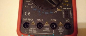
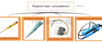
How to check the correctness of marking and wiring
Wire colors in electrical engineering are designed to speed up the identification of conductors, but relying only on colors is dangerous - they could be connected incorrectly. Therefore, before starting work, you should make sure that you have correctly identified their affiliation.
Determining the phase wire using an indicator screwdriver
We set the switch on the device so that the selected jackal is more than 220 V. Then we take two probes, hold them by the plastic handles, carefully touch the metal rod of one probe to the found phase wire, the second to the supposed zero. The screen should display 220 V or the current voltage. In fact, it may be significantly lower - this is our reality.
So, remember that when testing a phase-zero pair, the multimeter readings are always higher than when testing a phase-ground pair.
And, in conclusion, let me give you some advice: when laying wiring and connecting wires, always connect conductors of the same color, do not confuse them. This can lead to disastrous results - at best, equipment failure, but there may also be injuries and fires.
Where is the plus on the radio and where is the minus – AutoTop
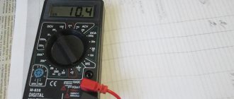
In the absence of a special designation (if it is erased, for example), the polarity can be determined using a conventional multimeter turned on in voltage measurement mode.
Expert opinion
Viktor Pavlovich Strebizh, lighting and electrical expert
Any questions ask me, I will help!
If it lights up immediately, this means that the leg connected to the battery positive is the input contact for current, and the other is the output contact. If there is something you don’t understand, write to me!
How does a headphone plug work?
If the cable is frayed, torn or the plug (pin) comes off, the device is repaired using a soldering iron with consumables and a new connector (if that is the problem).
Headphones 3.5mm
Since the 3.5 mm connectors are non-separable, for repairs you will have to buy a dismountable one, crimp the cable with a special clamp, solder the contacts according to the diagram shown below and assemble the connector.
3.5 mm plug structure
Manufacturers adhere to standards in insulation painting:
- red – left speaker – first contact or tip;
- green – right channel or ring;
- blue – speaker;
- colorless or copper-colored - mass;
- a different color – leads to the control panel (buttons).
In more expensive models, each channel may have its own mass: red-copper is the mass for the left channel, and green-copper is for the right. The microphone cable is sometimes shielded with a braided cable and varnished.
The coloring of the insulation is often violated, so relying on the coloring is wrong. To determine which pin corresponds to which channel, put on headphones and ring all combinations of wires one by one until the speaker starts to make noise. This way you can determine the mass and both channels.
The resistance between the headphones is twice as high as between ground and the audio channel.
Headphone circuit with microphone
For a headset, the schematic drawing looks different, because it is designed differently - equipped with an additional cable for transmitting sound from a microphone.
Have you noticed that in the diagrams there are different contacts for ground and microphone? Nothing strange. There are a couple of TRRS types (specifications) available with different ground and microphone contact locations. In CTIA (computer standard), the second ring (third contact) is connected to the common contact, and the sleeve is connected to the microphone, in the case of OMTP (telephone specification) it is the other way around: the 3rd contact is the speaker, the 4th is ground.
The standards are relevant only for headsets - headphones with a microphone; they have no relation to devices without one.
The standards are relevant only for headsets - headphones with a microphone; they have no relation to devices without one.
Figure No. 1
We noticed that some headsets with iPhone work adequately. The microphone fails, the volume control and track switching do not function due to the fact that most accessories are produced with the international OMPT pinout, and Apple uses the American circuit - CTIA. The problem is solved by purchasing a CTIA - OMPT adapter (see Figure No. 1) or by resoldering the 3rd and 4th contacts (they are swapped) in the headset.
The headphone pinout will allow you to correctly solder the pins when repairing the device, for example, replacing a damaged plug or cable. It depends on the number of contacts and the specification used: CTIA or OMPT.
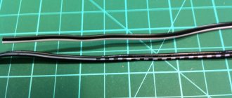
How to deal with wires in a bundle
And today it doesn’t hurt to know how to identify wires in a bundle or cores in a cable if they are the same color. Moreover, the wires may connect somewhere and arrive at the end point in a different color. This is wrong, but life happens, and connecting wires simply by color is too risky. Therefore, it is necessary to ring the circuits after installation and repair.
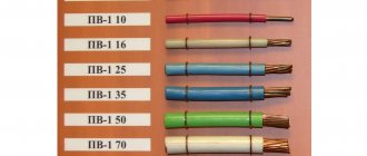
Nowadays copper wires are used almost exclusively. Aluminum is used only for overhead lines. Manufacturers paint all types of wires in any of the colors, so consumers can choose colors from the catalog.
For household consumers this is not so important. However, there should never be any confusion about what color the ground wire is. Therefore, all multi-core wires and power cords are respectively marked green or yellow-green. Any other wire is phase or neutral and must be painted in the appropriate color (zero is always blue).
Expert opinion
Viktor Pavlovich Strebizh, lighting and electrical expert
Any questions ask me, I will help!
The method for determining polarity using this method is that the cooler must be powered from the uninterruptible power supply being tested. If there is something you don’t understand, write to me!
How to find out if the connector is faulty
Insert working headphones into the jack and turn on the music. If music does not play in working headphones, your connector is broken. Also, if you hear a hissing sound when the plug moves, this means that the connector will soon completely fail.
Nowadays, the pinout of headphone wires with a microphone shown in the first picture below is mostly used everywhere, but there is also another one, which is mainly used on old phones and in phones from some manufacturers. They differ in that the microphone and ground contacts are swapped.
Telephone wires and LAN
A regular telephone line consists of two wires (subscriber pair). One of these wires is positive, the other is negative. In a 60 V line. Old devices with pulse dialing can be connected in any way, new ones may not work if the polarity is inappropriate. The socket is connected to the device via an RJ11, RJ12 or RJ25 connector.
A socket with four wires has a pair for the subscriber line: green (direct, plus) and red (return, minus) wires. Two more wires - black and yellow - are used either to supply power to some devices: black - plus, yellow - minus; or for a second subscriber line, local or office.
This socket is also used to connect a telephone handset or a headset. In this case, the green-red pair is connected to the phone (headphones), and the black-yellow pair is connected to the microphone.
The six-pin socket contains an additional pair of wires: white and blue. Telephone sockets were immediately used to connect local networks, allocating the required number of pairs for this.
Currently they use eight-pin modular connectors, mistakenly called "RJ45", for the telephone and the slow T1 network (1.544 Mbps). For modern high-speed local networks, they use the T568A or B standard, in which the connection of twisted pairs is different, and use category 5 cable.
The primary color is the first one specified in the pair. The basic principle of RJ connectors and sockets was that the pairs run sequentially from the center to the edges, but this had a bad effect on the performance of networks, since it caused mutual interference between the twisted pairs.
Universal plug - 3.5 jack pinout for connecting to headphone and smartphone jacks
Pinout of jack 3.5 is not particularly difficult; skill with a soldering iron is enough. Therefore, almost any user of headsets that require such a connector can repair a failed connector or solder a new one to the wire.
Audio jacks were invented in the 19th century for use in telephone switches and are still widely used to transmit analog audio signals.
Contact configuration
| Pin no. | PIN name | Description |
| 1. | Tip | Left |
| 2. | Ring | Right |
| 3. | Ring | Earth |
| 4. | Sleeve | Microphone |
Short description
The 3.5mm jack is a universal audio jack size for smartphones, PCs and laptops. Additionally, for hams, the 3.5mm audio jack is a useful component for projects that connect to headphone jacks. There are different types of audio connectors such as TS, TRS and TRRS used in various applications, but the most common ones that we see in everyday life are TRS and TRRS.
Self-pinout of 3.5 mm jack
To use the 3.5mm audio jack in your projects or prototypes, you must solder wires to the jack pins. Remove the above plastic shell and you will see the connector pins as shown in the images above. Now use the stranded wires to solder the pins and then cover it with the plastic casing again.
Pinout 3 5 mm jack 4 pins
Connecting a radio via an additional button
To prevent current leakage, place a button in the cut of the red wire:
With the first option, I think everything is clear: just a regular on/off button is hung in the cut of the red wire on the radio. Thus, your radio always works, but if you decide to leave the car in the parking lot for a long time, then simply turn it off. button to supply current to the radio.
The second option is when an emergency button is used instead of a regular button. You will use the second emergency button to switch the power mode of the radio:
Example of connecting a car radio:
- The radio backlight wire to the cigarette lighter backlight wire.
- Plus after ignition from the clock block (orange wire)
- A permanent plus with a battery or cigarette lighter.
- Ground "-" from the cigarette lighter
If there is a positive pulse during closing, relay P2 will operate, and the power supply circuit of relay P1 and the radio will break, the radio will turn off, and the relay will go into a de-energized state. But this scheme also has a minus - it is increased power consumption due to the additional relay P1, which will always be turned on along with a working radio.
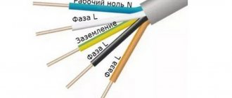
Marking of wires for alternating three-phase current
To remember which plus is red or black, they use the name of a well-known international organization - the Red Cross. This phrase suggests that red means plus.
Expert opinion
Viktor Pavlovich Strebizh, lighting and electrical expert
Any questions ask me, I will help!
When color coding is not available, it should be created at the joints using insulating tape or heat shrink tubing. If there is something you don’t understand, write to me!
How to find out if the connector is faulty
Insert working headphones into the jack and turn on the music. If music does not play in working headphones, your connector is broken. Also, if you hear a hissing sound when the plug moves, this means that the connector will soon completely fail.
Nowadays, the pinout of headphone wires with a microphone shown in the first picture below is mostly used everywhere, but there is also another one, which is mainly used on old phones and in phones from some manufacturers. They differ in that the microphone and ground contacts are swapped.
How to properly solder 3 wires (blue, green, gold) to a plug from Sony mdr-g90 headphones?
Kuzmich
In theory, blue and green are right and left, gold is common. strip the ends of the wires, insert the plug into the player or computer and touch the gold one to the base, check the blue and green ones at random, which one is right and which one is left