Posted by Andy Nehan
When it comes to voltage stabilizers LM317/337 or 78XX and 79XX immediately come to mind . All of them operate at low voltages (up to 40 Volts), have only three outputs and, as a result, simple switching circuits.
Looking ahead, I will quote from the end of this article:
“If you usually listen to amps with stabilizers like LM317s and the like, then listening to an amp with a stabilizer without feedback may come as a shock !
For me, it was comparable to the first time I tried raw fish.
Just forget about your prejudices!”
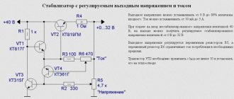
To monitor the output voltage, LM317/LM337 and similar microcircuits use feedback.
Another type of stabilizers is usually called parallel and is often said that they do not have feedback, and voltage stabilization occurs by shunting the load (the figure shows that this is not the case and feedback is also present in this type of stabilizers).
Both types of stabilizers have a number of common features. Both use an error signal amplifier . Moreover, all amplifiers have a finite gain and limited bandwidth. Ideally, you should use an error amplifier with constant gain and phase shift in the band from DC and beyond throughout the entire audio range.
The rationale behind this is that the characteristics of the error amplifier and feedback circuit determine the output impedance of the regulator such that:
1. the higher the gain, the lower the output impedance of the stabilizer
2. The output impedance usually increases monotonically with increasing frequency. It depends on the frequency response of the error amplifier and in practice the increase can begin from frequencies of 100Hz-10kHz.
The figure shows the typical output impedance of the stabilizer on the LM317 chip:
The goal of my work was to create a stabilizer with a stable output impedance over the entire audio frequency range, a high level of ripple suppression and a low noise level .
Based on these requirements, we will consider the entire path from rectification to voltage stabilization.
AC voltage rectification
Today, the requirements for the quality of network voltage are quite lenient. Add to this the huge number of consumers with switching power supplies (computers, TVs, printers, DVD players, etc.) and the nonlinear characteristics of step-down transformers. As a result, the shape of the supply voltage is far from sine. First of all, a flattening of the tops of the half-waves is observed.
The figure shows the results of measuring the voltage at the output of the Ш-shaped transformer:
Click to enlarge
I was surprised, to be honest, I expected the worst.
Note from the editor-in-chief of RadioGazeta : keep in mind that the author lives in the UK!!! In the Russian power grid the picture will not be so rosy.
I use W-shaped transformers because I like their sound better. They are not as fast as tori, but I find they provide better detail and detail in the sound.
The previous figure also shows the output voltage spectrum of the bridge rectifier .
Terrible! Even worse than at the transformer input. Now harmonics with a frequency of 2 kHz have appeared, with a level of about 60 dB relative to the 50 Hz voltage ripple.
Dear user!
We assemble a simple bipolar laboratory power supply for the laboratory of a novice radio amateur. Good afternoon, dear radio amateurs! In this lesson of the Beginner Radio Amateur School, we will begin to create a radio amateur laboratory. For more or less high-quality execution of the intended design, a radio amateur needs a minimum set of instruments to configure and test the functionality of the circuit he is assembling. In addition to the multimeter tester, you must have: a laboratory power supply to check the functionality and configure the circuit, and so that for each circuit, before setting it up, do not assemble a separate power source; generator of rectangular, sawtooth, sinusoidal pulses - for setting up the circuit; frequency meter for measuring the frequency characteristics of the assembled circuit or its settings. These are the main devices. We'll start with a laboratory power supply.
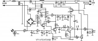
A bipolar voltage stabilizer based on a unipolar DA1 microcircuit with a stabilization voltage of 5 V is made according to the circuit in Fig. 12th century
Clean entry
I wanted to get a clean input voltage as much as possible by clearing it of harmonics and eliminating all transients. The fact is that all stabilizers have some capacity between the input and output. Plus , interference can penetrate the output of the stabilizer through feedback circuits or a common wire. Therefore, at the input of the stabilizer we need to have the cleanest signal possible.
Sounds a little utopian? How to get a “clean” voltage at the stabilizer input? RC or LC filters can significantly reduce harmonics in the rectified voltage. What signal is considered clean enough?
Quite popular in tube amplifiers are rectifiers based on kenotrons , which, due to their design features, are asymmetrical, but nothing... these amplifiers sound!