Powerful power supply.
Sergei Nikitin.‘>
I once worked in a trolleybus depot repairing electrical equipment. Our workshop was located on the second floor of a building in the park. We repaired and tested trolleybus electrical and radio equipment. And so, in order to check the serviceability of powerful electrical equipment and trolleybus converters, the men carried heavy batteries from trolleybuses, and even to the second floor. Laziness, as they say, is the engine of progress, I can’t handle such things, and the men are pretty tired, and thanks to this, the idea was born to find a replacement for these activities and make a fairly powerful power supply with which it would be possible to check the performance of any trolleybus electrical equipment. I had a powerful power supply in the garage, and using the same scheme, I decided to assemble a similar device for the needs of the trolleybus fleet, which would be of help to me, and to the joy of the men.
This circuit is a powerful power supply, where thyristors are used as control elements. The entire power of this power supply is limited only by the power transformer and thyristors. If you install a more powerful transformer and thyristors, then the output current of this power supply will increase accordingly.
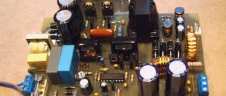
The power supply was assembled mainly from parts of decommissioned and disassembled office equipment and from what was found there. And there, in the trash, I found a ready-made transformer from an uninterruptible power supply UPS-1200, which produces 2x30 Volts, thyristors VS1 - VS2 T50 for 50A, you can use any ones with a current of at least 40A instead, and if the load current is planned to be less, then of course you can install thyristors with less current. Choke L1 was also found in radio junk from an unknown device, the magnetic circuit looked like from TSSh-160 (TSSh-170) and the window was completely filled with a winding, a wire with a diameter of 3 mm with a gap of 1.5-2.0 mm , quite a powerful looking throttle. If you don’t find a ready-made throttle, you can make it yourself. The core can be taken from any power transformer with a power of 100-120 W, preferably a W-shape (SH) and the winding can be wound with a wire with a diameter of 2.0-3.0 mm (a set of wires), or even both P and PL cores are suitable . You can wind a winding on them on one frame until the window is filled, or divide it into two frames and then connect the halves in series (beginning with beginning or end with end) and assemble a core with a similar gap. Transformer TV2 was taken from some kind of transistor radio receiver; this is a matching transformer. You can use any one of a similar purpose, or wind it yourself on a small core, according to the data available in reference books on transistor radios, Radio magazines or on the Internet. The minimum output voltage of the power supply was about 1.5V, the maximum under full load was 30 Volts. The power supply keeps it quite stable.
The power supply, as I said, works very stably. Transistor VT2 forms a “saw” for PWM operation, synchronized with the network through transistor VT1. It is advisable to select capacitor C7 according to the linear shape of the “saw” on it. I installed filter capacitors C11-C12 at 2200 uF 50 volts; the diagram shows their minimum capacity. At K140UD7, pulses are generated that already control the thyristors through a composite (Darlington) transistor VT3. Instead of K140UD7, you can install K140UD6, K140UD8 and almost any others that are suitable for the supply voltage and a load resistance of at least 2 kOhm. These microcircuits are not critical to the supply voltage, so as KS515 you can use any other zener diodes with a stabilization voltage from 12V to 15V (D814G, D814D, KS512) or imported ones. Transistors VT1-VT2 can be used of any corresponding structure, and instead of VT3 you can also use any Darlington of the corresponding structure, for example from old matrix printers, they are used there to control stepper motors.
You can try using a MOSFET with an N-channel instead of VT3, then any operational amplifier will do, the only thing you need is to reduce the capacitance C13 to 10nF, increase the resistor R12 to 100kOhm. Capacitor C8 ensures stable operation of thyristors at low load currents and smooth voltage supply after the power supply is connected to the network. I didn’t make a printed circuit board; I did all the mounting on a small board, to which I glued electrolytic capacitors and mainly used their terminals as mounting points.
This control circuit has also been used in car battery chargers. The output voltage of the secondary of the power transformer, then 2x15-18 volts will be enough, with the permissible current with which you plan to charge the batteries. Thyristors for the charger will be sufficient for 10-25 amperes and inductor L1 can be excluded from the circuit. For such purposes, I try to use wire resistors (R10) as a regulating resistor; they are more reliable, especially for the garage or where there are differences in temperature and humidity. The thyristors are mounted on an aluminum plate, which is used as a thyristor mount, as a contact, and as a heat sink.
Yes, if you need to wind up a matching transformer and don’t find it ready, then the thyristor control circuit can be made using this option.
In this case, there is no need to install a transformer. I took the most popular optocouplers from the 817 series, which are found in computer power supplies, and they controlled T122-25 thyristors. This scheme also worked quite well. Yes, I have not tested this circuit for operability with powerful thyristors and with old Soviet-made thyristors. I don't know how she will work with them. There, simply with a small output voltage, you need to keep the holding current and the control current too, otherwise periods are skipped chaotically and the transformer begins to twitch and click. In order for the thyristors to be normally open in this case (the required holding current flows through them), you can place a load resistor of appropriate power before the ammeter (in parallel with capacitors C11-C12), which would provide the required holding current for the thyristors at a minimum output voltage, and which would withstood the maximum output voltage. I didn’t do any protection in this power supply because I didn’t want to do a complicated one, and a simple one usually doesn’t have time to work. I just installed Sovdepov’s thyristors, which are much more reliable than transistors, and when you come across free thyristors, you can install more powerful ones with a reserve. Good luck in your creativity and all the best!
Brief classification of power sources for arc welding
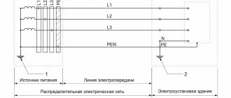
As shown in the diagram below, arc welding power sources can be classified according to various criteria.
According to the first criterion, power supplies are classified according to the method of energy production: whether it is converted from the power supply network (as is the case with transformers, rectifiers and electronic power supplies) or generated by the power supplies themselves (as is the case with generators).
According to the second criterion, power sources are classified according to the method of converting electrical energy:
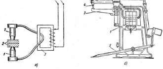
- by using transformers that convert the relatively high voltage of the power network into a lower voltage for welding with alternating current; — by using welding rectifiers, consisting of a transformer (to reduce the voltage of the power network) and a rectification unit to convert alternating current into direct current; — by using electronic power sources (for example, welding inverters); - by using welding converters consisting of a welding generator, the rotation of the rotor of which is provided by an electric motor; — by using welding units consisting of a welding generator, the rotation of the rotor of which is ensured by an internal combustion engine (strictly speaking, the unit converts not electrical energy, but mechanical into electrical energy).
The third classification feature is the method of obtaining energy: power sources can be dependent (all except units, since they receive energy from a stationary electrical network) and autonomous (units, since their generator is connected to an internal combustion engine).
According to the fourth criterion, power sources are classified in accordance with the method of regulating welding parameters. In transformers and rectifiers, this can be done using moving coils, moving magnetic shunts, sectioning the turns of the secondary winding and other methods.
The fifth classification feature is the type of welding current that is provided by power sources: alternating (AC), direct (DC) or both, both AC and DC (combined power sources).
According to the sixth classification criterion, power supplies are classified in accordance with the form of the external (static) current-voltage characteristic (V-VAC). The external current-voltage characteristic of the power source is the dependence of the average voltage at the source terminals on the current strength in the welding circuit. It can be either falling (CC - constant current) or hard (CV - constant voltage). In both cases, these definitions are not entirely accurate and are conditional, accepted in welding practice. For more information about the current-voltage characteristic, see Volt-ampere characteristic of the arc
Uхх – open circuit voltage
Power supplies with a falling I-V characteristic are characterized by the following basic properties:
— have a high open-circuit voltage (≈ 2 ... 2.5 times higher than the operating arc voltage); — the voltage at the power source terminals drops significantly as the welding current increases; — have a limited short-circuit current (not higher than 1.1 ... 1.3 of the rated welding current).
Power supplies with rigid V-voltage characteristics are characterized by the following basic properties:
— the no-load voltage is only slightly higher than the operating arc voltage; — the voltage at the power source terminals drops slightly as the welding current increases; - short circuit current can reach very high values (2 ... 3 times higher than the rated welding current).
The shape of the external current-voltage characteristic of the power source is determined experimentally by measuring the voltage at the external terminals of the power source (Un) and the current in the circuit (I) with a smooth or stepwise change in the load resistance (Rн) and at constant values of the open circuit voltage, active and inductive components of the internal resistance power supply. As the load resistance decreases, the current in the circuit increases, the voltage drop inside the power source increases and, accordingly, the voltage at the external terminals of the power source (Un) decreases. The rate of voltage decrease Un (in other words, the slope of the external current-voltage characteristic) is determined by the value of the internal resistance of the power source. The higher the internal resistance of the power supply, the steeper the external current-voltage characteristic of the power supply becomes.
The static I-V characteristic should not be confused with the dynamic characteristic of the power source, which characterizes the rate of change of instantaneous current values in the welding circuit.
The table below presents data for selecting the type of current and the shape of the I-V characteristics of the power source, depending on the arc welding method.
| Welding method | D.C | Alternating current | |
| Falling | Tough | Falling | |
| Manual arc welding (MMA) | Yes | No | Yes |
| Tungsten inert gas arc welding (TIG) | Yes | No | Yes |
| Mechanized arc welding with a consumable electrode in shielding gas (MIG/MAG) | No | Yes | No |
Welding power sources are also designed for different operating modes, which are assessed by the relative operating duration (OL; sometimes designated as LO - Load Period):
PR = (working time (welding) / time of the entire cycle (welding and pauses) = 10 min) * 100%
The duration of the entire work cycle (welding and pause) for sources is assumed to be 10 minutes. For example, if PR = 20%, then this means that after 2 minutes of welding at rated current, it is necessary for the source to cool for at least 8 minutes. Otherwise, it may overheat and fail.
How to test a thyristor: 3 accessible methods for beginners
I will show the principle of this technology using the example of the KU202N power thyristor for one simple reason: it was at hand when writing the article, and I managed to distribute more and more powerful models to friends for their homemade products...
I will show methods of electrical checks using his example. To do this, I am publishing important characteristics that must be taken into account when working. They are divided into two groups:
- limit;
- nominal.
The parameters of the first category relate to the pulse mode used for a short time. We are not interested in them: only nominal indicators can create long-term operation.
Please note:
- The maximum permissible voltage is 400 V;
- Direct current in open and closed state - 10 A;
- Holding current - 200 mA;
- Unlocking constant current - 100 mA.
This data for other semiconductor devices can be found in technical reference books and on numerous Internet sites.
The very first testing method: with a dial tester or digital multimeter
Assessing the serviceability of KU202N using the Ts4324 device in 3 steps
I still have this rare measuring instrument from an old electrician in working order. It has been preserved thanks to the quality mark and constant care during measurements.
Step #1. Setting the mode and measuring the closed state of the transition
I set the resistance measurement mode with the central switch and the “kilo-ohm” limit with the button. I connect the positive terminal of the circuit to the anode, and connect the negative terminal to the cathode.
For clarity, I marked them in the photo with bright red “+” and “-” directly on the insulation of the crocodiles.
The measuring needle shows a very high resistance. The same will happen if the polarity of the terminals is reversed. You can check.
Step #2. Thyristor opening
By touching my hand, I connect the output of the control electrode to the body (anode) of the semiconductor.
The arrow sharply deviates towards the beginning of the scale in the direction of lower resistance. A reading of about 0.15 k indicates the opening of the np junction.
Step #3. Checking the open state when removing the control signal
I remove the output wire from the semiconductor body and observe the arrow reading.
It has not changed: the transition has retained its open position. He's fine.
Checking the status of KU202N with a digital multimeter
There are no fundamental differences in the analysis of thyristor devices. The technology is the same. I show it with photographs using the example of my Mestek MT-102 pocket multimeter.
For the first step, I switch it to semiconductor testing mode and connect the device with alligator clips.
The display shows that the transition is closed: the resistance is high.
Then I bridge the output of the control electrode to the anode. The semiconductor has opened.
When the jumper was broken, the readings on the display did not change.
A test method accessible to everyone using current from a battery and a regular light bulb.
This technique is popular, but it requires first taking into account the technical characteristics of the device under test and the output values from the load created by the light bulb.
For power transistors this is not critical, but in low-power products the structure of electronic components can be damaged by excessive current.
I will demonstrate the technique using the example of the design of the most affordable Chinese LED flashlight and an ordinary light bulb. There are no fundamental differences when using one AA or AAA battery.
Just in case, I measured the light bulb current with a multimeter.
The result was 183 milliamps, which is quite normal for our case.
Now I use this battery pack to test. I feed it plus to the anode, and minus to the cathode of the semiconductor being tested through a light bulb.
There is no glow. This means that the resistance of the circuit being tested is high, all transitions are closed.
I close the control electrode to the body of the device - the anode.
The light comes on: the device has opened.
The thyristor can be put into operation by applying a positive voltage from a AA battery to its anode, and the negative must first be connected to the control electrode.
This is what the reference books recommend, but I prefer the first method. It's simpler.
Now I open the created connection. The light does not stop glowing: the current continues to flow through the anode-cathode circuit.
The semiconductor remains in the open position and is in good condition.
How can you check a thyristor on an electronic board without desoldering it from the circuit: advice from experienced
Work, as always, must be performed with stress removed. This is done not only for safety purposes, but also for the reliability of the result.
The next step is to remove the control electrode from the board circuit. You can disconnect its contact with a soldering iron or cut the track with a knife.
I will conduct an experiment on the same KU202N without a board. To check you will need 2 separate devices:
- ohmmeter;
- DC millivoltmeter.
They can be replaced with two multimeters or testers, which I show with the following photographs. I switch my Ts4324 tester to the DC voltage measurement mode at the limit = 1.2V. I connect it to the anode and cathode.
I set the Mestek MT-102 to ohmmeter mode and use crocodiles to place it on the terminals of the semiconductor so that the plus goes to the control electrode and the minus to the anode.
The tester's needle deviated to the right, showing a value less than a volt. Based on this measurement, one can judge the serviceability of the semiconductor junction.
Any of the three testing methods is based on the operating principles of thyristors. It takes into account the flow of currents through semiconductor junctions. When performing them, it is important to evaluate four sequential stages: Normal closed state until a command is received. Opening on command. Holding open when the control signal is turned off. Closing when power is lost.
For a more visual representation of these processes, I specially recorded a video. Watch it here.
However, I only considered the KU202N, as a fairly common model, although it has already been discontinued. It is difficult to show all the others in one article. And there are a lot of them.