The problem is that the voltage in the electrical network changes depending on its load, and for the correct operation of most electricity consumers it is necessary to find the supply voltage in a certain range so that it does not exceed or fall below a certain permissible limit.
Therefore, we need some ways of regulating, regulating, regulating the mains voltage. One of the best ways is to change the transformation ratio as needed by decreasing or increasing the number of turns of the primary or secondary winding of the transformer according to the well-known formula: U1 / U2 = N1 / N2.
To adjust the voltage on the secondary windings of transformers in order to maintain the correct voltage for consumers, some transformers have the ability to change the turns ratio, that is, adjust the transformation ratio in one direction or another.
The vast majority of modern power transformers are equipped with special devices that allow you to adjust the transformation ratio, that is, add or subtract turns in the windings.
This adjustment can be made either directly under load, or only when the transformer is grounded and completely de-energized. Depending on the importance of the object and the frequency with which these adjustments are necessary, there are more or less complex systems for switching turns in the windings: those that perform switching without load - "switching without excitation" or with load switching. — “settlement under load.” In both cases, the transformer windings have branches between which switching occurs.
Switching without excitation
Non-excited switching occurs from season to season, this is a planned seasonal shift change when the transformer is taken out of service, which obviously will not work often. The transformation coefficient has changed, more or less within 5%.
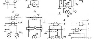
On high-power transformers, switching is performed using four sockets, on low-power transformers - only using two. This type of switching is associated with a power outage of consumers and is therefore performed quite rarely.
Often sockets are made on the higher voltage side, where there are more turns and the adjustment is more accurate, besides, the current is less and the switch is more compact. The change in magnetic flux at the moment of such switching of turns on a step-down transformer is very small.
If it is necessary to increase the voltage on the lower voltage side of the step-down transformer, the turns on the primary winding are reduced; if it is necessary to decrease them, they are added. If the adjustment is made from the load side, then increase the voltage of the turns of the secondary winding to increase it, and decrease it to decrease it. A switch used on a de-energized transformer is colloquially called an anzapfa.
The contact point, despite the fact that it is made of a spring, undergoes slow oxidation over time, which leads to an increase in resistance and overheating. To prevent the occurrence of this harmful cumulative effect, so that the gas protection does not work due to oil decomposition under the influence of excessive heat, the switch is regularly serviced - twice a year, the correct setting of the transformation ratio is checked, when switching the anapf to all positions, in order to remove the oxide film before final installation the required degree of transformation.
Also measure the DC resistance of the windings to ensure the quality of the contact. This procedure is also carried out for transformers that have not been used for a long time before being used.
Load control
Online switching is performed automatically or manually, directly under load, where the voltage varies significantly at different times of the day. High and low power transformers, depending on the voltage, have on-load tap-changers of different ranges - from 10 to 16% with a step of 1.5% on the higher voltage side - where the current is less.
Here, of course, there are some difficulties: on a powerful transformer it is simply impossible to break the circuit, since in this case an arc will occur and the transformer will simply fail; short-circuit the turns to each other for a short time; current limiting devices are required.
Current-limiting reactors in switching systems under load
Current limiting load control allows you to create a system with two contactors and double winding reactance.
The two windings of the reactor are connected through a contactor, closed in normal operation of the transformer, next to the same contact at the winding terminal. The operating current flows through the transformer winding, then in parallel through two contactors and through two parts of the reactor.
During the switching process, one of the contactors is switched to the other terminal of the transformer winding (let's call it “terminal 2”), while part of the transformer winding is short-circuited, and the operating current is limited by the reactor. Then the second contact of the reactor is switched to “pin 2”.
The setup process is complete. A switch with a reactor has small losses at the midpoint, since the load current overlaps the convection current of the two switches, and the reactor can always be in the circuit.
Current limiting resistors in switching systems under load
An alternative to reactance is a spring contactor in which 4 quick switches are switched in series using intermediate positions where the current is limited by resistors. In the operating position, current flows through the bypass contact K4.
If it is necessary to switch the circuit from position II to position III (in this case with a smaller number of turns), the selector is moved from pin I to pin III, then resistor R2 is connected in parallel to the closed contactor K4 through contactor K3, then contactor K4 is opened and now the current in the circuit is limited only resistor R2.
The next step is to close contactor K2 and some current also flows through resistor R1. Contactor K3 opens, isolating resistor R2, branch contact K1 closes. The transition is complete.
Although it is difficult to interrupt the reactive current of a switch using a reactor and is therefore more commonly used on the low voltage side with high currents, a fast acting switch with resistors has been successfully used on the high voltage side with relatively low currents.
Under normal conditions, a car battery is charged while driving. But if the car sits in the garage for a long time, the battery will drain.
To charge it, you will need a charger with adjustable charging current. One of the options for these devices is a charger with adjustment to the primary winding of the transformer.
Features of regulators for primary transformers
The charging current of the battery is 10% of its capacity. This means that a 60 Ah battery is charged with a current not exceeding 6 A. The charging voltage when the vehicle is running is 14.5 V. Taking into account the required range, the charger should output 10 A at 16 V.
The voltage reserve is necessary to regulate and limit the charging current.
It is produced differently in different device models:
- Additional resistors. They light up after the diode bridge. The simplest design, but the largest.
- Transistor. High control accuracy, but the most complex circuit that requires good cooling of power transistors.
- Thyristor control. Simple diagrams. The adjustment is carried out by a thyristor switch in the primary winding circuit or by thyristors installed instead of diodes in the rectifier bridge.
Simple regulator circuit
The circuit of a simple regulator directly includes a gate-type thyristor and a controller for controlling the limit voltage. Transistors are used to stabilize the current at the beginning of the circuit. Capacitors must be used in front of the controller. Some use combined analogues, but this is a controversial issue. In this case, the capacitance of the capacitors is estimated based on the power of the transformer. If we talk about negative polarity, then inductors are installed only with the primary winding. The connection to the microcontroller in the circuit can occur through an amplifier.
Diagram and purpose of a thyristor voltage regulator for a transformer
The current flowing through the battery during charging is determined by the internal resistance of the battery, its emf and the voltage at the charger output. To change it, among other methods, you can adjust the voltage on the primary winding. It is most convenient to use a thyristor regulator.
Battery charging models
Chargers are divided into three groups:
- Launchers. Designed to start an engine with a discharged battery. It is not recommended to use batteries for recharging: insufficient voltage and lack of adjustments.
- Charger. Designed for charging batteries. They have manual or automatic adjustment.
- Starter charger. They can perform both functions.
Is it possible to make a regulator yourself?
You can make a thyristor voltage regulator with your own hands, following standard circuits. If we consider high-voltage modifications, then it is best to use sealed type resistors. They can withstand maximum resistance at 6 ohms. As a rule, vacuum analogs are more stable in operation, but their active parameters are lower. In this case, it is better not to consider general-purpose resistors at all. On average, they can withstand a nominal resistance of only 2 ohms. In this regard, the regulator will have serious problems with current conversion.
For high power dissipation, class PP201 capacitors are used. They are distinguished by good accuracy, high-resistance wire is ideal for them. Lastly, a microcontroller with a circuit is selected. Low-frequency elements are not considered in this case. Single-channel modulators should only be used in conjunction with amplifiers. They are installed at the first and also at the second resistors.
Operating principle of a thyristor regulator
A thyristor has two states: open, in which electric current passes, and closed. This element opens when current flows through the gate electrode and remains open when current flows through the thyristor. The alternating voltage in the network is sinusoidal. A thyristor connected to the load circuit opens at a certain moment of the half-wave. This is called the "opening angle". As a result, current does not always pass through the electrical device, but only after the element has passed into the open state. This changes the RMS voltage across the load.
Important! A voltmeter measures the RMS value. For reliable operation, the permissible voltage of the thyristor must correspond to the maximum voltage, which is 1.4 times higher. For a home network this is 308V.
Properties of the regulator with thyristor KU 104a
The specified thyristor voltage regulators work with transformers whose power exceeds 400 V. The layout of their main elements may differ. In this case, the limiting frequency should be at 60 Hz. All this ultimately puts a huge load on the transistors. Here they are used closed type.
Due to this, the performance of such devices increases significantly. At the output, the operating voltage is on average 250 V. It is not advisable to use ceramic capacitors in this case. Also, a big question among experts is the use of trimming mechanisms to regulate the current level.
Types and technical characteristics of thyristor regulator
Due to the fact that the thyristor passes voltage of only one polarity through itself, it cannot be used to control a transformer without additional elements:
- Connect the thyristor to a diode bridge of 4 diodes at the “+” and “-” terminals. Production "
“They are connected to an open circuit instead of or in series with a switch. The diode bridge rectifies the voltage and only one polarity is supplied to the thyristor.
- Use two thyristors connected back-to-back in parallel, and connect the control outputs through a variable resistor. Each element opens with its own polarity, and both together control the voltage across the load.
- Variable resistance between the anode and the control electrode. During the first half of the half-wave, the control voltage and current also increase when they reach a certain value, depending on the brand of the element. The disadvantage of this circuit is the limited adjustment range of 110-220V, but this is enough to control the charger transformer.
- Control of the pulses that a separate circuit supplies to the control electrode at a given moment in the half-wave of a sine wave. The permissible current and voltage of the thyristor regulator mainly depend on the installed thyristors. The most common thyristors are the KU 202 series, but in some cases the use of other elements is allowed:
- KU202N - 400V, 30A. Fixed with M6 thread. When adjusting the primary winding, the current of which is less than 1A, they are used without radiators.
- KU 201l - 300V, 30A, fastening - M6 thread. Can be used in the primary winding.
- KU 201a - 25V, 30A, fastening - M6 thread. Can only be used with adjustable radiators after the transformer.
- KU 101g - 80V, 1A. Looks like a transistor. Chargers are not used in power circuits, only in control circuits.
- KU104a - 6V, 3A. They are also not used in power circuits.
The thyristor opens when the current exceeds a certain value, and there are two ways to control the opening angle:
Battery charging models
The thyristor battery charging voltage regulator (the diagram is shown below) is distinguished by its compactness. It can withstand a maximum resistance in the circuit of 3 ohms. In this case, the current load can only be 4 A. All this indicates the weak characteristics of such regulators. Capacitors in the system are often used of a combined type.
In many cases their capacitance does not exceed 60 pF. However, much in this situation depends on their series. Transistors in regulators use low-power ones. This is necessary so that the dispersion index is not so large. Ballistic transistors are not suitable in this case. This is due to the fact that they can only pass current in one direction. As a result, the voltage at the input and output will be very different.
What is a triac
The thyristor has a drawback that complicates its use in an alternating current network: only a half-wave passes through itself, and the output produces a constant ripple instead of an alternating voltage. Therefore, these devices are used in pairs or together with a diode bridge. The triac is free of this drawback.
A triac is similar to a thyristor. Like a thyristor, it is opened by a pulse of current flowing through the control electrode, but this device passes both half-waves through itself and is capable of operating in an alternating current network.
Schematic diagram of a triac current regulator for active and inductive loads. The design of a triac regulator is similar to a thyristor regulator. The difference is that the triac controls both polarities, and therefore there is no need to use a diode bridge or back-to-back connection of elements.
In addition, the polarity of the control voltage does not matter for the triac, which simplifies the pulse control circuit.
Advice! To adjust the triac, you can use a dimmer from an incandescent lamp. To do this, it is connected between the anode and the control electrode of the power triac.
KU 201l regulator diagram
The KU 201l thyristor voltage regulator includes bipolar transistors, as well as a multichannel microcontroller. Capacitors in the system are used only of the combined type. Electrolytic semiconductors are quite rare in regulators. Ultimately, this greatly affects the conductivity of the cathode.
Solid-state resistors are only needed to stabilize the current at the beginning of the circuit. Resistors with dielectrics can be used in conjunction with rectifier bridges. In general, these thyristors can boast high accuracy. However, they are quite sensitive and keep the operating temperature low. Due to this, the failure rate can be fatal.
Other simple options for adjusting the voltage in the primary
In addition to thyristor and triac regulators, there are other ways to control the charging current in the primary winding of a transformer:
- By switching the terminals of the primary winding. The disadvantage is that these conclusions have to be made when winding the coils.
- Connecting the charger after LATRA (laboratory autotransformer). Its power must be at least 160W.
- A variable resistor connected in series to a transformer. Its parameters are about 50-100 Ohms, with a power of 50 W and depend on the specific charger.
Despite the advent of modern chargers, many car owners have devices with conventional transformers, and setting up the device through the primary winding allows you to do without powerful thyristors or additional resistors.
. The proposed universal design is designed for charging 12 and 6 volt acid batteries and is capable of providing a charge current of up to 5-6 A. The current adjustment is smooth. Unlike conventional circuits, in this design the control element (thyristor VS1) is included in the primary winding circuit, which significantly reduced the power dissipated on it and made it possible to do without installing a thyristor on the radiator. The control circuit installed on comparator PA1 is also quite inexpensive, since it does not have a powerful shunt, which is usually included in the secondary circuit. Let's take a look at the circuit diagram of the charger.
Since the control element is a thyristor, which cannot operate with alternating current, it had to be included in the diagonal of the bridge assembled on diodes VD1 - VD4. The current through the primary winding (and therefore the charging current) is regulated by changing the opening angle of the thyristor - this is controlled by a control unit assembled on a unijunction transistor VT1.
When the resistance of variable resistor R6 changes, the charging time of capacitor C1 also changes. The longer the capacitor takes to charge, the later the transistor and therefore the thyristor opens after the start of the mains voltage period. Thus, the current through the primary winding of transformer T1 can be smoothly adjusted from 0 to almost 100%. In this case, the voltage on the secondary winding of the transformer will vary from 0 to 18-20 V, which will cause a change in the battery charging current.
The charging current is controlled indirectly by measuring the current through the primary winding using a comparator PA1 connected through a ballast resistor R2 and deflected by a two-watt resistor R1. Lamp HL1 is a signal lamp.
In the project, in addition to those indicated in the diagram, diodes D231 - D234, D245, D247 with any letter index, KD202 with the letters K, M, R can be used. They cannot be installed on heating radiators. Thyristors KU201K, L, KU202K, L, M, N will work like VS1. The thyristor also does not need a radiator. In the secondary circuit (instead of VD5 - VD8), in addition to those indicated in the diagram, D231 - D233 will work without a letter index or with the letter A. They must be installed on radiators with an area of at least 30 cm2 each (if the diodes are germanium - D305), or a square 100 cm, if silicon.
Capacitor C1 must have a minimum temperature coefficient of capacitance, for example, type K73-17, K73-24. Otherwise, when the device heats up, the charging current “turns off”. Like T1, any network transformer with a power of at least 150 W is suitable, capable of supplying a voltage of 18-20 V from the secondary winding with a current of up to 6-7 A. It is very convenient for these purposes to use standard TN or TAN transformers, the characteristics of which can be found in our handbook on transformers. Any microammeter with a total deviation current of 100 μA can be used as a PA1 meter.
Setting up the device comes down to selecting the resistance value R2 to calibrate the PA1 device while simultaneously monitoring the charging current. Perhaps the only drawback of such a charger is the presence of mains voltage on the control circuit, therefore, for safety reasons, it is necessary to place a handle made of insulating material on resistor R6.
A. Evseev “Electronic devices for the home”, 1994
Attention! The design has a transformerless power supply, so during operation, life-threatening voltage is present on all its elements. Before any welding or circuit modification, be sure to unplug the structure!
On-load tap-changer tank jet protection
110 kV power transformers usually have a built-in on-load voltage regulation device (OLTC).
The on-load tap-changer is located in a separate compartment of the transformer tank, isolated from the main tank with windings. a separate protective device is provided for this device .
All damage inside the on-load tap-changer tank is accompanied by the release of transformer oil into the conservator, therefore, in the event of an oil flow, the jet protection is instantly activated, automatically disconnecting the power transformer from the electrical network.
Repair of switching devices (transformer on-load tap-changer)
When repairing switching devices without excitation ( PVB ), carefully inspect all contact connections of the switch and taps; determine the tightness of the contacts by checking the gap between the lamellas with a feeler gauge; measure the transient electrical resistance.
Particular attention is paid to the condition of the contact surface.
If there are burns or melting, the device is replaced (depending on the nature or extent of damage, the device is sometimes restored).
To remove deposits formed when working in oil, the contact part of the switch is thoroughly wiped with a technical cloth soaked in acetone or gasoline. The rest of the device is washed with clean transformer oil.
When repairing load control switching devices (OLTC), in addition to general work on cleaning, wiping and rinsing the external and internal surfaces of parts and parts of the device, the contact surfaces of the stage selector, contactors and the electrical part of the drive mechanism are checked. The burnt contacts of the selector, the main contacts of the contactor and the drive are carefully cleaned and checked for tightness, after which the cause of the burn is determined and eliminated.
Failure of the switch drive can be caused by moisture ingress due to poor sealing of the cabinet door, as well as due to significant play in the connecting shafts. Identified defects are eliminated. Remove sediment remaining after draining the oil from the bottom of the contactor tank, and also perform other work in accordance with the operating instructions for the on-load tap-changer.
On-load tap-changer protection
To ensure normal operation of the device, gas protection is used. An additional container (expander) is made, connected to the main oil medium of the transformer by a special channel in which a relay and a signal element are installed.
If gas formation is slight, the signal element indicates a decrease in the oil level. In the event of a blowout, the expanded oil is forced into the conservator. If the surge intensity reaches the set value, the relay is activated, turning off the transformer. In this way, the on-load tap-changer contactors are protected from destruction.
Advantages and disadvantages of regulation using on-load tap-changers
The advantages of regulation without disconnecting the load are the ability to maintain network parameters at the output of the transformer at a given level when the characteristics of the supplied voltage change.
This device also allows you to adjust the parameters, taking into account the required value.
The specified functions are achieved without shutting down the unit.
The disadvantages are associated with the need to complicate the design of the transformer due to the use of additional elements.
At the same time, the reliability of the unit’s operation decreases, its weight and overall dimensions increase.
Video: Voltage regulation of power transformers
Video: Transformer with on-load tap-changer, operation diagram
On-load tap-changer of power transformer, principle of operation
Purpose
Voltage booster transformers (linear regulators) are used to regulate voltage in individual lines or in a group of lines. They are used, for example, to improve the operation of networks that use transformers without load regulation. Linear regulators allow you to create an additional EMF in the network, which adds up to the network voltage vector and changes it. In Fig. Figure 1 shows a schematic representation of a boost transformer (linear regulator).
Figure 1 – Schematic representation of a linear regulator
Installing a voltage booster transformer allows you to equalize the voltage in the electrical network; eliminate voltage asymmetry in a certain section of the circuit; reduce the dangerous consequences of burning out the neutral conductor
Scheme and design
A more detailed diagram of a linear regulator, also illustrating the principle of switching contacts, is presented in Fig. 3. It shows the control transformer 1 and the series transformer 2. The primary winding 3 of the control transformer is the supply winding. It can be connected to both phase A - 0 and line voltage (A - B, A - C). The secondary winding 4 of the control transformer has the same switching device 5 as the transformer with on-load tap-changer.
One end of the primary winding 6 of the series transformer is connected to the midpoint of the secondary winding of the control transformer. The other is to the switching device. The secondary winding 7 of the series transformer is connected in series with the winding of the power transformer. The additional EMF in winding 7 adds up to the EMF of the power transformer and changes it.
Figure 3 – Operating principle of a booster transformer
In Fig. Figure 4 shows a three-phase circuit for connecting a booster transformer to the network.
Figure 4 – Scheme for connecting a voltage booster transformer to the network
Linear regulators operate according to an autotransformer circuit and are an oil-filled design that has six linear terminals for connecting the regulator to a line cut at any point. The connection diagram of the linear regulator is shown in Fig. 5.
- High voltage field winding
- Control circuit power winding
- Voltage booster winding
- Moving switch contact
- Auxiliary switch contact with active current-limiting resistance
- Fixed contacts
Figure 5 – Linear regulator connection diagram