Isolation transformers are those with the same voltage or current characteristics at the output and output. Such devices have the same number of turns on the primary and secondary coils. As a result, the transformation coefficient is equal to unity. The use of such units increases safety, since there are no electrical connections in the secondary circuits with a voltage source or ground.
The separation of the input and output windings is ensured by reinforced double insulation. An additional measure is to place the coils on physically different cores.
The secondary winding is made without grounding the zero contact, so accidental touching it will not cause an electric shock unless a person simultaneously touches a metal pipe, does not stand in a damp place, or the danger of electric current passing through the body arises in another way.
Principle of operation
The device operates on a principle similar to a conventional transformer: when current is supplied to the primary coil, a magnetic flux is induced in it, followed by its formation in the secondary winding, which causes the transmission of electric current. Since the characteristics of the coils are identical, the electric current parameters of the primary and secondary windings will be the same.
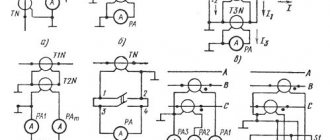
Isolation transformer circuit
What is the protective effect of an isolation transformer, the principle of operation
The design and operating principle of an isolation transformer are no fundamentally different from the operating principle of a transformer; The device carries out the same transformation of electricity.
On the common magnetic core of the device there are two windings made of the same insulated wire with the same winding characteristics. The electrical power of a sinusoidal harmonic is passed through the primary winding and, based on the laws of electromagnetic induction, is converted into the secondary. The voltage vector in the output circuits of the secondary winding completely repeats the parameters of the primary. Of course, if we take into account the accuracy classes of metrological measurements, then certain errors in magnitude and angles exist. However, this is pure theory; During operation, errors are not taken into account.
The main task of an isolating transformer is to increase electrical safety due to the fact that its secondary circuits do not have an electrical connection with the ground, and therefore with the grounded neutral of the transformer substation - the voltage source.
how does a safety transformer work?
In this case, the occurrence of an electrical breakdown on the housing does not cause overcurrent, and the device itself remains in working condition. If a person accidentally touches a part of a device that is emergency energized, the leakage current will not exceed a life-threatening threshold and no tragedy will occur.
Based on its purpose, the isolation transformer is used in all spaces included in the high-risk group. First of all, it is used for installation in swimming pools, saunas, bathrooms and rooms where metal products with unstable grounding are located.
Current standards and safety rules in Russia and Europe also require their installation in particularly hazardous spaces where fine-grained conductive dust is present, there are walls and floors made of metal, as well as in underground structures equipped with local lighting, automation and alarm systems.
Since the secondary electrical circuit of the distributor is not connected to ground, equipment is connected to it that is also not connected to ground. Depending on the power indicators and purpose, power tools, semiconductor converters of machine tools and elevators, as well as other equipment are connected to single-phase step-down isolating transformers. See Separation transformer 220/220 V
Three-phase units are most often used for power supply and local protection of control systems and mobile complexes, computer technology and equipment involved in medicine, chemical, engineering, mining and railway industries.
Among the main advantages of using an isolation transformer are:
- ensuring people's safety;
- increasing the service life of equipment;
- possibility of installation in built-in substations;
- high-frequency harmonic filtering;
- reduction of closing currents;
- low noise operation;
- resistance to moisture, dirt, mold;
- minimal maintenance costs.
An important advantage is that the connection of the isolation transformer fully complies with fire and environmental safety requirements.
Classification
Currently, several types of isolation transformers are commercially produced, designed for the safe operation of electrical installations. The following types of such devices are distinguished:
- current - the primary coil is used to connect a current source, the secondary is sent to an electric meter or similar device. Installed in a measuring or relay electrical network;
- peak - for converting sinusoidal voltage, in most cases used in digitizing devices;
- pulse type – convert the received signal into a pulse, smooth out high-frequency interference;
- automatic - the design connects the input and output windings together, which forms an electrical connection, together with a magnetic one;
- power ones - with several windings, allowing the characteristics to be transformed simultaneously with transmission;
- portable – used for organizing lighting systems outdoors or indoors.
Also read: Three-phase dry voltage transformer - NTS
The devices may provide for highly specialized application conditions. Such devices are installed in medical institutions to supply power to operating rooms, inpatient departments and other important departments where high safety requirements are imposed.
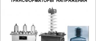
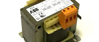
Isolation transformer
Conditions for connecting and operating isolation transformers
Equipment that complies with GOST 15543.1 and GOST 15150 standards is intended for operation in moderate and cold climates. Depending on the type of housing and purpose, it can be installed in closed spaces with natural air exchange and without artificial regulation of the internal microclimate, as well as outdoors under a canopy or in a dry, unheated room where there is free access to outside air.
To avoid mechanical stress, all busbars and wires must be secured. The distance from the windings of the isolation transformer to the wall or other grounded structure should be 300 mm. Preventive maintenance work on voltage distributors is carried out twice a year. They include operations to clean the windings, magnetic circuit system and cooling channels from dirt, dust and foreign particles.
In addition, during service maintenance, the reliability of bolted connections must be tested, for which torque wrenches and wet cleaning of the windings with a sponge soaked in a solvent or alcohol solution are used. The volumes and frequency of each type of operation directly depend on operating conditions. It is also recommended to carry out a visual inspection of the equipment from time to time.
Source
Application
The use of isolation transformers is especially necessary in premises whose operation is subject to increased electrical safety requirements. This applies to:
- basements;
- cable wells;
- objects with high humidity levels;
- gas hazardous places;
- when using a power tool of the first electrical safety class.
At home, such devices can be installed in bathrooms, swimming pools and other technical rooms where a higher level of protection against electric shock is required. It is possible to connect them to boiler units.
What is a 220/220 isolation transformer for and how does it work?
Hello, dear subscribers and visitors of my channel. Today’s material will talk about such an interesting and not so common product (in the private sector) as a 220/220 Volt isolation transformer. We will also talk about the principle of its operation and the main scope of application. So, let's begin.
How does an isolation transformer work?
At its core, the operation of an isolation transformer (IT) is practically no different from the operating principle of the most ordinary step-up and step-down transformers. It also undergoes transformation processes of electrical energy.
There is only one difference, which is that identical windings are installed on the magnetic core in the isolation transformer. They have the same parameters such as: thickness of the winding wire, number of turns and insulation.
In this case, during the transformation process, both the magnitude and vectors of the voltage induced in the secondary winding are completely preserved.
Why is an isolation transformer needed?
First of all, it is necessary in order to separate the voltage circuits of electrical appliances from the main electrical network through the use of isolated power windings.
So, RT is necessary in order to raise electrical appliances to the maximum level of safety, and, therefore, serves to reduce electrical injuries in general.
Connecting an isolation transformer to the network
So, as an example, let's study a typical new wiring of a residential building, made with a three-wire cable, where in addition to the phase and working zero, there is also grounding.
Electrical appliances connected to such a network are grounded, and in the event of a leakage current, the RCD installed in your distribution panel turns off the damaged area or the entire house at once.
But there are devices that do not have the possibility of grounding. So, it is in this case that we will need RT, because it is through it that we need to connect electrical appliances without the possibility of grounding.
The whole point is that in the secondary circuit of the RT, an electrical circuit of its own and isolated from the general network and, accordingly, the ground is created.
This means that the potential difference is present exclusively at the terminals of the isolation transformer, and if a situation arises when the insulation of an electrical device is damaged or the line itself is damaged, such a device will not pose any danger to humans due to the lack of connection from the network to ground potential.
Everything is fine, but even in this seemingly completely safe option there are risks of electric shock, so you must strictly follow the rules.
Safety rules when using an isolation transformer:
1. Do not touch the output terminals of the transformer at the same time.
2. The primary winding, which is connected to the general network, must be grounded.
3. It is prohibited to ground the housings of electrical appliances connected to the network after the isolation transformer.
4. It is allowed to connect only one electrical device via RT. If you need to connect several devices at once, then the use of special voltage monitoring devices is strictly necessary.
Efficiency and scope of RT
Isolation transformers are mainly used in places where there are increased requirements for electrical safety:
· Rooms with high humidity.
· Used when working with power tools classified as electrical safety class 1.
· Connection of medical devices for stationary installation.
So, an isolation transformer is a fairly useful device that significantly increases electrical safety.
Source
Safety concerns regarding AC power cannot be overstated. Take for example the familiar 220 volts. Under certain conditions, even this low voltage can be deadly, despite the fact that it is present in every modern outlet.
The main danger of a conventional power socket is that sometimes it is not necessary to touch two network wires at the same time; sometimes it is enough to touch a phase that accidentally falls on the body of the device, while standing on the ground or holding a conducting battery with your hand. This is already enough to cause cardiac arrest. To protect against such troubles, isolation transformers are used.
An isolation transformer is a transformer whose transformation ratio is equal to unity, that is, the number of turns in the primary winding is equal to the number of turns in the secondary winding (n1/n2 = 1). The function of such a transformer is to safely supply mains power to consumers. This is achieved by isolating the primary winding circuit from the secondary circuits, and the secondary circuit is not grounded in principle in order to completely eliminate the possibility of shorting the secondary current in the direction of grounding.
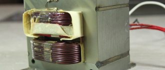
The primary and secondary windings of the isolation transformer are galvanically isolated from each other using reinforced or double insulation, or by installing a protective screen between the windings. In addition, the windings are usually separated (spaced out into different parts of the magnetic circuit) physically. And the wires with which the windings are wound have approximately equal or completely identical characteristics.
The secondary circuit, as noted above, is isolated from the ground loop - this is a fundamental feature of an isolation transformer. And although the efficiency of an isolation transformer is around 85%, this is considered advisable for the sake of achieving safety; it is not for nothing that isolation transformers are also called “safety transformers”.
Isolation transformers must be equipped in any rooms of particular danger and high humidity, as well as places with increased safety requirements. For example, in a bathroom or sauna the humidity is always high, here, as a rule, there are many metal products with unstable grounding, water often flows, and in general the conditions are not suitable for using electricity in the presence of people.
But even when dealing with “safe” isolation transformers, certain rules should be followed. It is unacceptable to touch two terminals of the secondary winding of the isolation transformer at the same time. Touching one of the terminals will not cause any danger, since the source circuit of the dangerous EMF variable will remain open. But if you touch both terminals of the secondary winding, it will be tantamount to being hit by a regular (without isolating transformer) socket.
The primary circuit of the isolation transformer must be equipped with an RCD. Under no circumstances should the housings of devices powered by an isolating transformer be grounded, because even in the event of a breakdown of the insulation on the housing, the current should not be able to short circuit to the ground, and if the housing is grounded, then there is a danger of additional paths for the current appearing, in this case it makes sense the use of an isolation transformer will simply be lost.
If you liked this article, share a link to it on social networks. This will greatly help the development of our site!
Source
Advantages and disadvantages of the device
The use of isolation transformers allows you to achieve the following advantages:
- increase the service life of electrical appliances;
- reduce the amount of electric current during a short circuit;
- additional protection during operation of electrical equipment;
- improve the quality characteristics of the electrical network;
- filter out high frequency interference.
The disadvantage of these devices is the additional complexity of the home or industrial network and the inability to provide complete protection against electric shock.
Device
Today, isolation transformers 220/220V, 380/380V are on sale. They reduce the voltage for powering devices with direct current to 120 V, and alternating current to 50 V. The minimum voltage in the network will be 24 V.
The design of isolation transformers is based on an operating principle that is associated with the occurrence of galvanic isolation of low voltage. To achieve this, the windings are reinforced with double or triple electrical insulation. The induction of electricity obtained by passing current through the windings occurs in the second coil.
The purpose of the unit is, among other things, to eliminate voltage surges in the network. It is able to protect household appliances, industrial equipment from breakdown, and a person from electric shock.
How to make your own isolation transformer
It is not difficult to make a low-power device yourself, if you have similar skills and basic knowledge in the field of electrical engineering.
Sequence of operations:
- two half windings are made on two identical cores - the coils are divided in half;
- a pair of half windings are connected in series;
- Additionally, you can equip the device with a throttle or stabilizer.
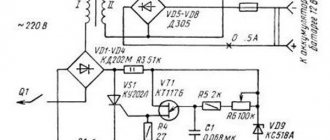
A more detailed diagram of the device and the order of connecting the half-windings is shown in the diagram:
The device can be used to power a workshop or other auxiliary room. Before connecting to a stationary power supply, the device must be tested with a small electric current. An ordinary low-power lamp is suitable as a consuming device.
But if the home handyman does not have enough electrical knowledge and no experience in such work, it is recommended to contact a specialist of the appropriate profile.
Connection diagrams
Isolating transformers are connected to a 220 Volt network. The windings are connected to each other in series, they are fixed on the frame.
The type of connection depends on the security level of the model. Rated primary voltage is not more than 1,000 VAC. Rated frequency within 50 Hz. First of all, the power supply to the mechanisms is turned off. Isolation is required in the galvanic circuit. Next, the unit is connected.
It is unacceptable to ground the housing of devices that are powered by an insulating unit. The current should not be shorted to ground, creating additional paths for the current. Otherwise, the use of a transformer becomes meaningless.
The device is installed both in enclosed spaces with natural air circulation and in open areas under a canopy. The distance to the wall must be at least 300 mm. Twice a year, preventive maintenance should be carried out to remove dirt from the windings and channels. Visual inspections should be carried out regularly.