- home
- Measuring instruments
If, when measuring electric current, you use an ammeter with a limit of 1, 5 or even 10A, and the load will be greater than this limit value of the ammeter, then a measuring current transformer with the required coefficient can help you.
Let me remind you that the ammeter is connected in series to the electrical circuit. How will the ammeter be connected when using a current transformer?
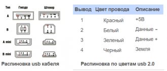
In general, the TT will have two measuring leads for connecting an ammeter. The connection of the primary current to the CT occurs in series, but has features depending on the type of device, which we will discuss below.
Schemes for connecting ammeters through current transformers
In current measurement circuits, both when connecting devices directly and when connecting them through measuring current transformers, only ammeters are used.
Schemes for connecting ammeters through current transformers are shown in Fig. 1. The current transformer provides a measurement error corresponding to its accuracy class only when measuring current in a certain range, and the load resistance in the secondary winding should not exceed a specified value. Thus, the accuracy class of current transformers of type TS-0.5 with a load resistance of 1.6 Ohms will be 1.0. When the load resistance increases to 3 ohms, the accuracy class decreases to 3.0, and when a load with a resistance of 5 ohms is connected to the secondary winding it becomes equal to 10.0.
Resistances when drawing up a real circuit can be estimated approximately as follows.
Resistance of connecting wires Rc = ρ l/S,
where ρ is the resistivity of the wire material (for copper wires ρ = 0.0175 μOhm x m, for aluminum wires ρ = 0.028 μOhm x m); l — length of connecting wires, m; S - cross-sectional area of wires, mm 2.
The total resistance of contact connections Rк can be taken equal to 0.05 - 0.1 Ohm.
The resistance of the device Z can be found in the reference book, indicated in the device passport or on its scale.
Rice. 1. Circuits for connecting ammeters through a current transformer: a - simple, b - with an intermediate transformer, c - for measuring currents exceeding the rated current of the transformer, d - with an intermediate transformer, with several ammeters, e - with an ammeter switch, c - c three-phase circuit with three ammeters, and the same with one ammeter with a switch.
The simplest and most common circuit for measuring current with a transformer in the circuit is shown in Fig. 1, a.
The current measured using this circuit is I = (I t n1 x I n x n)/(I t n 2 x N) = ktn x n x D p,
where I t n1 and I t n 2 are the rated primary and secondary currents of the current transformer; ktn = It1/It2 - transformation ratio; D p = Ip/N—device constant; D = Dp x k x t n - constant of the measuring circuit, n - instrument readings in scale divisions, N - number of divisions marked on the instrument scale, I p - full deflection current of the needle.
The accuracy class of the transformer is selected according to the accuracy class of the measuring device in accordance with table. 1.
Example. Let the ammeter RA have a scale with N = 150 divisions and a measurement limit of I p = 2.5A. In the measuring circuit in Fig. 1, and it is connected through a current transformer with rated primary and secondary currents I t n1 = 600 A and I t n 2 - 5 A, respectively. When measuring the current, the needle of the measuring device stopped against division n = 104.
Let's find the measured current. To do this, we first determine the device constant: D p = Ip/N = 2.5/100 = 0.025 A/div.
Then the constant of the circuit with the measuring transformer and the device D = (I t n1 / I t n 2) D p = (600 x 0.25)/5 = 3 A/div.
We find the measured current as a result of multiplying the constant circuit by the number of divisions shown by the arrow of the device: I = nD = 104 x 3 = 312 A.
When measuring current remotely, when the length of the connecting wires between the current transformer and the ammeter exceeds 10 m, or to simultaneously repeat readings in different places, it is necessary to connect a load whose resistance exceeds the permissible value into the secondary winding of the current transformer. In this case, use the diagrams shown in Fig. 1,b,c, in which an intermediate current transformer with a primary current of 5 A and a secondary current of 1 or 0.3 A is used.
In the first case, the load resistance of the secondary winding of the intermediate transformer can be increased to 30 Ohms, and in the second - up to 55 Ohms. To determine the current using this circuit, it is necessary to multiply the current value by the transformation ratio of the intermediate current transformer.
If, when conducting tests in installations up to 1000 V, there is a need for switching in the secondary circuit of the current transformer, then the circuit shown in Fig. 17, d, in which any switch with two poles is used. After closing the secondary winding of the transformer, you can make the necessary switchings at points 3 and 4 of the circuit. During all switching, the secondary winding is closed through the switch contact connected to points 1 and 2. Switching in the main circuit of current transformers is carried out only when the voltage is removed.
To measure current exceeding the rated current of one current transformer, you can use the circuit shown in Fig. 1, in. Current transformers T1 N and T 2N are connected so that only half of the current I flows through the primary windings. The secondary windings of these transformers are included in the primary winding of the intermediate transformer T 3 N, which measures the sum of the secondary currents of the transformers T 1 N and T2N, and the ammeter is included in the secondary winding of the intermediate transformer.
The primary winding of the intermediate transformer must be designed for the sum of the secondary currents of the transformers T 1 N and T2N. Then the relation I = (kt1n + kt2n) x kt3n x D n x n = Dn is valid, where all notations correspond to those given earlier.
Sometimes during testing it becomes necessary to measure current in three-phase three and four-wire networks. In three-wire three-phase circuits without a neutral wire, measuring circuits with two current transformers are used to measure the current of each phase (Fig. 1, e).
In this case, current Ib of phase B flows through ammeter RA1, current Ic of phase C flows through ammeter RA2, and current Ia = Ib + Ic of phase A flows through ammeter RA2. The current measured by each of the devices is found by the expression I = (I t n1 x I n x n)/(I t n 2 x N) = ktn x n x D n = Dn.
When testing three-phase electrical machines, a modification of this circuit is more often used to measure current in phases, characterized by the presence of switch S1 (Fig. 1g). The switch allows you to use only one ammeter and reduce the error in measuring current in phases by eliminating the difference in instrument readings within their accuracy class. The contacts of this switch must ensure continuous switching of the secondary circuits of the current transformers.
How to measure current in a circuit
To measure electric current in a circuit, it is much more convenient to use modern devices - multimeters or clamps, especially for one-time operations. But a stationary ammeter is suitable for situations where you plan to constantly monitor the current strength, for example, to monitor the charge of a battery or battery in a car.
Direct current
A break in the electrical circuit is organized before the start of measurements with the voltage turned off. Even in low voltage circuits, you can cause the battery to short out, which will instantly lead to loss of electrical charge. Next, consider an example of measuring a DC circuit using a multimeter, for this:
Rice. 2. Using a multimeter to measure DC current
- connect the probes to the corresponding inputs in the tester - black to COM, red to the connector marked mA, A or 10A, depending on the device;
- using “crocodiles”, connect the tester probes to the measurement circuit in series;
- set the switch to the desired type of current and measurement limit;
- you can connect the load and take measurements, the multimeter display will display the desired value.
But note that you should connect the multimeter for a short period of time, as it may overheat and fail.
Alternating current
An AC voltage circuit can be measured with either a multimeter or a clamp meter. But, due to the danger of alternating household voltage for human life, it is more advisable to perform this procedure with pliers without measuring probes and without breaking the circuit.
Rice. 3. Using Clamps to Measure AC Current
To do this you need:
- switch the knob to the position of alternating currents to the desired load position; if it is initially unknown, then immediately select the maximum range;
- press the side bracket, which will open the pliers;
- Place the current-carrying wire inside the clamp and release the button.
- The measurement data will be displayed on the display; if necessary, they can be recorded with the corresponding button.
Measurements can be taken on both insulated and bare conductors. But note that only one conductor should fall into the girth area; it will not be possible to measure two at once.
Connection diagrams for an ammeter through a current transformer, how to choose
Current measurements in networks are carried out using electrodynamic instruments. But in order to check the power, it is necessary to correctly connect the devices to the circuit. The article presents a descriptive diagram of connecting an ammeter through current transformers. Power networks are under high voltage, so connecting conventional testing tools directly will not work. For these purposes, there are downward blocks. They reduce the power to the limits required by the measuring instruments.
Purpose and design features of instrument transformers
Step-down blocks are used in measuring and computing systems. They have one main and several additional coils. Ammeters are connected to a secondary circuit, where the primary and secondary currents are directly proportional to each other. The current strength depends on the number of turns and the internal resistance of the wire. This voltage is safe for operating personnel and allows work to be carried out without risk to life.
The windings of the measuring units are made on a ferrite rod. When voltage is applied to the main coil, a magnetic field is generated that varies in space. Such oscillations generate electromotive force in the secondary windings.
Connecting ammeters via current transformers
To account for active energy in AC networks with different numbers of phases, induction or electronic ammeters are used, which provide measurement accuracy corresponding to the class of the device. As the resistance increases, it will decrease.
In a simple circuit, the measuring instrument is connected in series with a load added.
It takes readings from the energy consumer. This circuit provides the optimal measurement option, since the total circuit resistance is minimal. However, there are more complex schemes; the design feature depends on the goals and purpose of accounting.
Types of ammeters
Based on the type of reading device, ammeters are divided into devices with:
— with a pointer indicator;
- with light indicator;
- with a writing device;
According to the operating principle, ammeters are divided into:
1. Electromagnetic – intended for use in direct and alternating current circuits. Typically used in conventional AC electrical installations with a frequency of 50 Hz.
2. Magnetoelectric - designed to record the current strength of small values of direct current. They have a magnetoelectric measuring device and a scale with graduated divisions.
Connecting ammeters to the network
We come across current measurement very often. In order to find out the power of the device, the cross-section of the cable for its power supply, heating of wires and other elements - it all depends on the current strength. In order to directly measure this force, they came up with a device called an ammeter. The ammeter is connected to the measured circuit only in series. Why? Let's look at it a little lower.
As is known, current strength is the ratio of the number of charges ∆Q that passed through a certain surface during time ∆t. In the SI system it is measured in amperes A (1 A = 1 C/s). In order to measure the number of passed charges, the ammeter must be connected in series to the circuit.
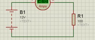
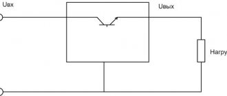
To minimize the influence of the ammeter's measuring resistance and, accordingly, reduce power losses during measurement, it is made as small as possible. If an ammeter with such internal resistance is connected in parallel, a short circuit will occur in the circuit. Example of a connection diagram:
Direct current is measured by direct assessment devices in the range of 10 -3 - 10 2 A, electronic analog, digital, magneto-electric, electromagnetic, electrodynamic devices - milliammeters and ammeters. If the current is over 100 A, use a shunt:
Shunts are usually made for different currents. A shunt is a copper plate that has a certain resistance. When current flows through the plate, according to Ohm’s law U=I*R, some voltage drops on it, that is, between points 1 and 2 a voltage arises that will affect the coil of the device.
The shunt resistance is usually selected from the following ratios:
Where Ri is the resistance of the measuring winding of the device,
is the shunt coefficient, I is the measured one, and Ii is the maximum permissible current of the measuring mechanism.
If alternating current is measured, then it is important to know what value is being measured (amplitude, average, effective). This is important, since all scales are usually graduated in actual values.
Variable values above 100 µA are usually measured with rectifier microammeters, and below 100 µA - with digital microammeters. For measurements in the range from 10 mA to 100 A, rectifier, electrodynamic, electromagnetic devices are used, which operate in the frequency range up to several tens of kilohertz, as well as thermoelectric devices, the frequency range of which is up to hundreds of megahertz.
To measure variable quantities from 100 A and above, instruments are used, but using current transformers:
A current transformer is a device in which the primary winding is connected to a current source (or, as can be seen from the figure below, the primary winding is “put on” a bus or cable), and the secondary winding is connected to the measuring winding of some measuring device (the winding of the measuring device or sensor must have low resistance).
To measure various types of currents, various methods and means are used. In order to correctly measure the required value without causing any harm, each measurement method must be used correctly.
What is an ammeter, its types
An ammeter can measure current in any electrical circuit. This device is easy to recognize; it is designated by the Latin letter A. Since the current can be of different sizes, ranging from milliamps and higher, there are devices of different power or universal ones, in which the measurement limit changes. Moreover, for direct and alternating current, different types of ammeters are needed.
- Electromagnetic version.
- Magnetoelectric.
- Thermal.
- Detector type.
- Induction.
- Electrodynamic system.
- Photovoltaic.
- Thermoelectric.
A magnetoelectric device can determine the current strength in circuits connected to a constant voltage. Detector and induction type - measure alternating currents. All other types can be universal.
Electrodynamic and magnetoelectric ammeters have high sensitivity and accuracy of readings.
How to connect an ammeter to an AC circuit, ampere meter
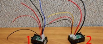
An example of such a device - model DSN - VS 288, consists of:
Expert opinion
It-Technology, Electrical power and electronics specialist
Ask questions to the “Specialist for modernization of energy generation systems”
Scheme for connecting the meter through current transformers: how to connect the Mercury electric meter and other models The maximum, including emergency, load indicator in a controlled installation should not exceed the rated characteristics of the transformer. Ask, I'm in touch!
Ammeter: purpose, connection diagrams, types, characteristics
Definition
The ammeter is connected in series with the section of the electrical circuit where the current is supposed to be measured. Since the current that it measures depends on the resistance of the circuit elements, the resistance of the ammeter should be as low as possible (very small). This allows you to reduce the influence of the current measuring device on the measured circuit and increase their accuracy.
The instrument scale is calibrated in µA, mA, A and kA, and depending on the required accuracy and measurement limits, a suitable device is selected. An increase in the measured current is achieved by including shunts, current transformers, and magnetic amplifiers in the circuit. This allows you to increase the limit of the measured current value.
Ammeter connection diagrams
Figure - Diagram of direct connection of an ammeter
How to connect an analog ammeter?
- home
- >Answers to questions
If you have a regular analog ammeter and you don’t know how to connect it, then this is very easy to do. In addition to the ammeter, you need a SHUNT, since the ammeter measures the voltage drop across the shunt. The connection diagram for an ammeter with a shunt looks like this (figure below). If you don’t have a shunt, you can make one yourself, and more on that later in the article.
>
If you have an ammeter and there is no shunt for it, you can make one yourself. You can take a piece of copper wire as a shunt; the thickness of this wire depends on the current that will be measured. For example, for currents up to 10A, you can take a wire with a cross-section of 1.5 kW, if the current is up to 30A, then it is better to take a wire of 2.5 kW.
A length of approximately 30 cm is needed; it must be completely stripped of insulation. Next, we connect this wire instead of the shunt; in the picture below, I think everything is clear.
>
Such a shunt is no worse than the factory one, except, of course, for its appearance. And calibrating an ammeter is quite simple. We need a second ammeter, which is connected in series with our shunt. It can be before our homemade shunt, or it can be after. We connect the energy consumer to the power source and see how much the second ammeter shows. Next, we look at our ammeter and use a homemade shunt to move the contacts of the ammeter, bringing them closer or further away from each other so that the readings on both ammeters are the same. That's all, when the ammeter readings are the same, all that remains is to solder the contacts from the ammeter to the shunt so that they do not move and the ammeter does not go astray.
After this, the ammeter is ready for use, and the homemade shunt can be placed in some kind of housing or hidden from view if you don’t like it. In addition, the shunt can be made not only from copper wire. A metal plate will do, even a simple bolt where you can use nuts to clamp the wires from the ammeter and adjust the distance between the wires to calibrate the device.
Below is the photo of my ammeter with a homemade shunt.
>
I did not measure the length of the active zone of the shunt, so I cannot say at what distance to solder the wires from the ammeter. Well, the cross-section of the copper wire may be different and the ammeter itself may also be different, so you still have to calibrate it. I did this using a multimeter. A few more photos of an ammeter with a homemade shunt.
>
This is what it looks like from the reverse side, you can see how the wires come out of the ammeter and how they connect to this copper shunt
>
I think it’s clear how the ammeter works and how to connect the shunt. The shunt is connected in series, that is, into a break in one of the wires going to the energy consumer. You can place the shunt either on the plus side or on the minus side. If the ammeter needle deviates in the wrong direction, then you just need to turn the shunt over. And so the ammeter measures the voltage drop across the shunt, the voltage drop there in millivolts.
In my opinion, almost all factory shunts have a voltage drop of up to 75 mV, and the shunt must be selected according to the characteristics of the ammeter. If the ammeter is 50A and 75mV, then you need to buy the same shunt, otherwise the ammeter will show incorrectly.' I hope this information helped you, thanks for reading and leaving comments.
Current and voltage transformers
Before we talk about instrument transformers, a little theory. Transformer is an element of an electrical circuit that converts the value of alternating voltage. Transformers can be:
- step-down , producing a lower voltage at the output than at the input;
- increasing , performing the opposite transformation;
- separating ones that do not change the voltage value, used for galvanic isolation between sections of the electrical network.
Step-up and step-down transformers are reversible: if we apply the rated output voltage of the transformer to its secondary winding, we will get the rated input voltage on the primary winding.
The opposite picture occurs with currents in the windings. The primary winding is designed for a current corresponding to the rated power of the transformer. Both the cross-section of the magnetic core and the diameter of the winding wire of the primary winding are selected for the power.
The current in the secondary winding of a step-down transformer can be greater than the current in the primary winding as many times as its voltage is lower. This ratio is called the transformation ratio. Therefore, the cross-section of the winding wire of the secondary winding of the step-down transformer is larger. For a downgrader, it’s the other way around. For the separating one, everything is the same.
- Why are voltage transformers needed?
- Voltage transformers and their design
- Why are current transformers needed?
- Operating principle and design of current transformers
- Video about current transformers
Why are voltage transformers needed?
In electrical installations up to 1000 V, voltage measurements are made by connecting voltmeters directly to buses or other controlled sections of the network. But in networks of 6 kV and above this is impossible because:
- When measuring high voltage, it is necessary to reduce its value to a size perceived by the frame of a pointer device or an electronic digital converter. Resistive dividers will not perform the task with the required accuracy, and the use of a step-down transformer will make the device bulky;
- The insulation of the conductors for connecting the device must withstand the rated voltage of the electrical installation . In addition, the phase-to-phase distances required by the PUE must be observed. This is impossible to do.
Voltage transformer NOL
Therefore, for measurements, the voltage value is reduced, and for this you need a voltage transformer
Voltage transformers and their design
Whatever voltage the primary winding of the voltage transformer is designed for, the voltage on its secondary winding is standard - 100 V. This was done for unification: the electricity meter does not care which electrical installation it operates in - 6 kV, 10 kV or more. If it is intended for operation with voltage transformers, its technical characteristics in the “rated voltage” column indicate: “3x100 V”. The number “3” means that three phases are connected to it for measurements.
Structurally, voltage transformers are made as follows:
- single-phase conversion element in its housing; for three-phase voltage, three such transformers are installed;
- one housing contains a transformer to convert all three phases .
Three-phase voltage transformer NAMI
The primary windings of three-phase transformers are connected in a star.
Voltage transformers have several secondary windings:
- winding for metering with an accuracy class of 0.5s;
- winding for measuring instruments – accuracy class 0.5;
- winding for relay protection – class 10P;
- winding for open delta - class 10P.
The accuracy class matters when accounting and measuring. But there is one more nuance: the measuring winding of the transformer operates in the declared accuracy class, unless the permissible load on it is exceeded. Therefore, along with the class, the permissible power , which cannot be exceeded.
Voltage transformer NOM-10
Another factor that changes the accuracy class is the resistance of the connecting conductors . If the meter or ammeter is located far from the voltage transformer and is connected by a control cable with conductors of insufficient cross-section, then the voltage value on it will be less than on the transformer.
The terminals of the secondary winding of the voltage transformer used for commercial metering are covered with a lid and sealed.
The primary windings of voltage transformers are protected by fuses. Fuses were also used to protect secondary windings, but now they have been replaced by circuit breakers.
Three single-phase ZNOL transformers assembled together
Now let’s remember the theory at the beginning of the article. The main danger when working on voltage transformers is the phenomenon of reverse transformation . If for some reason the secondary winding receives a voltage of 100 V, then the primary winding will be under the rated voltage of the electrical installation. People working in the cell will be under voltage . Therefore, when taking a voltage transformer out for repair, measures are taken. Excluding reverse transformation.
Why are current transformers needed?
One of the reasons why current transformers are installed in electrical installations above 1000 V is the same as for voltage transformers. It is impossible to ensure isolation of circuits for connecting devices .
Ammeter-Voltmeter VAR-M02 on DIN rail, connection diagram, parameters
The voltammeter is produced in a plastic case with front connection of power wires and switched electrical circuits. Mounting is carried out on a DIN mounting rail with a width of 35 mm (GOST R IEC 60715-2003). The design of the terminals ensures clamping of wires with a cross-section of up to 2.5 mm2. On the front panel of the device there are digital indicators displaying the voltage and current values, and a button. The indicators have a high luminosity, ensuring that information can be read in any lighting conditions. The voltammeter does not require auxiliary power and is connected directly to the circuit being measured (terminals A1 and A2). Current is measured by contact and non-contact methods. Contactless using a built-in or external current transformer. To measure current in the range from 0.1 to 1A, it is necessary to connect the circuit with the measured current to terminal E and to terminal E2. To coordinate the ammeter readings, use the button to set the scale to 1A. To measure current in the range from 0.5 to 5A, it is necessary to connect the circuit with the measured current to terminal E and to terminal E1. To coordinate the ammeter readings, use the button to set the scale to 5A (set by default). To measure current in the range from 3 to 30A, it is necessary to pass the circuit with the measured current through a hole in the housing. To coordinate the ammeter readings, use the button to set the scale to 30A. To measure current in the range from 0 to 1000A, it is necessary to use an external current transformer. Connect the current transformer contacts to terminals E and E1. To match the current transformer used and the ammeter readings, you need to use the button to set the required transformation ratio (hold the button for 15 s, then briefly press to select the required ratio). In non-contact current measurement, a conductor carrying the measured current is passed through a hole in the housing.