Inserting from a list of equipment
- Click Schematic tab Insert Components panel Insert Component drop-down Equipment List. find
- Select the table file and click Open.
- If multiple sheets/tables are found in the data file, select the table to edit.
- Click OK.
- In the Options dialog box, determine whether the default settings will be used, or select a file with previously saved settings.
- Default Settings: View/Edit Settings options become available to change the default settings. Change the settings or click OK to continue pasting using the default settings.
- Read parameters: select a file (*.wde) to read parameters and click the “Open” button.
- (Optional) Click in the spreadsheet/table columns to determine the order of the data in the selected equipment list file. In the Equipment List Spreadsheet Options dialog box, assign column numbers to data categories (for example, Manufacturer, Catalog Number, and Functional Group).
- (Optional) Click Save Settings to save the settings to a file for later use.
- In the Options dialog box, click OK.
- In the Schematic Hardware (or Panel Hardware) list, view components by sorting or checking by catalog.
- Select the component to insert into the drawing.
- Make changes to the scale, orientation, or rotation angle of a component.
- Select a method for inserting a component into a drawing:
- Insert: Finds and inserts a schematic component (or panel) for the selected component in the equipment list.
- Specify file: Specifies the file to insert. Select an existing AutoCAD Electrical toolset component list file for the equipment list, or retrieve a new copy of the panel components data from the current project database.
- Convert Existing: (panel components only) inserts the data for the selected record into an existing non-AutoCAD Electrical toolset inserted block. The block is immediately converted to an AutoCAD Electrical toolset footprint.
- In the Insert dialog box, select the name of the block to insert from the list.
- Click OK.
Dynamic blocks in shields
The low-current 19″ cabinet is a dynamic unit, in which we can quickly change the height in units by selecting it from the list. It is not so easy to create such a block, since it contains both an array operation and a linear dimension, but it is not difficult to find on the Internet. When filling the cabinet, you can easily change its height.
You can conveniently make a switch into a dynamic block by selecting the required number of ports.
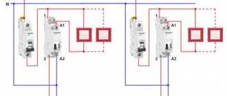
Automatic devices and RCDs are also easy to make dynamic. Here its value (visibility parameter) and purpose (attribute) dynamically change. It would be great to make another visibility parameter handle so that the letter of its phase appears on the machine, but AutoCAD does not allow you to make two selections in one block.
What does it give us if we select the denomination of the machine from a list of predetermined denominations, and do not write it over the machine in text, as I used to do myself, and as I see in many other people’s projects?
First of all, choosing a denomination from a list is simply faster than writing it down. Moreover, the denomination immediately appears exactly in the center of the machine and will not go anywhere. Secondly, you can easily change the denomination of a large number of machines at once. You need to select them and change the visibility setting in the properties window; it will change immediately for all selected elements.
It is extremely convenient to use a frame in sheets, which can be instantly changed from A4 to A3 and from horizontal to vertical.
System requirements
For 32-bit AutoCAD Electrical
- Operating system Windows 8 Enterprise, Professional, and Standard edition, Microsoft Windows XP Home or Professional (SP3 or higher), or Microsoft Windows 7 Enterprise, Business, Ultimate or Home Premium
- Intel Pentium 4 processor or dual-core AMD Athlon processor with at least 1.6 GHz and SSE2 support for Windows XP, or Intel Pentium 4 processor or dual-core AMD Athlon processor with at least 3 GHz and SSE2 support for Windows Vista or Windows 7
- 2 GB RAM
- 11 GB of free disk space for installation (12 GB for computers without the .NET component)
- Monitor with 1280x1024 resolution and True Color support
- Browser Microsoft Internet Explorer 7.0 or higher
- Pointing device compatible with Microsoft Mouse
- To install: Internet connection or DVD drive
For 64-bit AutoCAD Electrical
- Operating system Windows 8 Enterprise, Professional, or Standard edition, Microsoft Windows XP x64 Edition (SP2 or higher), or Windows 7 Enterprise, Business, Ultimate, or Home Premium edition
- Athlon 64 or AMD Opteron processor with SSE2 technology, Intel Xeon with support for Intel EM64T with SSE2 technology, or Pentium 4 with support for Intel EM64T with SSE2 technology
- 2 GB RAM
- 11 GB of free disk space for installation (12 GB for computers without the .NET component)
- Monitor with 1280x1024 resolution and True Color support
- Browser Microsoft Internet Explorer 7.0 or higher
- Pointing device compatible with Microsoft Mouse
- To install: Internet connection or DVD drive
Additional System Requirements for 3D Modeling
- Intel Pentium 4 or AMD Athlon processor 3 GHz or faster, or Intel or AMD dual-core processor 2 GHz or faster
- At least 4 GB of RAM
- 6 GB of free disk space (not including space required for installation)
- Video adapter with a resolution of 1280x1024 and 32-bit color depth (True Color)
- Workstation-class graphics adapter with 128 MB or higher memory, supporting Direct3D technology and Pixel Shader 3.0 or higher
Setting Terminal Types
- In the PLC Database File Editor dialog box, right-click Terminal Type 1 and select Edit Terminal from the context menu.
The Select Terminal Information dialog box appears. There are three categories for top symbols: Top Input, Top Output, and Top Terminal. The Top Input and Top Output categories consist of addressable terminals, and the Top Terminal category consists of non-addressable terminals. - In the Select Terminal Information dialog box, select Top Input.
The available terminals in that category, as well as the terminals that have been recently used, appear on the screen. All these terminals are slightly different from each other. This may be a terminal with an input wire connected, or terminals with both input and output wires connected, or terminals with no wires connected. - Select the picture "Module - Information - Input - I/O Point - Wire - Left" and then click the "OK" button.
The selected terminal is assigned to the Terminal Type field in the PLC Database File Editor dialog box. AutoCAD Electrical examines the inserted block by tracking the attributes that appeared when the block was inserted. Some of these attributes may have preset values that you can override. These values are shown in the table below the list of terminal types. - In the PLC Database File Editor dialog box, select the following seven terminals, right-click and select Edit Terminal.
Note: You can select multiple fields for editing at once by dragging the cursor across all adjacent fields or by pressing the Control key while selecting non-adjacent fields. - In the Select Terminal Information dialog box, select the Input category and explore all available terminals.
- Select the terminal "Input-I/O Point-Wire Left" and click "OK".
The selected terminal type will be assigned to all seven terminals simultaneously. - In the PLC Database File Editor dialog box, right-click the last terminal and select Edit Terminal.
- In the Select Terminal Information dialog box, select the Terminal category.
- Select the Terminal Point-Wire Right terminal and click OK.
Type 4 pin list assignments
You can configure subcategories of Type 4 pin combinations to apply the combinations of each subcategory to specific pin types. By assigning information from the PINLIST field to Type 4, you can also track and configure the number of terminal symbols on a schematic that can be associated with a given terminal tag ID.
Contact filtering for specialized applications
You can configure subcategories of Type 4 pin combinations to apply the combinations of each subcategory to specific pin types. To further filter the pins available for a given child pin, enter a code consisting of the number "4" and a letter into the pin list entry. On the pin side, the PINLIST_TYPE attribute (or additional Xdata of the same name) must be set to the value corresponding to the code in the pin list line (consisting of the number "4" and a letter).
For example, this device has five different types of normally open contacts. Three of them are designed to start the engine, and two are auxiliary control contacts. Two different schematic symbols are created, one representing the high-load motor starter contact and the other representing the auxiliary contact. For the motor starter contact graphic, set the PINLIST_TYPE attribute to "4C"; For an auxiliary contact graphic, set this attribute to "4A". In the _PINLIST database table, encode the pin list information associated with a given part number as entries of type "4": enter "4A" if the pin combination is for an auxiliary contact, and "4C" if it is intended for motor starter contact.
4A,1L,2L;4A,1R,2R;4C,L1,T1;4C,L2,T2;4C,L3,T3
After you insert any of these symbols and associate them with a parent object, AutoCAD Electrical toolset reads the PINLIST_TYPE value of that symbol. Pin combinations that do not match the inserted component type are filtered out. When you insert a motor starter normally open auxiliary contact (with the PINLIST_TYPE attribute preset to 4A), AutoCAD Electrical toolset starts the process of selecting the next available 4A type combination from the pin list - 1L/2L or 1R/2R. When you insert a motor main contact symbol (with a predefined 4C value for the PINLIST_TYPE attribute) into AutoCAD Electrical toolset, AutoCAD Electrical toolset starts the process of selecting the next available 4C type combination from the pin list (L1/T1, L2/T2, or L3/T3).
Application for multi-pole terminal blocks
Attributes of symbol blocks
| CODE | This attribute value provides a link between the symbol block on the circuit template drawing and the section on the circuit code sheet. The value of this attribute is matched to the value in the CODE column on the circuit code sheet for the selected template. |
| ORDER | The value of this attribute controls the order in which elements are displayed and inserted in the net. Designation blocks are processed in order, from smallest to largest. Designation blocks that are assigned the same ORDER values are linked together and processed as a group. For example, to adjust the spacing between wires of a 3-phase bus, three blocks of designations are used with common values for the CODE and ORDER attributes. The ORDER value can be an integer or a decimal number. Decimal numbers for order values make it easy to add a block of notation between two other blocks without completely reordering. |
| MISC1 | The value of this attribute contains various values, operations, and flags intended for annotation. The annotation value format is <attribute name>=<attribute value>. Operations can contain embedded expressions or AutoLISP programs. Flags are keywords that, for example, allow the connection of child and parent contacts or redefine the directions for creating multi-pole circuits. Flag codes include the following codes:
|
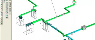
Obtaining preliminary floor fields with cables and cable-supporting products
Initially, a set of text objects is created, filled in, and included in the completed template.
A string of 4 text objects contains:
- text of the field showing the layer where the line is located;
- text that associates a layer with a specific cable brand;
- product article or standard specified in the register;
- field consisting of the length of lines and segments.
The required number of copies of this string is created and distributed across layers. Using the “Quick Select” function, a selection of the required parts of the drawing is created.
is created , the diagram of which provides the necessary selection of text objects and geometric modules. Unnecessary objects are hidden and a formula is created, indicated in the line for the floor.
The panel diagram in the apartment provides for a floor breakdown and division of the total estimate, indicating the number of equipment and cables operating on the required floor, which is repeated for each layer.
Benefits of purchasing an Autodesk Subscription:
An Autodesk subscription is the only way to guarantee receiving new versions of the software, because... the Upgrade procedure has been removed from Autodesk price lists since March 6, 2015 (more details). Therefore, by purchasing Autodesk software without a subscription, the Customer will not be able to update the version of the purchased software product in the future.
And taking into account Autodesk's intention to completely switch to a temporary licensing scheme for a number of software products, purchasing a permanent license with a subscription is now the only way to guarantee ownership of the most current perpetual version of the purchased software
One of the benefits of an Autodesk Subscription is the right to use previous versions of software, which allows you to save on hardware upgrades, as well as migrate to new versions when you need it.
An Autodesk subscription allows you to use Autodesk products outside the workplace (on business trips, on your home PC, etc.).
Customers with an Autodesk Subscription are eligible for technical support. Customer questions posed through the Subscription Center will be responded to by Autodesk technicians within 24 hours.
Subscribers are entitled to use Autodesk cloud technologies, which include 25GB of file storage and sharing per subscriber and the right to perform rendering, optimization, analysis and other complex processes in a timely manner on the power of Autodesk360.
Ribbon interface of the ACADE, 2D drawing and annotation space
Nowadays you won’t surprise anyone with a ribbon interface. The ribbon interface is designed to give you quicker access to core AutoCAD Electrical commands. The ribbon is a palette containing tools, commands, and controls designed to perform specific tasks. Tools are arranged on the ribbon into functional groups.
The Project tab of the ribbon interface contains the Project Tools and Other Tools panels.
The Schematic tab contains the Insert Components, Edit Components, Insert Wires/Wire Numbers, and Edit Wires/Wire Numbers and Other Tools panels.
A9cad
Please note that not all panels may be displayed due to limited screen width. Some panels can be hidden, as in this case the Other tools panel is hidden
To display it, move your mouse arrow to the right edge of the ribbon interface and hidden panels will appear.
The Panel tab contains the Insert Component Footprints, Terminal Footprints, Edit Footprints, and Other Tools panels.
The Reports tab contains the Outline, Dashboard, and Miscellaneous panels.
The Import/Export Data tab contains the Import and Export panels.
Ground terminal kz 31, kz 20 and 50
The Conversion Tools tab contains the Tools, Outline, Artboard, and Attributes panels.
There are also several other tabs that appear when the appropriate components are present.
These are the tabs Add-on, Online, Vault, etc.
We have considered only the main tabs.
Project Manager
The Project Browser palette appears on the left side of the screen. This palette is designed to work with the project as a whole and can be hidden until needed again or moved to any area of the screen.
At the top of the Project Manager there is a special menu for working with projects: opening existing projects or creating new ones, printing project drawings or archiving project files for forwarding, etc.
If you are working with a diagram and you do not need the Project Manager yet, you can close it by clicking on the cross. And if necessary, open it by going to the Project tab and clicking on the Manager shortcut.
A single click on the plus sign in front of the project name or a double click on the project name opens a list of drawings included in the project.
By right-clicking on the project name, a context menu opens with a number of additional commands for working with the project: activating the project, closing it, adding project descriptions, etc.
Double clicking on a drawing name opens that drawing. Right-clicking on a drawing name brings up a context menu for working with this drawing: open, close, copy, delete, etc.
At the bottom of the Project Browser palette there is a Details area. The type of information that is displayed on it is switched by the corresponding buttons: More details and Preview.
If you click More details, the window will display information about the project or drawing, depending on which element was selected. It is highlighted, not active!
When you click Preview, the selected drawing is displayed in the window.
Starting with AutoCAD Electrical 2013, you can drag and drop drawings and create folders in the Project Browser, allowing you to create a convenient project structure.
About the product
AutoCAD Electrical software is a dedicated solution based on AutoCAD that allows you to quickly create electrical diagrams and easily access extensive catalogs of required parts. AutoCAD Electrical helps you increase productivity, eliminate the risk of errors, and ensure accurate information transferred to production. AutoCAD Electrical's automation of common tasks and extensive symbol libraries enable you to quickly and efficiently develop electrical control system designs. AutoCAD Electrical uses multi-vendor component catalogs to speed up the design process. The AutoCAD Electrical content library contains more than 650 thousand parts and symbols. The user can quickly design electrical control systems by selecting standard devices from a menu.
The AutoCAD Electrical solution allows you to customize symbol libraries, cross-reference formats, and set rules for numbering wires and devices. AutoCAD Electrical includes a set of features to improve productivity and accuracy when working with PLC I/O device drawings. The PLC I/O module library contains more than 3,000 modules that help you quickly create drawings of the devices you need. The solution allows you to add new modules to the database. AutoCAD Electrical automatically numbers all wires and tags components according to established rules. AutoCAD Electrical includes tools to verify the accuracy of the generated circuits in real time, allowing you to identify and correct potential problems early in the design process.
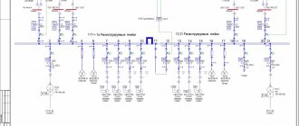
Breakdown of consumers into groups
- Calculate the power supply line.
- Calculate the probable voltage losses on the line.
- Select the appropriate wire cross-section.
- Predict the required number of cables (plus reserve).
- Draw up an electrical wiring diagram (taking into account the power of electrical appliances and lighting lamps) and link it to the floor plan.
Useful tips Connection diagrams Principles of operation of devices Main concepts Meters from Energomer Precautions Incandescent lamps Video instructions for the master Testing with a multimeter
Scheme-Scheme
A schematic-to-circuit relationship defines the various terminal representations of a circuit as a single multi-level terminal (also called ladder or multi-row). In a circuit drawing, each terminal image on the diagram represents one level of a multi-level terminal.
Wire
Note: Multiple terminal images for the same level are not currently supported.
The number of levels for a block is defined as a property of the terminal block block. Each level contains some characteristics such as label, number of wires per connection, left pin and right pin. Each terminal symbol on a diagram contains all the terminal block properties for each level, so deleting one terminal symbol does not delete the terminal block properties. When you change a terminal block property, all terminal symbols are updated.
Terminal images are connected by an identifier value, which is contained in the LINKTERM attribute or in additional data (Xdata). When you insert a terminal image, it defaults to being a stand-alone terminal (without connections) and has a new value of LINKTERM. When two terminals are linked, the value of the LINKTERM attribute is updated so that each terminal contains the same LINKTERM value. Changing or deleting the LINKTERM value breaks all connections present at the terminal.
To connect terminals on a diagram, you must first add terminal block block properties. The number of terminals that can be connected is limited by the number of levels specified in the terminal properties. Once you have defined the terminal properties, you can connect the terminals on the diagram to form a multi-level terminal in one of the following ways:
- Click Schematic tab Edit Components panel Connect Terminals.
A source terminal is selected, and then each terminal image is selected to link to the source. - In the “Insert/Edit Terminal Graphic” dialog box, click the “Specify” button. The edited graphic is associated with the specified terminal.
- In the “Insert/Edit Terminal Graphic” dialog box, click the “Add/Edit” button. The edited graphic is associated with any terminal on the circuit in the project.
Preformed circuits may contain connected terminals. Relationship data is preserved when a net is inserted. Copying a net also saves the relationship data in the copy of the net.
Copying Data from Single Line Symbols to Diagram Symbols
Transferring data from single-line graphical images to a diagram graphical image.
- Insert or edit a schematic component.
- Select "Software Used: Schematic".
- Select the "Show single line components (1-*)" checkbox.
- Select an existing single line component from the list.
- Select the categories or values you want to copy (descriptions, catalog values, function group/location, ratings).
- Click Copy Tag.
- Select TAG1 to reuse the tag value from the single line component.
- Click OK.
PEER_COIL TERMINALS, PEER_TERMINAL LIST
The _PINLIST table may contain two more PEER_ fields; they are used to define special cases in which two source devices are called for the same designation. For example, the part number for a reversible motor starter may contain information about the two parent contactor windings (one for forward rotation, one for reverse rotation). Each parent coil graphic must have its own pin list assignment. The coil pins and pin list data for the second coil are specified in the PEER_COILPINS and PEER_PINLIST fields for the overall part number.
Rate this article:
Inserting multiple wires
- Click Schematic tab Insert Wires/Wire Numbers panel Multi-Wire Bus. find
- Set the spacing between wires horizontally and vertically.
- Specify the beginning of the wires.
- Set the number of wires to three and click OK.
As you insert a wire, the command line displays the current wire type. The current wire type specifies the name of the layer in which new wires are drawn. To override the current wire type, you can enter "T" and select a new wire type in the Set/Edit Wire Type dialog box. The new wire type becomes the current one and the insert wire command continues. - If the insertion process starts at the component or bus level, select the component.
Slowly drag the cursor to the right until the second and third phase wires are secured to the corresponding vertical wires. The screen reflects the process of straight-line stretching of three wires. When stretching a three-phase wire, you can turn it at an angle; To do this, move the cursor outside the bus location line. To reverse the phase sequence during a turn, press the “F” key. - Right-click to set the end of the wires. Wires and wire connection points are inserted, and loops are automatically inserted where wires intersect.
Note: If the distance between two horizontal wires is relatively short, inserting breaks in the form of loops on the vertical wire crossing them can be avoided. The ability to insert a break in the form of a loop is determined by the value of the wire grip radius. To insert loop breaks, it is recommended to reduce the scaling factor or increase the distance between the wires.To connect a new three-phase wire to an existing bus (but with a reverse phase sequence), you should start this connection from the last wire of the existing bus. Move the cursor back through the remaining wires until connections are made, then move the cursor forward again. This results in a reverse phase sequence connection.
Inserting a component from the graphic menu
Using the graphical menu, you can insert an image by selecting its type, such as a LOCK button or a 3-way switch. You can then add annotation to the inserted graphic to include descriptions, catalog information, and more.
There are different graphical menus for different sets of libraries. You can set the graphical menu you want to use for a specific project on the Project Options tab in the Project Properties dialog box.
Dynamic switches and sockets
Here, for example, is a switch, the type of which can be easily changed by pressing the handle next to the block:
It takes about 10 minutes to create a dynamic switch block with several appearance options: 1, 2 or 3 keys, or to control a curtain. If we have classic electrics, then we add a “switch” type for different numbers of keys.
But here is a dynamic socket block, the type of which is easy to change.
You can add other types of sockets to the same block: internet, double internet, television, cable outlet, plug. Then you can simply put the required number of elements in a row, then change the type of each to the appropriate one. But it’s more convenient for me when a separate dynamic unit is made for low-current sockets.
Of course, it is also convenient to make the lamp a dynamic block: there will be, for example, a spotlight, a wall lamp, a chandelier. But since in the process of working on a project the type of lamps rarely changes compared to changes in sockets and switches, it is not necessary to make the lamp a dynamic block.
System requirements
For 32-bit AutoCAD Electrical
- Operating system Microsoft Windows 7 Enterprise, Microsoft Windows 7 Ultimate, Microsoft Windows 7 Professional, Microsoft Windows 7 Home Premium, Microsoft Windows 8/8.1, Microsoft Windows 8/8.1 Pro, Microsoft Windows 8/8.1 Enterprise
- Intel Pentium 4 processor or dual-core AMD Athlon processor with at least 1.6 GHz and SSE2 support for Windows XP, or Intel Pentium 4 processor or dual-core AMD Athlon processor with at least 3 GHz and SSE2 support for Windows Vista or Windows 7
- 4 GB (8 GB recommended) RAM
- 12 GB of free disk space for installation (12 GB for computers without the .NET component)
- Monitor with 1280x1024 resolution and True Color support
- Browser Microsoft Internet Explorer 9.0 or higher
- Pointing device compatible with Microsoft Mouse
- To install: Internet connection or DVD drive
- NET Framework Version 4.5
For 64-bit AutoCAD Electrical
- Operating system Microsoft Windows 7 Enterprise, Microsoft Windows 7 Ultimate, Microsoft Windows 7 Professional, Microsoft Windows 7 Home Premium, Microsoft Windows 8/8.1, Microsoft Windows 8/8.1 Pro, Microsoft Windows 8/8.1 Enterprise
- Athlon 64 or AMD Opteron processor with SSE2 technology, Intel Xeon with support for Intel EM64T with SSE2 technology, or Pentium 4 with support for Intel EM64T with SSE2 technology
- 4 GB (8 GB recommended) RAM
- 12 GB of free disk space for installation (12 GB for computers without the .NET component)
- Monitor with 1280x1024 resolution and True Color support
- Browser Microsoft Internet Explorer 9.0 or higher
- Pointing device compatible with Microsoft Mouse
- To install: Internet connection or DVD drive
- NET Framework Version 4.5
Additional System Requirements for 3D Modeling
- Intel Pentium 4 or AMD Athlon processor 3 GHz or faster, or Intel or AMD dual-core processor 2 GHz or faster
- At least 8 GB of RAM
- 6 GB of free disk space (not including space required for installation)
- Video adapter with a resolution of 1280x1024 and 32-bit color depth (True Color)
- Workstation-class graphics adapter with 128 MB or higher memory, supporting Direct3D technology and Pixel Shader 3.0 or higher