To identify an electric motor malfunction at home, in the absence of expensive professional equipment, there is nothing left to do but test the electric motor with a multimeter. With its help, you can identify most breakdowns, and you do not have to involve a specialist. So what should you do?
- De-energize the unit. If the resistance measurement is carried out in a circuit connected to the mains, the device will fail.
- Calibrate the device, that is, set the arrow to the zero position (the probes must be closed).
- Inspect the engine and find out if it is flooded, if there is a smell of burnt insulation or broken parts, etc.
Asynchronous, commutator, single-phase and three-phase motors are called using the same method; a slight difference in the design does not play a special role, but there are nuances that must be taken into account.
The most common malfunctions can be divided into two types:
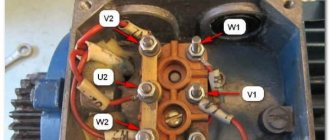
First, let's look at how to test a 3-phase electric motor with a multimeter. It has three coils connected in a delta or star configuration. Its performance is affected by the reliability of contacts, the quality of insulation and correct winding.
- First, check the short circuit to the body (keep in mind, the value will be approximate, since more sensitive instruments are required for accurate readings).
- Set the multimeter readings to maximum.
- Connect the probes to each other to ensure that the settings are correct and the device is working properly.
- Connect one of the probes to the engine housing; if there is contact, attach the second probe to the housing and monitor the readings.
- If there are no failures, touch the probe output of each of the three phases one by one.
- If the insulation is of high quality, the test should show a fairly high resistance (several hundred or thousand megohms).
It must be remembered that when measuring insulation resistance using a multimeter, the readings will be higher than permissible, since the EMF of the device does not exceed 9V. The engine operates at 220 or 380V. According to Ohm's law, the resistance value depends on the voltage, so make allowances for the difference.
Next, check the integrity of the windings by ringing the three ends included in the motor boron. If there is a break, further checking does not make sense, since this malfunction must first be eliminated.
Then check for shorted turns. With a delta connection, the fault indicator will be a higher value at ends A1 and A3. When connected with a star, the device shows an overestimated value in circuit A3.
Checking the commutator motor
Now let's move on to the above-mentioned nuances, because engines come in different types. How to test a commutator motor with a multimeter? The scheme for checking it looks like this:
What kind of lighting do you prefer?
Built-in Chandelier
- Turn on the device in Ohm units and measure the resistance of the collector lamellas in pairs.
- Then measure the resistance between the armature housing and the commutator.
- Check the stator windings.
- Measure the resistance between the housing and the stator terminals.
How to test an electric motor with a multimeter
The rotor of a commutator motor consists of a significantly larger number of windings, but checking the armature will not take much time.
Expert opinion
It-Technology, Electrical power and electronics specialist
Ask questions to the “Specialist for modernization of energy generation systems”
Using a multimeter to test the continuity of the electric motor, checking the winding. If during diagnostic activities a lack of resistance is detected even in one circuit, further operation of the unit is not carried out. Ask, I'm in touch!
Resistance of electric motor windings and measurement features
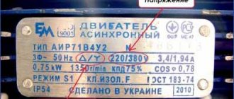
On a metal plate attached to the equipment body, manufacturers indicate the main characteristics of the engine.
It is important to know that with a star connection, the current is indicated in the denominator. It will be indicated in the numerator when connected by a triangle. The phase current is always less than the rated current by more than 1.5 times. Therefore, an important condition will be to select the wire cross-section for the motor windings and maintain the nominal value of the circuit resistance.
Provided that the outer diameter of the movable winding is more than 20 cm, winding using a two-layer method with a shorter pitch between turns is used.
The value of resistance and basic rules for operating machines
When carrying out electrical installation work, especially when using electric motors that have not been used for a long time, it is very important to check the integrity of the windings and the absence of a short interturn circuit on them.
If old and new electrical equipment is improperly stored in rooms with high levels of humidity, the insulation of the wires may become damaged and fail.
In this case, the winding resistance will decrease. Therefore, it is important to check this characteristic on each winding of the unit before turning it on, and measure the resistance between all wire terminals.
All measurement results must comply with the requirements and standards of GOST and technical specifications.
It is important to take temperature into account when taking measurements.
According to the requirements of the work regulations, the temperatures of the insulating layer and the environment must correspond to each other. In this case, the winding resistance value for equipment with low voltage should be less than 1 MOhm. For DC motor windings, the winding resistance should not exceed 5 MOhm.
How to properly measure insulation integrity
A megohmmeter is used to carry out measurements. This is a modern compact device that includes an ohmmeter and a magnetoelectric DC generator. With a rated unit voltage of 600 V, the insulation resistance of the equipment should be produced by applying a load of 500 V to it.
When working with equipment with a rating of less than 3000 V, a current of no more than 1000 V is supplied to it. In the case of measuring motor coils with a rated voltage of over 3000 V, a value of more than 2500 V is set on the megohmmeter.
When connecting the winding through a capacitor, you will need to disconnect the capacitance from the network before taking measurements.
To obtain reliable results, the following conditions must be met:
- temperature less than 50 results cannot be reliable;
- it is necessary to turn off the load on the electric motor;
- before work, it is necessary to clean the insulation from contamination;
- to remove the load, you will need to ground the equipment for a short time;
- It is necessary to carry out measurements with the arrow of the device firmly installed;
- it is necessary to connect to the winding using megohmmeter clamps;
- The measuring device must pass a control test; this must be verified before use.
Only when these conditions are met can you begin to measure resistance. In this case, the data will be reliable and you will have the opportunity to early detect breakdowns and violations of the integrity of the wiring insulation.
Do not forget to remove the residual voltage from the electric motor after taking measurements.
Source: https://www.ttaars.ru/about/stati/soprotivlenie-obmotok-elektrodvigatelya/
Safety regulations
Before checking the engine, make sure that the plug and cord of the entire device are in good working order. If electric current flows into the device, the indicator light will light up. If everything is in order with the current supply, we proceed to check the motor, which must first be removed from the unit housing. This operation can only be performed when it is completely de-energized!
It would be a good idea to check the serviceability of the multimeter. Most often, the battery charge decreases, which is why the readings may be inaccurate.
Online consultation
On the NSN 7471-75-40P compressor, the thermal relay is switched off when turned on. Write the resistance of the electric windings. engine.
07/28/2011 // Litvinov Sergey Alexandrovich
The HSN7471-75-40P compressor electric motor consists of 6 windings with a connection designated as Δ/ΔΔ .
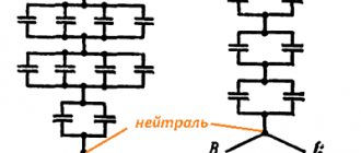
The diagram of their connection can be figuratively described as follows. Imagine an isosceles triangle, on each side of which there are two series-connected windings.
note
At the vertices of this triangle there are contact points 1 (L1), 2 (L2), 3 (L3) (clockwise) - this is PW1.
In each side of this triangle between two series-connected windings there are contact points 9 (L3), 7 (L1), 8 (L2) (clockwise from vertex 1) - this is PW2.
First, all windings are powered according to the PW1 circuit, then, after 0.5 seconds, they are additionally powered according to the PW2 circuit.
See HSN7471-75-40P compressor motor resistance table. Please note that the resistance of one winding is less than 1 ohm. To measure it correctly, a special tester is required.
26 09 2012
When turned on, the CSH 8551-110-40P compressor overheats greatly within 10 minutes. In this case, the current coincides with exactly the same, normally operating compressor. Write the resistance of the electric windings. engine.
06/27/2012 // Ivan
The following reasons can be assumed for this:
- inside the compressor, the discharge gas is bypassed from the discharge port somewhere to the suction, through, for example, a loosely closed/damaged bypass valve….
- excess oil in the compressor oil separator.
- dry rolling in bearings - little oil.
Check all functional operating parameters of the overheating compressor again. The currents are within normal limits, but what about its performance?
28 06 2012
if you remove the sensor. will the oil work?
08 08 2012 // Evgeniy
The oil won't work. Where the temperature sensor is screwed in on semi-hermetic screw compressors BITZER HS/OS series, there should be no oil.
29 08 2013
Hello. Can you give data on the resistance of the compressor windings hsk7451-70-40p.
07 04 2014 // rinat
No data, but somewhere around HSN7471-75-40P.
07 04 2014
For compressor CSH 7551-70 serial number 16240684 Write the resistance of the electrical windings. engine. Required for diagnostics.
04/23/2014 // Vyacheslav
Important
I will request from GmbH a final test certificate for this compact screw compressor manufactured in April 2002.
Just keep in mind that the resistance of its windings is less than 1 Ohm - a special device is required.
As a rule, the resistance of the windings does not change over time. During brutal operation of the compressor, the insulation resistance of the enamel wire of the windings changes due to the detrimental effect on it of motor overheating due to overloads and insufficient flow of intake cold vapors, due to the effects of oil acid, due to liquid refrigerant rapidly boiling in the engine compartment, etc. .
24 04 2014
Good afternoon. When measuring the operating currents of the electric motor of the CSH8563-125Y-40P compressor, the currents at points 1-2-3, depending on the load, were as follows. values: 1L1=50-90A, 2L2=1-10A, 3L3=50-90A.
the currents at points 7-8-9, depending on the load, were as follows. values: 7L1=50-100A, 8L2=90-180A, 9L3=50-100A.
What could cause such an accident? And how is it possible to check the integrity and insulation resistance of each of the 6 windings separately? Thank you!
How to connect
Each device model has its own output voltage value, for this reason, to effectively test the insulation or measure its resistance, the correct selection of a megohmmeter is necessary.
To check the cable insulation, it is necessary to create a case in which the energy supplied to the section is higher than the rated one, but within the limit described in the technical document. For example, if the voltage is supplied in the amount of 500, then it is necessary to slightly exceed this value.
The duration of measuring insulation resistance with a megohmmeter should usually be no more than 30 seconds. This is necessary so that defects can be accurately identified, as well as their subsequent appearance during network fluctuations.
The basis of measurement is preparation with execution and final stage. Each stage has its own manipulations that are necessary to achieve the goal.
Note! When preparing the work, you need to understand the actions, study the electrical installation in schematic form to eliminate possible breakdowns and ensure safety. When starting work, you should check the device for serviceability
Next, you need to connect the portable grounding to the earth circuit, check and ensure that the voltage is turned off in the area, install a portable type of grounding, assemble a measurement circuit, remove the incoming energy and the remaining charge. Then disconnect the connection wire
When starting work, you should check the device for serviceability. Next, you need to connect the portable grounding to the earth circuit, check and ensure that the voltage is turned off in the area, install a portable type of grounding, assemble a measurement circuit, remove the incoming energy and the remaining charge. Then disconnect the connection wire.
At the final stage, the disassembled circuits are restored, shunts and short circuits are removed, and circuits are prepared for operating mode. Later, the results of measurements of the insulation layer are documented in the insulation test report
Professional connection of a megohmmeter according to instructions
We check the engines visually
If the bearings are in good condition, holding the shaft with your hand and rocking it from side to side, you will not feel any play. At the same time, when the engine is running, there is no noise coming from the bearing. And, conversely, in a worn bearing both play and significant noise are noticeable, especially if it is a rolling bearing. For an asynchronous motor, regardless of whether it is three-phase or single-phase, the lack of normal performance is most often associated with the bearings.
In such engines these are the only parts that mechanically wear out over time. The exception is asynchronous motors with rings. They also contain synchronous electric motors. The rings and brushes sliding on them are subject to wear and, along with the bearings, are inspected to check their normal performance. The surfaces of rings that are in good and serviceable condition are smooth and free of scratches. The brushes must be ground into the surface of the rings and pressed securely against them.
Brushes: worn on the left, new on the right
Three-phase asynchronous motor with wound rotor
Electric motors with slip rings
But for most readers, the most common problems will be related to commutator motors. They are basic in all electrical appliances and power tools. And their wearing parts are also bearings and brushes. But the brushes slide not along the rings, but along the commutator. Its surface is non-uniform, which significantly accelerates the wear of the brushes, which then turn into graphite dust.
It settles on all surfaces of the engine and body of the electrical appliance, creating conditions for the appearance of electrical circuits
Therefore, when checking such electrical appliances, it is important to promptly identify a critical level of contamination with graphite dust and perform high-quality cleaning of it from both the engine itself and all other surfaces.
Collector engine
We call the commutator motor
We switch the selector to resistance. At 200 ohms. And we call the rotor and stator separately. The rated resistance of each stator winding - usually there are two - can be found in the documentation for the motor. But, if it is unknown, any value in the range from 5 to 100–150 Ohms will indicate the serviceability of the winding. The rotor or armature of a commutator motor has more windings. We call each one. We position the probes in the manifold so that they are at the maximum distance from each other. The probes seem to take the place of the engine brushes. Turn the rotor slightly until the multimeter shows a slight resistance. We continue to rotate the shaft until contact is lost and then restored. So we check all the windings. Then we move the tester selector to the resistance sector, setting the limit to 2000 KOhm and check for leakage. Without touching any engine parts or bare probes with bare hands, we measure the resistance between the stator winding and the housing. The device should show one. The rotor is checked in the same way. Each winding and housing are closed. If the device shows a value different from one, action must be taken. Take care of yourself, follow the safety rules.
On what principle does it work?
- The current generates a pulsed magnetic field in the static part of the motor. The magnetic field can be considered as two separate ones with the same amplitudes and frequencies.
- If the rotor is motionless, the moments appearing due to the action of the field are equal to zero, although multidirectional.
- If the rotor begins to move, the corresponding torque will begin to prevail. This will prevent the element from moving in the other direction.
- If the necessary mechanisms for starting the rotor are missing, it will not be able to start, which leads to the occurrence of zero torques.
The start is carried out by a magnetic field formed due to the presence of two windings in the stator: working and starting. The starting volume is less than the working volume. The additional winding is connected to the network, usually through a capacitor. It turns on only when the engine starts. If the motor has little power, the starting phase in it is probably short-circuited.
Start pressure
The motor starts with a button that must be held for 2-3 seconds. At this time, the engine accelerates to its normal speed. When the key is released, the starting winding is turned off. The motor switches to single-phase operation.
If you press the start button for more than three seconds, the winding insulation may overheat or even catch fire. This, of course, will lead to breakdown of the unit, and a fire can pose a threat to the health and lives of people. A longer time under load can cause overheating, insulation fire and device malfunction.
To increase the reliability of the machine, a centrifugal switch and a thermal relay are mounted in its body. The first mechanism is needed to automatically turn off the starting winding when the rotor reaches the desired speed. The second mechanism is used to turn off overheated windings.
Mechanism of operation
For the device to work normally, it must be connected to a single-phase network with a voltage of 220V. That is, there will be enough sockets in any apartment. That's why it became so popular. A single-phase motor is used in literally all of our household electrical appliances.
All electric motors of this type can be divided into two more subtypes:
- In the first case, the auxiliary winding operates through the starting capacitor only when the drive starts. When the unit reaches the desired rotation speed, it turns off.
- The second subtype of machines contains a working capacitor, this was mentioned above. In this situation, the starting winding continues to work along with the starting engine.
The capacitor also requires a resistance check. You can carry out the procedure with a multimeter.
Checking the capacitor with a multimeter
Electronic megohmmeter
It is clear that when checking resistance, the ohmmeter has no equal. It gives the most accurate measurement results. This allows the integrity of the dielectric to be assessed. After all, the performance of the machine depends on it no less than on the serviceability of the windings.
If you're doing a home inspection, you don't need exact values. The main thing here is to find (or not find) a breakdown. The multimeter does this very well.
Measurements are carried out as follows:
- turn the multimeter into ohmmeter mode;
- set the maximum value - infinite;
- measure the capacitance resistance value at the terminals.
Multimeter operation in ohmmeter mode
The following results are possible:
- Resistance is less than infinity. The device is faulty. The electrolyte may have leaked or the dielectric may be broken.
- At first, a slight deviation of the arrow is noticeable, but it returned to its place. The capacitor is functioning properly.
- The tester's needle is fixed on one of the values. This also indicates a breakdown in the device.
Any drive can be removed from one electric motor and connected to another. As an example, the engine from a refrigerator (if it is working) will function perfectly in a lawn mower.
Types of devices to check
In addition to the standard set of tools (pliers, a set of screwdrivers and wrenches), you will need an electrical device that performs the “diagnosis test” of the motor.
Multimeter
Previously, a multimeter was called an avometer - it was a pointer device that measured resistance, voltage and current. Today, pointer instruments have almost completely disappeared from the market - with the exception of miniature, modern versions, which are difficult to find. They have given way to digital counterparts that allow you to check diodes, capacitors, inductors and windings, and even the health of transistors.
Tester
The same as a multimeter, but can be made independently - from any pointer galvanometer. To carry out measurements, the tester switches to the resistance measurement mode (values on the sector with the designations Ohm and kOhm).
Checking other parts and other potential problems
- oil leak from the condenser;
- presence of holes in the body;
- swollen capacitor housing;
- unpleasant odors.
The capacitor is also checked using an ohmmeter. The probes should touch the terminals of the capacitor, and the resistance level should be small at first, and then gradually increase as the capacitor is charged with voltage from the batteries. If the resistance does not increase or the capacitor is short-circuited, then most likely it is time to change it.
Before re-testing, the capacitor must be discharged.
We move on to the next stage of checking the engine: the rear part of the crankcase, where the bearings are installed. At this point, a series of electric motors are equipped with centrifugal switches that switch starting capacitors or circuits to determine the number of revolutions per minute. You also need to check the relay contacts for burnt marks. In addition, they should be cleaned of grease and dirt. The switch mechanism is checked using a screwdriver; the spring should work normally and freely.
And the final stage is checking the fan. We will look at this using the example of testing a TEFC engine fan, which is completely enclosed and air-cooled.
Make sure the fan is securely attached and not clogged with dirt or other debris. The holes on the metal grill must be sufficient for free air circulation; if this is not ensured, the engine may overheat and subsequently fail.
Causes of malfunction and characteristic symptoms
The main factors that influence stator failure are the following:
- the supply network does not always guarantee a stable voltage; surges are possible;
- during operation of the power tool, some liquid, for example water, may get inside the stator;
- when processing some materials (concrete, wood and others), a large amount of dust is formed, from which it is difficult to protect against getting on the stator winding;
- long-term use of an angle grinder under overload conditions, which causes overheating of the power tool;
- While the grinder is operating, you should not stop it by abruptly pulling the cord out of the outlet.
408-105 Stator for Hitachi G18SE3 and HAMMER angle grinders. Photo 220Volt
Typical signs of a stator malfunction are the following:
- there is a persistent smell of burnt insulation of the winding wires;
- the temperature of the body parts of the angle grinder increases noticeably;
- The electric drive of the angle grinder hums more than under normal conditions;
- the appearance of smoke is quite possible;
- the spindle begins to rotate more slowly, or may even stop completely;
- the opposite extreme to the previous case is possible - the spindle begins to spontaneously work at increased speeds and goes into overdrive.
Features of testing electric motors with additional elements
Electric powertrains are often equipped with additional components designed to protect the equipment or optimize its performance. The most common elements built into the motor are:
- Thermal fuses. They are set to operate at a certain temperature in such a way as to avoid burning and destruction of the insulating material. The fuse is retracted under the insulation of the windings or fixed to the body of the electric motor with a steel shackle. In the first case, access to the pins is not difficult, and they can be checked without problems using a tester. You can also use a multimeter or a simple indicator screwdriver to determine which detachable legs the protective circuit goes to. If the temperature fuse is in normal condition, it should indicate a short circuit when measured.
- Thermal fuses can be successfully replaced by temperature relays, which can be either normally open or closed (the second type is more common). The brand of the element is affixed to its body. Relays for various types of engines are selected in accordance with technical parameters, which can be found by reading operational documents or finding the necessary information on the Internet.
- Engine speed sensors with three outputs. They are usually equipped with washing machine motors. The basis of the operating principle of these elements is a change in the potential difference in the plate through which a weak current passes. Power is supplied through the two outer terminals, which have low resistance and should show a short circuit when tested. The third pin is checked only in operating mode, when it is acted upon by a magnetic field. Do not measure the sensor power supply when the engine is running. It is best to remove the power unit altogether and apply current separately to the sensor. To generate pulses at the sensor output, rotate the axis. If the rotor is not equipped with a permanent magnet, you will have to install it during the test, having first removed the sensor.
A regular multimeter is usually sufficient to diagnose most problems that may occur in electric motors. If it is not possible to determine the cause of the malfunction with this device, the test is carried out using high-precision and expensive devices that are available only to specialists.
This material contains all the necessary information on how to properly test an electric motor with a multimeter at home. When any electrical equipment fails, the most important thing is to ring the motor winding to eliminate its malfunction, since the power plant has the highest cost compared to other elements.
Checking other parts and other potential problems
You should definitely check the starting capacitor, which is needed to start some electric motor models. Basically these capacitors are equipped with a protective metal cover inside the motor. To check the capacitor you need to remove it. Such an inspection may reveal signs of problems such as:
- oil leak from the condenser;
- presence of holes in the body;
- swollen capacitor housing;
- unpleasant odors.
The capacitor is also checked using an ohmmeter. The probes should touch the terminals of the capacitor, and the resistance level should be small at first, and then gradually increase as the capacitor is charged with voltage from the batteries. If the resistance does not increase or the capacitor is short-circuited, then most likely it is time to change it.
Before re-testing, the capacitor must be discharged.
We move on to the next stage of engine testing: the rear part of the crankcase, where the bearings are installed. At this point, a number of electric motors are equipped with centrifugal switches. which switch start capacitors or circuits to determine the number of revolutions per minute. You also need to check the relay contacts for burnt marks. In addition, they should be cleaned of grease and dirt. The switch mechanism is checked with a screwdriver; the spring should work normally and freely.
And the final stage is checking the fan. We will look at this using the example of testing a TEFC engine fan, which is completely enclosed and air-cooled.
Make sure the fan is securely attached and not clogged with dirt or other debris. The holes on the metal grill must be sufficient for free air circulation; if this is not ensured, the engine may overheat and subsequently fail.