Current transformers for electric meters - characteristics and connection options
When operating energy systems of various types, situations often arise that require converting electrical quantities into analogues with certain ratios.
Current transformers for electric meters can significantly expand the standard measurement limits of metering devices.
Current transformer rated voltage
One of the main parameters related to current transformers for electric meters is the rated voltage level, which is indicated in the passport for the device. Voltage ratings range from 0.66kW to 1150kW:
- 0.66 kW;
- 6.0 kW;
- 10 kW;
- 15 kW;
- 20 kW;
- 24 kW;
- 27 kW;
- 35 kW;
- 110 kW;
- 150 kW;
- 220 kW;
- 330 kW;
- 500 kW;
- 750 kW;
- 1150 kW.
The rated values of the primary current level on an electrical circuit indicate the current indicators on the primary transformer winding.
The secondary rated current parameters are the standard values on the secondary type winding. The determination of such current flows is carried out based on the nominal values of power and voltage.
In this case, the primary type of winding is connected to a source of electrical energy, and the secondary winding is closed to measuring or protective type devices with low internal resistance.
The current parameters of the rated or line voltage, under the conditions under which the instrument current transformer remains operational, must be indicated in the accompanying documentation and reflected in the table for the device.
Accuracy class
With the correct choice of current transformer device, the consumer has a real opportunity to connect measuring and protective devices to high-voltage electrical lines. The accuracy class level is one of the most important characteristics indicating the measurement error, which should not be higher than the parameters according to regulatory documents.
The accuracy class is determined by several main factors, including current and angle errors, as well as relative total error indicators. The first two concepts are always characterized by magnetizing current.
Operating principle of current transformer
Industrial devices use several accuracy classes:
In accordance with the GOST currently in force in our country, the accuracy class should be focused on current errors, therefore for indicators of ±40′ class 0.5 is assumed, and for ±80′ – class 1.0. It should be noted that classes 3.0 and 10P are not standardized according to existing rules.
note
The presence of the letter “S” in the marking indicates an accuracy class within the range of 0.01-1.2.
Class 10P is used in protective circuits, and standardization is carried out in accordance with the relative total error of no more than ten percent.
The use of devices with an accuracy class of 1.0 is allowed, but only if the electric meter has an accuracy class of two units.
The measuring and information system, represented by devices that receive, process and transmit data, as well as metering devices, is capable of generating correct indicators only with high accuracy of current transformers.
For commercial accounting, the accuracy class level should be 0.5S, and for technical accounting – 1.0S.
Rated secondary current
The structure of the secondary winding of current transformers, which are designed for voltages of no more than a thousand volts, has some differences. At least two secondary windings are installed on a high-voltage device.
The principle of their operation is similar to the functioning of a step-up transformer. Regardless of the power level of the primary winding, the current rating on the secondary winding is usually stable at 5A.
Current transformer design
The rated values of the secondary current “I2n” are indicated in the table attached to the device passport. The rated currents on the secondary winding are equal to unity or 5A, but the second indicators are allowed only in devices with primary currents not exceeding 4000A.
However, it is also possible to manufacture modern current transformer devices on individual orders with secondary current ratings of 2.0A or 2.5A.
Rated primary current
Depending on the design features of the primary winding, current transformers can be not only multi-turn, but also single-turn and busbar.
Today, the second version of the device is most widespread.
Single-turn models of current transformers are represented by varieties that do not have an individual primary winding or with an individual primary winding.
Single-turn models without their own primary winding are characterized by a built-in, busbar or detachable design. The primary current level, in this case, is always determined in accordance with the standardized rated currents.
Rated currents of the primary type “I1н” are indicated in the passport tabular data of the transformer device, and determine the standard transformation ratios in the form of the ratio of the rated current indicators on two types of windings of the device.
It is necessary to select the transformation ratio in strict accordance with the design load, as well as with mandatory consideration of the possibility of functioning of the installed device in emergency situations. The current rating on the primary winding cannot be less than the maximum operating current values of the operated electrical installation: I2nom.tt>Imax.eu.
It is allowed to use devices that have overestimated coefficient values, provided that the maximum load level of the current connection on the secondary winding is 40% or more of the rated current of the electric meter. Minimum workload requirements are 5% or more.
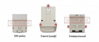
Connection diagram
Let's look at how to connect a current transformer. Depending on the design features of the current transformer for electric meters, there are several types of such devices:
- current transformers intended for outdoor installation in outdoor switchgear;
- current transformers intended for closed installation of distribution devices;
- built-in current transformers;
- current transformers intended for installation on bushing-type insulators;
- current transformers in portable or mobile design.
Current transformers provide complete insulation of the operated power electrical circuits. A measuring device in everyday life is a guarantee of safe operation, so experts recommend using the so-called galvanic isolation. The disadvantages of this installation method include a fairly large number of electrical wires.
The connection of the electric energy meter through current transformers is carried out using ten-core cables. The design uses separate circuits for both current and voltage. The standard installation diagram requires the mandatory connection of three elements of the electric meter in compliance with the polarity rules with direct phase rotation relative to “U”.
Electric meter connection diagram via current transformers
In the process of self-installation of electrical energy measuring instruments, current transformers are connected to circuit breaks using special, very easy-to-use clamps “L-1” and “L-2”.
Video on the topic
Source: https://proprovoda.ru/elektrooborudovanie/transformatory/toka-dlya-elektroschetchikov.html
Selection of voltage transformers
Voltage transformers designed to power the voltage coils of measuring instruments and relays are installed on each section of the busbars. They are selected according to their design, design and connection diagram of the windings, rated voltage, accuracy class and secondary load.
Conditions for choosing voltage transformers
- design, connection diagram;
- compliance with the condition Uc.nom = U1nom (where Uc.nom is the rated voltage of the network to which the voltage transformer is connected, kV;
- U1.nom—rated voltage of the primary winding of the transformer, kV);
- accuracy class;
- compliance with condition S2 races
- S2 nom - rated power of the secondary circuit of the voltage transformer, ensuring its operation in a given accuracy class, V*A).
For single-phase transformers connected in a star, as U it is necessary to take the total power of all three phases, and for those connected according to an incomplete open triangle - twice the power of one transformer. In the selected accuracy class, if the load (secondary) exceeds the rated power, some of the devices are connected to an additionally installed voltage transformer. The secondary load of a VT is the power of the instruments and relays connected to the VT.
To simplify calculations, the design load can not be divided into phases, then
When determining the secondary load, the resistance of the connecting wires is not taken into account, since it is small. However, the PUE requires an assessment of the voltage loss, which in wires from transformers to meters should not exceed 0.5%, and in wires to panel measuring instruments - 3%. The wire cross-section selected for mechanical strength, as a rule, meets the requirements for voltage loss.
The choice of voltage transformer type is determined by its purpose. If metering meters receive power from the transformer voltage, then it is advisable to use two single-phase transformers of the NOM or NOL type at voltages of 6, 10, 35 kV, connected according to an open incomplete triangle.
Two single-phase VTs have more power than one three-phase one, and in terms of cost for voltages of 6 and 10 kV they are approximately equal. If, simultaneously with the measurement, it is necessary to monitor the insulation in 6-10 kV networks, then install three-phase three-winding five-rod voltage transformers of the NTMI series or a group of three single-phase transformers of the ZNOM or ZNUT series, if the power of the NTMI is insufficient.
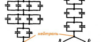
When using three single-phase transformers connected in a star, the neutral point of the high voltage winding of the VT must be grounded for proper operation of the insulation monitoring devices
For voltages of 110 kV and above, NKF cascade transformers are used.
It's simple about counters
Good day, dear readers!
I haven't written anything for a long time. There's a reason for this. I'm doing renovations.
I wanted to make a few videos about installing wiring in an apartment, but I realized that it was not entirely interesting.
Therefore, today’s article is about electricity meters.
I threw out the pretentious and boring version of it and decided to write it as if I were telling it to an ordinary citizen, for example you, who knows nothing about meters.
Once upon a time, in my list of laboratory works there was a type of work: checking and adjusting accounting circuits. There was even a technique. And in electrical networks, the service for monitoring electricity metering was generally part of the laboratory, at least here in Ryazan...
Features of choice
When choosing a current transformer, you must be guided by the basic parameters:
- Mains voltage rating. The nominal value must be greater than or equal to the operating voltage.
- Primary and secondary winding current. The first indicator depends on the transformation ratio, the second depends on which meter it is.
- Conversion factor. It is selected according to the load in emergency cases, but the PUE establishes the need to install devices with a coefficient greater than the nominal one.
- Accuracy class. Depends on the intended use of the meter. In a commercial enterprise, 0.5S devices are justified, in a private home - 1S.
The design is determined by the type of meter. For models up to 18 kV, a single-phase or three-phase device is suitable. If the value is greater than 18 kV, a single-phase transformer is used.
Selection of a current transformer for organizing relay protection
The relay current transformer has an accuracy class of 10P and 5P. The PUE states that its error should not be more than 10% in current and 7 degrees in angle. If the error is exceeded, additional equipment is installed.
Under normal conditions, the transformer relay detects the type of fault (low voltage, over/under current or frequency). After measuring parameters and detecting deviations, protection is activated - the network is de-energized.
Nuances of choosing devices for the metering chain
To ensure correct measurements, you can connect devices with an accuracy class of no more than 0.5(S) to the metering circuit. In the presence of fluctuations and accidents, the current and voltage flow graphs may be incorrect. Failure to comply with the accuracy class may lead to overestimation of the meter readings.
In clause 1.5.17 of the PUE it is established that if the coefficient is too high, the transformer for the metering circuit must have a secondary current:
- at maximum load – no more than 40%;
- at minimum load – no more than 5%;
- accuracy class – from 25 to 100% of the nominal value.
The CT power coefficient ranges from 1 to 5% of the primary.
Pre-selection table for current transformer by power and current
It is advisable to make a tabular selection of equipment after clarifying the technical parameters of the device. If they are known, it is worth choosing a CT according to the table, which shows the power, load and transformation ratio.
| Maximum power when calculated, kVA | 380 V network | |
| Load, A | Transformation coefficient, A | |
| 10 | 16 | 20/5 |
| 15 | 23 | 30/5 |
| 20 | 30 | 30/5 |
| 25 | 38 | 40/5 |
| 35 | 53 | 50/5 or 75/5 |
| 40 | 61 | 75/5 |
| 50 | 77 | 75/5 or 100/5 |
For a network with a voltage of 1.5 kV, a similar table is used.
| Maximum power when calculated, kVA | 1.5 kV network | |
| Load, A | Transformation coefficient, A | |
| 100 | 6 | 10/5 |
| 160 | 9 | 10/5 |
| 180 | 10 | 10/5 or 15/5 |
| 240 | 13 | 15/5 |
When using the tabular method, it must be taken into account that the secondary current of the device should not be more than 110% of the nominal value.
Replacing electric meters – Electrics – Some tips
Home / Some tips / Electrics / Replacing electric meters
An electric meter is a device that keeps track of electricity consumed at home and in industrial enterprises. Today the market offers a wide selection of different counters, in order to choose the right one, you need to understand what they are.
Meters are divided by type of operation into induction and electronic. Induction meters are a cheaper option, while electronic ones are more reliable and accurate. There are also single-phase and three-phase meters for various networks.
The accuracy class of electricity meters is divided from 0.2 to 2.5. This figure shows the level of instrument error. Not long ago, a new GOST was introduced, according to which devices with an accuracy class of at least 2 percent can be used in everyday life.
note
Whereas previously a measurement error of 2.5 was allowed. Depending on the connection, electricity meters can be directly connected or connected via transformers. If the total load does not exceed 100 amperes, a direct connection meter can be used.
For larger loads, it should be connected via a current transformer.
There are 2 voltage classes: 220/380 V and 100 V.
There are single-tariff, double-tariff and multi-tariff models. Two-tariff devices allow you to take into account the amount of energy spent separately during the day and at night. The use of such devices helps to significantly save money. After all, the cost of energy differs by almost 2 times at different times of the day.
Accuracy class
The accuracy class of a current transformer is specified in GOST 7746-2001 and depends on its purpose, as well as the parameters of the primary current and secondary load:
- Under conditions of low resistance, almost complete shunting of the magnetized branch occurs. The device operates with a large error.
- As the resistance increases, the error also increases. The reason is the operation of the device in the saturation region.
- At the minimum primary current rating, the transformer operates in the lower part of the magnetized curve, at the maximum, at the saturation section.
The exact selection of a transformer by accuracy class can be made based on the table.
| Accuracy class | Primary current rating in % | Secondary load limit in % |
| 0,1 | 5, 20, 100-200 | 25-100 |
| 0,2 | ||
| 0.2S | 1,5, 20, 100, 120 | |
| 0,5 | 5, 20, 100, 120 | |
| 0.5S | 1, 5, 20, 100, 120 | |
| 1 | 5, 20, 100-120 | |
| 3 | 50-120 | 50-100 |
| 5 | ||
| 10 |
For protection devices, the accuracy class is also determined from the table.
| Accuracy class | Maximum error | Percentage of maximum secondary load | ||
| thermal | corner | |||
| min | Wed | |||
| 5P | ±1 | ±60 | ±1,8 | 5 |
| 10R | ±3 | There is no norm | 10 | |
For energy metering, models with an accuracy class of 0.2S - 0.5 are used, for ammeters with minimal sensitivity - with 1st or 3rd, for relay protection - 5P and 10P.
How to connect an electric meter through current transformers?
There are several schemes for such connection. Let's analyze all these schemes in relation to the three-phase connection option. What are electricity meters for? In general, meters are needed to take into account the electrical energy consumed in three- and four-wire networks with a current frequency of 50 hertz. Three-phase meters are of the following types:
- 3*57.7/100 V;
- 3*230/400 V.
Such meters must be connected to a source of electricity using measuring current transformers designed for a secondary current of 5 A and voltage transformers with a secondary voltage of 100 V.
The circuits discussed here are applicable to any type of meters (both induction-type devices and electronic ones).
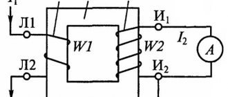
The first thing to remember when making a connection is that when connecting, it is necessary to observe the polarity of the connection of the windings (L1, L2 - primary; I1, I2 - secondary) of the current transformers. The polarity of the windings of voltage transformers is also subject to mandatory rechecking. The transformers themselves also need to be chosen correctly.
About the principles of connection using current transformers
Let's start looking at connection diagrams with meters that have semi-indirect connection. There are several such schemes.
Ten-wire
In this circuit, the power circuits are separated by current and voltage, which is a significant advantage for reasons of electrical safety.
The negative side of this scheme is that you need a lot of wires to connect.
Now let's look at the purpose of the existing clamps:
- Input wire clamp for phase A;
- Clamp of the input wire of the measuring winding of phase A;
- Output wire clamp for phase A;
- Phase B input wire clamp;
- Clamp of the input wire of the measuring winding of phase B;
- Output wire clamp for phase B;
- Input wire clamp for phase C;
- Clamp of the input wire of the measuring winding phase C;
- Output wire clamp for phase C;
- Input neutral wire clamp;
- Neutral wire clamp.
Current transformer contacts:
- L1 – phase (power) line input contact;
- L2 – phase line output contact (load);
- I1 – measurement winding input contact;
- I2 – measurement winding output contact.
Here is a description of the diagram of such a connection.
Current transformers must be connected to the phase wires with terminals L1 and L2.
Phase A is connected to terminal L1 of current transformer TT1, and terminal 2 of the meter is also connected there. Terminal 1 is connected to pin I1 of CT1.
Contacts I2 of current transformers TT1 and TT2 must be connected together, contacts 6 and 10 of the meter are connected to the same point, after which all this must be connected to the neutral.
Contacts L2 of all CTs are connected to the load. Now let's look at connecting the remaining contacts:
- Contact 3 of the meter is connected to I2 TT1;
- Contact 4 of the counter – I1 TT2;
- Contact 5 of the counter – phase B input and terminal L1 of TT2;
- Contact 7 of the counter – terminal I1 TT3;
- Contact 8 of the counter – phase C input and terminal L1 of TT3;
- Contact 9 of the counter – terminal I2 TT3.
Connecting current transformers in a star configuration
In such a scheme, fewer wires are needed to make the connection. In this circuit, terminals I2 of all current transformers, connected together, are connected to terminal 11 of the meter. Contacts 3, 6, 9 and 10, connected together, are connected to the neutral wire. We connect the remaining terminals in the same way as in the previous version.
Connection diagram using test terminal box
There is a special requirement for connecting electricity meters through transformers (PUE, Chapter 1.5, Section 1.5.23), which means that this connection must be made using a test block (box).
Commercial metering of electrical energy
Technical requirements for the installation of measuring systems
commercial electricity metering
Requirements for estimated electricity meters
Metering devices are a set of devices that provide measurement and metering of electricity (current and voltage measuring transformers, electrical energy meters, telemetric sensors, information and measuring systems and their communication lines) and are interconnected according to an established scheme.
Electric energy meter is an electrical measuring device designed to account for consumed electricity, alternating or direct current. The unit of measurement is kWh or Ah.
Electric energy meter is an electric energy meter designed for commercial settlements between market entities.
To account for electrical energy, electricity meters are used, the types of which are approved by the federal executive body for technical regulation and metrology and are included in the state register of measuring instruments.
Technical parameters and metrological characteristics of electric energy meters must meet the requirements:
GOST 52320-2005 Part 11 “Electric energy meters”; GOST R 52323-2005 Part 22 “Static active energy meters of accuracy classes 0.2S and 0.5S”; GOST R 52322-2005 Part 21 “Static active energy meters of accuracy classes 1 and 2”;
GOST R 52425−2005 “Static reactive energy meters”.
It is recommended to install meters for calculating the energy supply organization with electricity consumers at the boundary between the network (by balance sheet) of the network organization and the consumer.
If the calculated metering device is not located on the border of the balance sheet of electric networks, the volume of electrical energy received into the electric networks (released from electric networks) is adjusted taking into account the amount of standard losses of electrical energy that occur in the section of the network from the border of the balance sheet of electric networks to the location installation of a metering device, unless a different adjustment procedure is established by agreement of the parties.
Meters should be located in dry rooms that are easily accessible for maintenance, in a place that is sufficiently free and not cramped for work. General industrial meters are not allowed to be installed in rooms where, due to production conditions, the temperature can often exceed +40°C, as well as in rooms with aggressive environments. It is allowed to place meters in unheated rooms and corridors of switchgears of power plants and substations, as well as in outdoor cabinets. If the devices are not intended for use in conditions of negative temperatures, they must be permanently insulated for the winter using insulating cabinets, hoods with heated air inside them with an electric lamp or heating element to ensure a positive temperature inside the hood, but not higher than +20 °C.
Meters must be installed in cabinets, chambers of complete switchgears (KRU, KRUN), on panels, switchboards, in niches, on walls with a rigid structure. The height from the floor to the meter terminal box should be within 0.8-1.7 m. A height of less than 0.8 m is allowed, but not less than 0.4 m.
In places where there is a danger of mechanical damage to meters or their contamination, or in places accessible to unauthorized persons (passages, staircases, etc.), a locked cabinet with a window at dial level should be provided for meters. Similar cabinets should also be installed to co-locate meters and current transformers when performing metering on the low voltage side (at the consumer input).
The designs and dimensions of cabinets, niches, panels, etc. should provide convenient access to the terminals of meters and current transformers. In addition, it must be possible to conveniently replace the meter. The design of its fastening must ensure the possibility of installing and removing the meter from the front side.
If there are several connections at the facility with separate electricity metering, the meter panels must contain inscriptions with the names of the connections.
At 0.4 kV connections with a load up to 100 A inclusive, use direct-connection electricity meters.
For three-phase input, use three-element electricity meters.
Newly installed three-phase meters must have state verification seals no more than 12 months old, and single-phase meters must have state verification seals no more than 2 years old. The presence of a valid verification of the electricity meter is confirmed by providing a supporting document - a passport form for the electricity meter or a verification certificate. The documents for the electricity meter must contain notes about the settings of the tariff schedule and local time.
The main technical parameter of an electricity meter is the “accuracy class,” which indicates the level of measurement error of the meter. In accordance with the section “Rules for organizing electricity metering in retail markets” of the “Basic provisions for the functioning of retail electricity markets”, approved by Decree of the Government of the Russian Federation dated May 4, 2012 No. 442, the requirements for settlement electricity meters, depending on the category of consumers, should be as follows :
| Consumer category | Accuracy class | Additional requirements |
| To account for electrical energy consumed by consumers with a maximum power of at least 670 kW | 0.5S and higher | Metering devices must be able to measure hourly volumes of electrical energy consumption and provide storage of data on hourly volumes of electrical energy consumption for the last 90 days or more or be included in the metering system |
| To account for electrical energy at the interface between electrical grid facilities and in-house engineering systems of an apartment building, the connection of which to the electrical grid facilities is carried out after the entry into force of the “Basic provisions for the functioning of retail electricity markets”, approved by Decree of the Government of the Russian Federation dated May 4, 2012 No. 442 | 1,0 and higher | |
| To account for electrical energy consumed by consumers with maximum power less than 670 kW and voltage at points of connection to electrical grid facilities of 35 kV and below (10 kV, 6 kV, 380 V, 220 V) | ||
| To account for electrical energy consumed by citizens | 2,0 and higher | |
| To account for electrical energy at the interface between electrical grid facilities and in-house engineering systems of an apartment building |
Requirements for instrument transformers
According to the technical requirements, measuring current transformers must comply with GOST 7746-2001 (“Current transformers. General technical conditions”).
Instrument voltage transformers according to their technical characteristics must comply with GOST 1983-2001 (“Voltage transformers. General technical conditions”).
The accuracy class of current transformers and the voltage for connecting calculated electricity meters must be no more than 0.5.
It is allowed to use current transformers with an increased transformation ratio (according to the conditions of electrodynamic and thermal resistance or busbar protection), if at the maximum load of the connection the current in the secondary winding of the current transformer is at least 40% of the rated current of the meter, and at a minimum operating load - at least 5 %.
The connection of the current windings of the meters to the secondary windings of the current transformers should be carried out separately from the protection circuits.
The use of intermediate current transformers to switch on metering meters is prohibited.
When connecting the meter semi-indirectly, it is necessary to install current transformers in all phases.
Current transformers used to connect meters at voltages up to 0.4 kV must be installed after switching devices in the direction of power flow.
The terminals of the secondary measuring windings of current transformers must be isolated from the terminals without control shorting or circuit breakage, using sealed covers and screens.
To ensure the safety of work carried out in the circuits of measuring instruments, relay protection devices and electrical automation, the secondary circuits (windings) of measuring current transformers must have permanent grounding.
Grounding in the secondary circuits of current transformers should be provided at the terminals of the current transformers.
The current transformer must have a valid primary (factory) or periodic verification (in accordance with the verification interval specified in the description of the type of this measuring instrument). The presence of a valid verification is confirmed by providing original passports or certificates of verification of current transformers with verification protocols.
For three-phase input, use three-phase voltage transformers or groups of single-phase voltage transformers.
To protect the measuring circuits, it must be possible to seal the grilles and doors of the chambers where fuses are installed on the high and low voltage side of the voltage transformers, as well as the drive handles of the voltage transformer disconnectors. If it is impossible to seal the chambers, the terminals of the voltage transformers are sealed.
To ensure the safety of work carried out in the circuits of measuring instruments, relay protection devices and electrical automation, the secondary circuits (windings) of voltage measuring transformers must have permanent grounding.
The secondary windings of the voltage transformer must be grounded by connecting the neutral point or one of the ends of the winding to a grounding device. Grounding of the secondary windings of a voltage transformer must be carried out, as a rule, at the terminal assembly closest to the voltage transformer or at the terminals of the voltage transformer.
The voltage transformer must have a valid primary (factory) or periodic verification (in accordance with the verification interval specified in the description of the type of this measuring instrument). The presence of a valid verification is confirmed by providing original passports or certificates of verification of the voltage transformer with verification protocols.
Requirements for measuring circuits
The presence of rations in the electrical wiring to the settlement meters is not allowed.
Installation of direct and alternating current circuits within switchboard devices (panels, consoles, cabinets, boxes, etc.), as well as internal connection diagrams of drives of switches, disconnectors and other devices, according to the conditions of mechanical strength, must be made with wires or cables with copper conductors . The use of wires and cables with aluminum conductors for internal installation of switchboard devices is not allowed.
To protect the measuring circuits, it must be possible to seal intermediate terminal blocks, test blocks, boxes and other devices included in the measuring circuits of electricity meters, while the use of such devices must be minimized.
When connecting the meter semi-indirectly, connect the conductors of the voltage circuits to the busbars using a separate technological bolt connection, in close proximity to the current transformer of this measuring complex. The places where the meter voltage circuits are connected to current-carrying parts of the network must be isolated from without controlled disconnection.
The load of the secondary windings of the instrument transformers to which the meters are connected should not exceed the rated values.
The cross-section and length of wires and cables in the voltage circuits of the calculated meters must be selected such that the voltage loss in these circuits is no more than 0.25% of the rated voltage.
For an indirect meter connection scheme, the secondary circuits should be routed to independent terminal assemblies or sections in a common row of terminals. If clamp assemblies are not available, test blocks must be installed. The clamps must ensure short-circuiting of the secondary circuits of current transformers, disconnecting the meter's current circuits and voltage circuits in each phase of the meters when replacing or checking them, as well as turning on the model meter without disconnecting wires and cables. The design of assemblies and terminal boxes for metering meters must ensure the possibility of sealing them.
When connecting the meter semi-indirectly, VVG cable 3 x 2.5 mm2 with insulation of cores of different colors should be used as a conductor of secondary circuits to current transformers.
Requirements for input devices and switching devices at the input
It must be possible to carry out a complete visual inspection from stationary sites of input devices, overhead lines, cable lines, as well as input equipment to metering electrical wiring to identify electrical receivers before metering connection. Places of possible connection before metering must be isolated by sealing chambers, cells, cabinets, etc.
For loads up to 100 A inclusive, avoid installing switches before the installation site of the metering unit.
For safe installation and replacement of meters in networks with voltages up to 380 V, it must be possible to turn off the meter by switching devices or fuses installed before it at a distance of no more than 10 m. Voltage relief must be provided from all phases connected to the meter.
Installation of equipment for automatic transfer of reserve, security and fire alarms and other automatic equipment should be provided after the installation site of the metering unit.
Connection diagrams for electric meters
The connection diagrams for electricity meters presented below are typical and may differ depending on the manufacturer and installation location. When installing electricity meters, you must be guided by the manufacturer's passport for this product.
Connection diagram for a single-phase electricity meter
Connection diagram for a three-phase electricity meter (direct connection)
Connection diagram for an electricity meter to a three-phase three-wire or four-wire network using 3 current transformers (semi-indirect connection)
Diagram for connecting an electricity meter to a three-phase three-wire or four-wire network using 3 current transformers and 3 voltage transformers
(indirect connection)