Defects in electric motor windings
Loss of one of the phases of the circuit (Star)
Loss of one of the phases of the circuit (Star)
Loss of one of the phases of the circuit (Triangle)
Loss of one of the phases of the circuit (Triangle)
Phase-to-phase fault
Phase-to-phase fault
Interturn closure
Interturn closure
Short circuit to the housing at the exit from the groove
Short circuit to the housing at the exit from the groove
Short circuit to the groove body
Short circuit to the groove body
Short circuit in the circuit
Short circuit in the circuit
Phase damage due to voltage imbalance
Phase damage due to voltage imbalance
Winding damage due to overload
Winding damage due to overload
Winding damage due to jammed rotor
Winding damage due to jammed rotor
Reasons for failure of electric motors
- Power quality
1.1. Transient voltage 1.2. Voltage imbalance 1.3. Harmonic distortion
- Variable Frequency Drives
2.1. Reflections of PWM signals at the drive output 2.2. Sigma current 2.3. Overloads during operation
- Mechanical
3.1. Electric motor misalignment 3.2. Shaft imbalance 3.3. Shaft play 3.4. Bearing wear
Power quality
1.1 Transients
Transient voltages and currents can arise from various sources located both inside and outside the installation. The switching on and off of adjacent loads, the operation of power factor correction capacitor banks, and even weather conditions can create transients in distribution networks. Such phenomena, differing in amplitude and frequency, can lead to destruction or breakdown of the insulation of the electric motor windings.
Locating the source of such interference can be difficult due to its rare occurrence and varied manifestations. For example, transients can occur in control circuits. This may not necessarily damage the equipment directly, but may interfere with its operation.
Transient processes can arise from various sources located both inside and outside the installation
| Impact: | Breakdown of the insulation of the electric motor winding leads to its early failure and unplanned downtime |
| Measurement and diagnostic tool: | Three-Phase Power Quality Analyzer |
| Criticality: | High |
1.2 Voltage imbalance
Three-phase distribution networks are also used to supply power to single-phase loads. Imbalance in impedance or load distribution can contribute to unbalance of all three phases. Potential faults can occur in the motor lead cables, in the cable terminations on the motor, and possibly in the windings themselves. Such an imbalance can lead to overvoltages in the phase circuits of a three-phase power system. At the simplest level, the voltages of all three phases should always be the same value.
Voltage imbalance in impedance or load distribution can contribute to imbalance of all three phases
| Impact: | The imbalance creates excessive current in one or more phases, leading to increased operating temperatures and subsequent insulation breakdown. |
| Measurement and diagnostic tool: | Three-Phase Power Quality Analyzer |
| Criticality: | Average |
1.3 Harmonic distortion
Simply put, harmonics are any unwanted additional source of high-frequency alternating voltages or currents, the energy of which is supplied to the windings of an electric motor.
This additional energy is not used to rotate the motor shaft, but is circulated through the windings and ultimately released as heat inside the motor. Additional heating deteriorates the insulating qualities of the windings over time. However, some harmonics are normal. To investigate harmonic distortion, use a power quality analyzer to monitor electrical current and temperature levels at transformers to ensure they are not overloaded. Each harmonic has an acceptable level, which is defined by standards such as IEEE 519-2014.
Harmonic Distortion - Motor
| Impact: | Reduced motor efficiency leads to increased costs and increased operating temperatures |
| Measurement and diagnostic tool: | Three-Phase Power Quality Analyzer |
| Criticality: | Average |
Switching drive regulators
2.1. Interference in PWM regulator circuits
The drives use the pulse width modulation (PWM) method to adjust the rotation speed. Interference in the power circuits of PWM regulators occurs when there is a mismatch between the supply voltage source and the regulator circuits. All this leads to the noise level exceeding the supply voltage level.
- Captured waveform
- Allowable envelope
- Voltage waveform
| Impact: | Breakdown of motor winding insulation leads to unplanned downtime |
| Measurement and diagnostic tool: | 4 Channel High Speed Handheld Oscilloscope |
| Criticality: | High |
2.2 Stray currents
Stray currents circulate through protective grounding systems, causing spontaneous shutdowns or, in some cases, overheating of the windings.
| Impact: | Sudden tripping of a circuit breaker due to the flow of protective earth current |
| Measurement and diagnostic tool: | 4 Channel High Speed Handheld Oscilloscope |
| Criticality: | Low |
2.3 Overloads during operation
When an electric motor is under excessive load, it becomes overloaded. Motor overload is accompanied by such basic symptoms as excessive current consumption, insufficient torque and overheating. The main reason for electric motor failure is its overheating. If an overload occurs, individual motor components, including bearings, windings, and other components, may operate normally, but the motor itself will continue to heat up. For this reason, it makes sense to start troubleshooting by checking for motor overload. Since 30% of electric motor failures are caused by motor overload, it is important to understand how to measure and identify motor overload.
When an electric motor is under excessive load, it becomes overloaded.
| Impact: | Premature wear of the electrical and mechanical components of the electric motor, leading to malfunction |
| Measurement and diagnostic tool: | Digital multimeter |
| Criticality: | High |
3. Mechanical causes of electric motor failure
3.1. Motor misalignment
Misalignment occurs when the motor drive shaft is not properly aligned with the load or the component that connects the motor to the load is misaligned. Many experts believe that misalignment can be eliminated and compensated for by a flexible connection, but such a connection only protects against displacement.
Even with a flexible connection, the misaligned shaft will transmit harmful cyclic forces to the motor, causing excessive wear on the motor itself and increasing the apparent mechanical load.
In addition, misalignment can transmit vibration to both the load and the motor drive shaft. There are several types of misalignment:
- Angular misalignment - shaft centerlines intersect
- Parallel misalignment - the centerlines of the shafts are parallel but not concentric.
- Combined misalignment is a combination of parallel and angular misalignment.
Note. Almost all cases of misalignment are combined, but experts consider two separate types when talking about misalignment because misalignment is easier to correct by working on corner and parallel components separately.
Angular misalignment
Parallel misalignment
Misalignment occurs when the motor drive shaft is not properly aligned with the load, or the component that connects the motor to the load is misaligned.
| Impact: | Premature wear of mechanical drive components, resulting in premature damage |
| Measurement and diagnostic tool: | Laser tool for shaft alignment |
| Criticality: | High |
3.2 Shaft imbalance
Imbalance is a condition of a rotating part when the center of mass does not coincide with the axis of rotation. In other words, there is a point of imbalance somewhere on the rotor. Although it is almost impossible to completely eliminate motor imbalance, you can determine if it is outside the normal range and take steps to correct the problem.
Imbalances can be caused by numerous factors, including:
- accumulation of dirt;
- absence\destruction of balancing elements;
- manufacturing defects;
- uneven distribution of mass in the electric motor windings and other factors associated with wear.
A vibration tester or vibration analyzer can help you determine whether a rotating machine is balanced.
1. The large peak of 124 VdB at 1X rotation speed is caused by imbalance. 2. Other peaks are caused by various phenomena in the machine.
Imbalance is a condition of a rotating part when the center of mass does not coincide with the axis of rotation.
| Impact: | Premature wear of mechanical drive components, resulting in premature damage |
| Measurement and diagnostic tool: | Vibration tester |
| Criticality: | High |
3.3 Shaft play
Backlash occurs when there is excessive clearance between parts. It can appear in several places: Rotational play is caused by excessive clearance between the rotating and stationary elements of the machine, for example, in a bearing. Non-rotational play occurs between two normally stationary parts, such as a leg and a base, or a bearing housing and a machine.
As with other sources of vibration, to avoid losing money, it is important to know how to detect play and fix the problem. A vibration tester or analyzer can help determine if a rotating machine is suffering from backlash.
Backlash occurs when there is excessive clearance between parts
| Impact: | Accelerated wear of rotating components leading to mechanical failure |
| Measurement and diagnostic tool: | Vibration tester |
| Criticality: | High |
3.4 Bearing wear
A bad bearing has increased resistance, generates more heat, and has lower efficiency due to mechanical problems, insufficient lubrication, or excessive wear.
Bearing failure can occur when:
- The load exceeds that for which the bearing is designed.
- Bearing lubrication is insufficient or incorrect.
- The bearing seal is ineffective.
- The shaft is misaligned.
- The bearing is not seated correctly.
- The bearing has normal wear.
- Voltage is induced at the ends of the shaft.
When a bearing begins to fail, it creates a cascading effect that accelerates motor failure!
About 13% of electric motor failures are caused by bearing failure, and more than 60% of mechanical failures in installations are caused by worn bearings, so it is important to know how to fix this problem.
A bad bearing has increased resistance, generates more heat, and has lower efficiency due to mechanical problems, insufficient lubrication, or excessive wear.
| Impact: | Accelerated wear of rotating components leading to bearing damage |
| Measurement and diagnostic tool: | Vibration tester |
| Criticality: | High |
Sparking in the electrical connections of the compressor motor
When voltage is applied to the electric motor when the compressor is under vacuum, especially during sudden changes in the network voltage, sparking occurs in the electrical connections of the electric motor - between the terminals or between the terminals and the housing. This malfunction occurs in 20% of cases of electric motor malfunctions (6% of cases of compressor malfunctions). When servicing the compressor, you should ensure that the pressure in the compressor is above atmospheric pressure, and start the electric motor only after the unit is completely filled with refrigerant, which is indicated by the pressure gauge readings.
The Holod company has been known in the industrial refrigeration During this time, we have established ourselves as professionals in our field, carrying out the design and installation of refrigeration systems, selection and repair of refrigeration equipment in Moscow and other large cities of Russia, Ukraine, Kazakhstan and other neighboring countries. Our experienced professionals will be able to establish the true causes of malfunctions of your equipment, eliminate the breakdown, select spare parts for compressors and set up the correct operation of the refrigeration system of your enterprise.
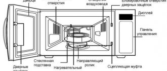
Continuity test of an asynchronous motor
This type of electric motor is quite often used in household devices operating from a 220 V network. After dismantling the unit from the device and visual inspection, during which no short circuit is detected, diagnostics are carried out in the following sequence:
- Measure the resistance between the motor terminals. This operation can be carried out with a multimeter, which must be switched to resistance measurement mode up to 100 Ohms. A working asynchronous motor should have a resistance of about 30 - 50 Ohms between one extreme and middle terminal of the connected winding, and 15 - 20 Ohms between the other extreme and middle contacts. These measurements indicate complete serviceability of the starting and main windings of the unit.
- Diagnose current leakage to ground. To test the unit for electric current leaks, you need to switch the multimeter operating mode to the resistance measurement position of up to 2,000 kOhm and alternately connect each terminal to the motor housing to determine the presence or absence of insulation damage. In all cases, the multimeter display should not show any readings. If an analog device is used to measure leakage, the needle should not deviate during diagnostic procedures.
How to find turn-to-turn short circuit
If you notice that a running engine heats up unevenly, that is, one part of the housing is hotter, then this may also indicate an interturn short circuit. But this is not a 100% way.
To search for an interturn short circuit, use a megohmmeter or multimeter and turn the switch to 200 ohms. We put it on each of the windings one by one and check the resistance. If the difference is more than 10-15%, it is better to rewind it.
Current follows the path of least resistance. When some of the turns are excluded from operation, then the resistance on that coil/winding will be lower.
Next, you can disassemble and visually evaluate the coils. It is even possible to identify burnt, melted wires this way. You will have to rewind the loose coil motor.
You can also measure the current on a running electric motor. First, check the voltage and then measure the current. At equal voltage, the current value should not differ by more than 15%.
Tips for choosing an electric motor
The main thing when choosing an electric motor is to select it in accordance with the conditions where it will be used. For example, splash-proof devices should be chosen for a humid environment, and open-type devices should absolutely not be exposed to liquids. Remember the following:
- Splash-proof motors can be used in damp and damp places. Their design is such that liquid cannot enter the device under the pressure of gravity or water flow;
- an open engine means that all its parts will be in plain sight. The devices have huge holes at the ends and the stator windings are clearly visible. These openings must absolutely not be blocked. and electric motors of this type cannot be used in wet, dirty or dusty areas;
- TEFC type motors can be used everywhere, except for those conditions for which they are not designed, which can be read in the user manual for the device.
So, we have listed the most common problems that can occur with household electric motors. Almost all of them can be recognized and certain measures can be taken by checking the device
We discussed above how to check it correctly and what details you should pay attention to first of all.
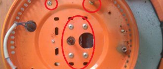
How to check electric motor bearings?
After inspecting the device, you can begin to check it, and this should be done starting with the engine bearings.
Very often, electric motor malfunctions occur due to their breakdown. They are needed to ensure that the rotor moves smoothly and freely in the stator. Bearings are located at both ends of the rotor in special niches. The most commonly used types of bearings for electric motors are:
Some need to be equipped with lube fittings. and some are already lubricated during the production process.
Bearings should be checked as follows:
- Place the engine on a hard surface and place one hand on its top;
- turn the rotor with your second hand;
- try to hear scratching sounds, friction and uneven movement - all this indicates a malfunction of the device. A working rotor moves calmly and evenly;
- we check the longitudinal play of the rotor; to do this, it needs to be pushed by the axis from the stator. A maximum play of 3 mm is allowed, but no more.
If there are problems with the bearings, the electric motor runs noisily, they themselves overheat, which can lead to failure of the device.
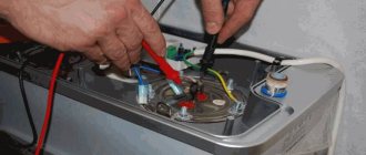
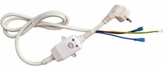
How to call: conditions
Before checking the electric motor for malfunction, you must make sure that the cord and plug of the device are absolutely in good working order. Usually, the absence of a disruption in the supply of electric current to the device can be judged by a glowing indicator lamp.
After making sure that electric current is supplied to the electric motor, it is necessary to dismantle it from the device body, while the device itself must be completely de-energized while performing this operation.
Checking the armature and stator of the electric motor is done with a multimeter. The sequence of measurements depends on the model of the electrical unit, and before ringing the electric motor, you should make sure that the measuring device is in working order.
The most common “breakdown” of multimeters is a decrease in battery charge, in which case you can get distorted results of resistance measurements.
Another important condition in order to ring an electrical unit correctly is to completely suspend any other activities and devote full time to performing diagnostic work, otherwise you can easily miss any section of the electric motor winding, which may be the cause of the problem.
Open field winding
Breakage of the excitation winding most often occurs in places where the ends of the winding are soldered to the slip rings.
When the field winding breaks, an EMF of no more than 5 V is induced in the stator winding, due to the residual magnetism of the rotor steel. If this malfunction occurs, the battery will not charge. To determine the break, it is necessary to disconnect the end of the field winding from the brush, and then connect the wires from the battery to this end and to terminal Ш of the generator through a lamp or voltmeter.
If the winding is broken, the lamp will not light up and the voltmeter needle will not deviate. To find a coil with a broken winding, wires from the battery terminals are connected to the ends of each coil. After this, carefully check the soldering joints and the output ends of the field winding coils. The discovered break point is eliminated by acid soldering using soft solders. When a break occurs inside the coil, it is replaced or rewound.