Sections of the article:
What wire cross-section is needed for 2-3-5 and 7 kW power
In order for the wire to withstand the load, it is necessary to correctly calculate the cross-section of its cores. When connecting sockets and lighting fixtures, as well as a number of different electrical appliances, wires of different sections are required.
The passport for the electrical appliance indicates its power - 2, 3, 5 or 7 kW. Therefore, in order to connect the device, you need to calculate the cross-section of the conductor cores. What you need to know for this, and how to correctly perform all the necessary calculations, read in this article on the website.
What wire cross-section is needed for a 5 kW load?
The correct choice of cable or wire for electrical wiring in a private house or apartment is the basis for the safe operation of electrical internal networks. The choice is based on the cable cross-section, which can be independently calculated using the formula: S=π*(D/2)²=S=π*R², where π is the Archimedean number (3.14), D is the diameter, and R – radius of cable cores. To clarify the topic of this article, we will answer the question, what wire cross-section is needed for a 5 kW load?
So, let's start with the fact that there is a regulatory document according to which you can choose a wire or cable for a load of 5 kW. This document is “Rules for Electrical Installations” or abbreviated as “PUE”. So, these rules indicate that there are three parameters that form the basis for choosing a section:
- the material from which the wire is made;
- supply voltage;
- current load in amperes or power in kilowatts.
If you choose the wrong wire cross-section based on current load or power consumption, it will definitely heat up, its insulation will melt, and there will be a high probability of a short circuit, often accompanied by fires. Therefore, you should not save on electrical wiring.
True, you shouldn’t overplay your hand by choosing a cross-section much larger than necessary. This will primarily affect your wallet, because wires with a larger cross-section are more expensive. Although it is necessary to calculate the possible increase in load with the advent of new household appliances in the future. But this must be done competently.
Automatic generator commissioning systems (AVR)
Purchasing ready-made ATS systems that connect the generator to the electrical network, or making them yourself for most household generator models is an inappropriate waste of money, since turning on generators, even with a built-in electric starter, is carried out under human control. This is due to the need to manually control the throttle valve (air supply to the internal combustion engine) when starting a cold engine and its subsequent heating. Fully automatic power supply backup systems can only be achieved when working with powerful generators equipped with microprocessor control systems.
Source
Criterias of choice
The PUE has tables from which you can select the wire cross-section. There are several of them. The thing is that there are a large number of wires themselves that are used in the electrical wiring of an apartment or house. Each wire has its own characteristics and technical characteristics, for example, an insulated sheath of bare wires. It can be made of PVC, rubber, with a protective sheath of lead and so on. Plus, there are two installation methods, which also determines what cross-section of wire to choose. The gasket can be open or closed.
Therefore, in order not to look at all the tables and search for the required cable parameter, we have created a summary table that takes into account all the above technical conditions with the addition of the material from which the wire is made. Here is the table:
Pivot table.
Since our task in this article is to select the wire cross-section for a load of 5 kW, it becomes clear from the table that:
- firstly, there is no such load, which means you will have to choose the nearest larger one, which is 5.5 kW;
- secondly, the voltage is selected: 220 or 380 volts;
- thirdly, the method of laying: by air or in the ground;
- Fourth, the raw material of the wire: copper or aluminum.
Since 5.5 kW for a small private house or a standard apartment is a normal load, it is better to connect a copper wire to them. And since most often this is laying through the air, it becomes clear from the table that for such an electrical supply you will need a wire with a cross-section of 2.5 mm². At the same time, it will withstand a current load of 25A.
But there is one point that concerns the nominal value of the input machine. It should be noted that this indicator is established by the project and approved by the energy supply organization. So the rating of the input circuit breaker with a load of 5.5 kW, that is, 25 amperes, should correspond to them. That is, at the entrance to the room, a 25 A circuit breaker is installed in the distribution board.
The rules stipulate that the wire supplied to the house or apartment must have a current rating higher than that of the machine. We look at the table, in which the next higher current load indicator is 35 amperes. We will take it as the actual value. Hence the other characteristics of the electrical wire:
- cross section – 4 mm²;
- withstand power – 7.7 kW.
For such installation conditions, you will need a VVGng wire, which will be laid in an open way.
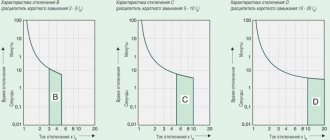
There is one more indicator that should be taken into account when selecting the wire cross-section. This is the so-called conditional breaking current. It will also depend on the circuit breaker installed in the distribution panel. This device has one characteristic, its name is time-current characteristic. So, for a machine with a rating of 25 amperes, the conditional shutdown current will be:
In a cold state, the circuit breaker at a given load will turn off only after an hour. As the temperature rises, this parameter decreases. Since the example we are considering has a wire cross-section of 4 mm², it corresponds to a long-term permissible current of 35 amperes. Let's compare it with the same indicator of the machine. The difference is insignificant, so you can leave everything as is. But under these conditions, experts recommend installing a wire with a cross-section of 6 mm², which corresponds to a long-term permissible current of 42 amperes.
Attention! The current load on the wires that power household appliances operating from a 220-volt network is greater than those operating from a 380-volt network.
You can calculate the current load manually, without resorting to tables. For example, if a cable is being calculated for connecting an electric stove or water heater with heating elements with a power of 3 kW. To do this, you will have to use Ohm’s law, or rather, its formula:
I=P/U, where P is power equal to 3 kW, U is voltage (380 V).
We substitute our values into the formula and get: I = 3000_380 = 7.89 A. Round up to 8 amperes. Now you can select a wire from the same table. In some cases, when calculating the current load, correction factors are used, but in domestic operating conditions of electric stoves and other equipment, where there are no high starting loads, they have a negligible value, so they are not used in these calculations. It is recommended to simply increase the current indicator by a small amount: 3-5 amperes, which is added to the calculated value.
From the calculations it becomes clear that for a 3 kW electric stove, a copper cable with a cross section of 2.5 mm² is suitable. And since a separate supply line is allocated for this device with a separately installed circuit breaker in the distribution board of an apartment or house, then, as under the conditions described above, it is necessary to take into account the time-current load. Therefore, the best option is a wire with a cross section of 4 mm². Exactly the same calculation can be made with any device of different power, or a calculation for the entire house, regardless of the technical connection conditions (it will be 10 kW or 15).
Minimum required to connect a generator
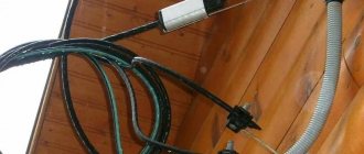
However, not much is needed to technically correctly connect the generator to the home electrical network. First of all, provide a separate input. It is recommended to use a high-section copper cable (at least 4 mm2) and lay it from the input distribution device to a specially equipped generator installation site.
You will also need a changeover switch. For domestic needs, many options for such devices have recently appeared in a modular design for mounting on a 35 mm DIN rail. Off the top of my head, you can offer a whole range of devices. From the cheapest products of the TDM-63 brand to more high-quality and reliable devices of the E200 series from ABB or SFB from Hager.
The devices have the simplest connection circuit and operating principle. As a rule, the common bus of outgoing loads is connected to the lower contacts. On the reverse side, where the contacts are paired, two separate inputs are connected. The switch key has three positions; on average, all circuits are open. In almost all series, the devices can be multi-pole, which will greatly facilitate work with a three-phase network and a complex grounding/zeroing system.
It is important to remember that a three-position (changeover) switch operates on the principle of a load switch; it does not have either a thermal or electromagnetic release. Therefore, each input must be additionally protected by an automatic circuit breaker, the current limit of which is determined by the permissible load on the supply line.
The simplest changeover device can be made by yourself from a pair of two-pole circuit breakers from the same manufacturer. They need to be placed side by side, one turned upside down, and then the keys connected together by inserting a steel pin into the standard hole.
Determination and calculation of maximum load
In order to connect the generator to the network, it is necessary to calculate the permissible load.
It is important to take into account not only the rated power, but also the inrush current, as well as a possible increase in energy consumption during operation of the device.
Therefore, the actual load may be greater than the rated power indicated on the appliance.
Simplified, the required power can be calculated by multiplying the rated power of the electrical appliance by the coefficient below:
- For incandescent lamps and heaters, a coefficient of unity can be taken;
- For household appliances (TV, refrigerator, fluorescent lamps) the coefficient will range from 1.2 to 1.5;
- Hand-held power tools (drill, angle grinder, jigsaw, milling cutter) - the coefficient will range from 1.5 to 2;
- Powerful equipment (pumps, welding transformers, machine tools, powerful electric motors without a soft start system) - 3.
Electrical connection
It is important to remember the main rule: “More than one source of electricity cannot be connected to the electrical network at the same time.” Failure to comply with this rule guarantees breakdown.
Connecting a generator as the only source of electricity
In nature or in a country house, where there are no other sources of electricity other than a generator, the connection is made through sockets built into the housing. The maximum current of single-phase sockets is in the range of 16–20 A, three-phase - 40–50 A. It is necessary to use both special and regular extension cords, depending on the type of output socket.
Generator VAZ 2110
The VAZ 2110 generator is a synchronous AC electric machine with electromagnetic excitation and a built-in rectifier using silicon diodes. The generator rotor is driven into rotation from the engine crankshaft pulley (damper) by a poly-V belt.
Technical characteristics of generator 94.3701 VAZ 2110
The excitation winding is located on the rotor of the VAZ 2110 generator, its leads are soldered to two copper slip rings on the rotor shaft. Power is supplied to the field winding through two carbon brushes. The brush holder is structurally combined with the voltage regulator and is mounted on the back cover of the generator.
The VAZ 2110 voltage regulator is non-separable; if it fails, it is replaced.
To protect the on-board network from voltage surges during operation of the ignition system and reduce interference with radio reception, a capacitor with a capacity of 2.2 μF (±20%) is connected between the terminals of the “positive” and “negative” valves (between the “+” and “ground” of the generator) on the rectifier block.
Connection diagram for generator VAZ 2110 94.3701
Electrical diagram of the VAZ 2110 generator: 1 - battery, 2 - generator, 3 - relay and fuse block (mounting block), 4 - ignition switch, 5 - instrument cluster, 6 - battery discharge warning lamp (installed from 1997 to 1997 year, an electronic voltmeter with an LED was installed).
Diagnostics of the VAZ 2110 generator
Replacing the VAZ 2110 alternator belt
Using a 13mm wrench, loosen the nut securing the generator to the mounting bar
Using a 10mm wrench, turn the adjusting bolt counterclockwise to loosen the tension on the generator drive belt.
Having moved the generator towards the cylinder block, remove the belt. We install the VAZ 2110 generator belt in the reverse order and tighten it by rotating the adjusting bolt
When applying a force of 98 N (10 kgf), the normal belt deflection should be within 6–10 mm.
Removal and installation of the VAZ 2110 generator
Disconnect the negative wire from the battery and the generator excitation wire
Using a 10mm wrench, unscrew the nut securing the wires to terminal “B+” and remove them. Remove the generator belt, unscrew the generator adjusting bolt and unscrew the fixing nut
Using a 13mm wrench, unscrew the nut of the lower mounting of the generator
Remove the bolt and remove the generator. Installation of the generator on the VAZ 2110 is carried out in the reverse order of removal.
Proper nutrition from LOUD SOUND
1.
The main thing is nutrition. The audio system should start with it.
2.
The best power supply should be from the most
powerful amplifier
- usually a subwoofer amplifier
3. How to choose wire thickness?
It’s very simple - read 100,500 articles about choosing the thickness of the wire, complete the “car audio school” courses, make complex calculations on a slide rule, and be sure to complete the “Theoretical Fundamentals of Electrical Engineering” course at some university.
Or choose this:
- up to 800 Watt – 4Ga (25kW),
- 800+ W – 2 Ga (35 kW),
- 1.5 kW and more – 0ga (50 kW)
We are talking about the total power of the system
. If you choose a wire that is too thick, it’s okay, if it’s too thin, there will be a loss of voltage from the beginning of the wire to the end. That is, under the hood there will be 12.5 Volts, on the monoblock 11.5 Volts - this is very, very high. not good, since in this case you not only risk burning the amplifiers, but also warm up the wire. And the thinner it is, the more it will warm up.
For clarity, if you power the amplifier with a thin wire, it will become red-hot. If at the same time it is in a silicone braid. Well, you understand.
4
.
A voltmeter
is
a must
. In any form, but you must know what is happening in the system on which tracks. At a minimum, you should measure the voltage after starting the audio system in two places:
- under the hood
- and on the largest consumer (usually a monoblock) -
The voltage should be the same and not drop below 12 Volts.
5.
Forget about capacitors (storage devices)
. The only benefit from a capacitor is a voltmeter, if it has one, but if not, the capacitor is only useful to the capacitor seller. The capacitor is not cheap - it’s better to buy a thicker wire or an additional battery
6
.
How to choose an additional battery?
Ideally, it should be exactly the same as under the hood, even better if they are
both new.
If it is not possible to install the same one, let them be of the same type:
- both AGM,
- or both lithium.
You can put an AGM together with acid, or even an AGM together with lithium - but a battery with a high voltage will be constantly in a state of discharge until the overall voltage levels out. In practice, I used AGM and acid many times and nothing happened in a year or more of use.
7.
How to connect
an additional battery? Relays, adapters - on. all this - just connect plus with plus and minus with minus.
8.
In addition to strong consumers,
do not forget about the weakest one - the GU
(radio tape recorder) - do not power it from the cigarette lighter or from random wiring on which you will find plus and minus.
Don’t be lazy - drag both the plus and minus from the same place where you got the power for the amplifiers. This way there will be a lower risk of interference and the radio will not turn off when you start the car.
Maintenance contract
To carry out maintenance, you must conclude a service agreement with a certified service center. In this case, you can use the services of a service and installation service that installed and commissioned the generating set.
The service life of the power plant you purchased and the safety of its operation directly depend on how competently the installation was carried out
Mistakes made when attempting to install a generator yourself can result in expensive equipment failure or safety violations.
Also, important points that ensure proper operation of the generator may not be taken into account: accounting and control of noise levels, ease of maintenance and repair, and much more. Top
Selecting the cable cross-section according to power
You can select the wire cross-section according to the power of the devices that will be connected. These devices are called load and the method can also be called “by load”. Its essence does not change from this.
The choice of cable cross-section depends on the power and current
Collecting data
First, find the power consumption in the passport data of household appliances and write it down on a piece of paper. If it’s easier, you can look at nameplates - metal plates or stickers attached to the body of equipment and equipment. There is basic information and, more often than not, power. The easiest way to identify it is by its units of measurement. If a product is manufactured in Russia, Belarus, or Ukraine, it is usually designated W or kW; on equipment from Europe, Asia or America, the English designation for watts is usually W, and the power consumption (this is what is needed) is designated by the abbreviation “TOT” or TOT MAX.
Example of a nameplate with basic technical information. There is something similar on any technology
If this source is also unavailable (the information has become lost, for example, or you are just planning to purchase equipment, but have not yet decided on the model), you can take the average statistical data. For convenience, they are summarized in a table.
Table of power consumption of various electrical appliances
Find the equipment you plan to install and write down the power. Sometimes it is given with a wide spread, so sometimes it is difficult to understand which figure to take. In this case, it is better to take the maximum. As a result, when calculating, you will slightly overestimate the power of the equipment and will need a cable with a larger cross-section. But for calculating the cable cross-section it is good. Only cables with a smaller cross-section than necessary will burn. Routes with a large cross-section work for a long time, as they heat up less.
The essence of the method
To select the wire cross-section for the load, add up the power of the devices that will be connected to this conductor. It is important that all powers are expressed in the same units of measurement - either in watts (W) or in kilowatts (kW). If there are different values, we bring them to a single result. To convert, kilowatts are multiplied by 1000 to get watts. For example, let's convert 1.5 kW into watts. This will be 1.5 kW * 1000 = 1500 W.
If necessary, you can carry out the reverse conversion - convert watts to kilowatts. To do this, divide the figure in watts by 1000 to get kW. For example, 500 W / 1000 = 0.5 kW.
Next, the selection of the cable cross-section actually begins. It's very simple - we use a table.
| Cable cross-section, mm2 | Conductor diameter, mm | Copper wire | Aluminum wire | ||||
| Current, A | power, kWt | Current, A | power, kWt | ||||
| 220 V | 380 V | 220 V | 380 V | ||||
| 0.5 mm2 | 0.80 mm | 6 A | 1.3 kW | 2.3 kW | |||
| 0.75 mm2 | 0.98 mm | 10 A | 2.2 kW | 3.8 kW | |||
| 1.0 mm2 | 1.13 mm | 14 A | 3.1 kW | 5.3 kW | |||
| 1.5 mm2 | 1.38 mm | 15 A | 3.3 kW | 5.7 kW | 10 A | 2.2 kW | 3.8 kW |
| 2.0 mm2 | 1.60 mm | 19 A | 4.2 kW | 7.2 kW | 14 A | 3.1 kW | 5.3 kW |
| 2.5 mm2 | 1.78 mm | 21 A | 4.6 kW | 8.0 kW | 16 A | 3.5 kW | 6.1 kW |
| 4.0 mm2 | 2.26 mm | 27 A | 5.9 kW | 10.3 kW | 21 A | 4.6 kW | 8.0 kW |
| 6.0 mm2 | 2.76 mm | 34 A | 7.5 kW | 12.9 kW | 26 A | 5.7 kW | 9.9 kW |
| 10.0 mm2 | 3.57 mm | 50 A | 11.0 kW | 19.0 kW | 38 A | 8.4 kW | 14.4 kW |
| 16.0 mm2 | 4.51 mm | 80 A | 17.6 kW | 30.4 kW | 55 A | 12.1 kW | 20.9 kW |
| 25.0 mm2 | 5.64 mm | 100 A | 22.0 kW | 38.0 kW | 65 A | 14.3 kW | 24.7 kW |
To find the required cable cross-section in the corresponding column - 220 V or 380 V - we find a figure that is equal to or slightly greater than the power we previously calculated. We select the column based on how many phases are in your network. Single-phase - 220 V, three-phase 380 V.
In the found line, look at the value in the first column. This will be the required cable cross-section for a given load (power consumption of devices). You will need to look for a cable with cores of this cross-section.
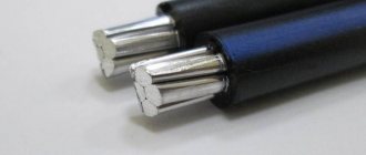
A little about whether to use copper wire or aluminum. In most cases, when laying wiring in a house or apartment, cables with copper conductors are used. Such cables are more expensive than aluminum ones, but they are more flexible, have a smaller cross-section, and are easier to work with. But copper cables with a large cross-section are no more flexible than aluminum ones. And under heavy loads - at the entrance to a house or apartment with a large planned power (from 10 kW or more), it is more advisable to use a cable with aluminum conductors - you can save a little.
Possible problems and malfunctions
When using a generator, you must have a complete understanding of the nature of the current generated by the autonomous source. Often these are not the usual phase and zero, but alternating phases with a half-wave of 110–125 V relative to ground.
Such generators require a high-quality grounding system that is not connected to the protective conductor of the home network. Also, both the phase and neutral wires of both inputs must be switched, otherwise leakage into the city network is guaranteed.
This is the main reason that when connected through an outlet, the circuit breaker on the generator itself is triggered. As for differential protection devices, they will have to be installed in pairs - one for each input. An exception to this rule is three-phase networks, but they, in turn, require the installation of separate grounding and grounding circuits for stable and uninterrupted operation.
Source
Cable calculation by power and length
If the power transmission line is long - several tens or even hundreds of meters - in addition to the load or current consumed, it is necessary to take into account losses in the cable itself. Long distances of power lines are common when introducing electricity from a pole into a home. Although all data must be indicated in the project, you can play it safe and check. To do this, you need to know the allocated power per house and the distance from the pole to the house. Next, using the table, you can select the wire cross-section taking into account losses along the length.
Table for determining cable cross-section by power and length
In general, when laying electrical wiring, it is always better to take some margin in the cross-section of the wires. Firstly, with a larger cross-section, the conductor will heat up less, and therefore the insulation. Secondly, more and more devices powered by electricity are appearing in our lives. And no one can guarantee that in a few years you won’t need to install a couple more new devices in addition to the old ones. If stock exists, they can simply be included. If it’s not there, you’ll have to get smart—either change the wiring (again) or make sure that powerful electrical appliances don’t turn on at the same time.
Common generator failures on Japanese cars
Car alternators often need to be replaced due to wear and tear of parts. The most common breakdowns that occur are:
- wear of the current collection brushes, which interferes with battery charging. During this failure, the warning light usually goes out and comes on periodically. The brushes can be replaced, but you need to take into account that powerful Japanese generators use exclusively carbon-graphite brushes; carbon brushes are not suitable;
- jamming of brushes in the slots of slip rings;
- oxidation and melting of the end of a thick wire with a terminal, screwed to the generator with a nut, also leads to the disappearance of charging. After stripping or replacing the wire, you must tighten the nut well to prevent such situations in the future;
- breakage of thin wires connecting the generator to the battery;
- short circuit in the winding (visually determined by traces of burning on the varnish covering the wires);
- burnout of diodes, burnout of their terminals;
- in models with a vacuum pump - breakage of the blades, cutting off the splines on the generator shaft or in the pump.
Useful tips Connection diagrams Principles of operation of devices Main concepts Meters from Energomer Precautions Incandescent lamps Video instructions for the master Testing with a multimeter
Open and closed wiring
As we all know, when current passes through a conductor, it heats up. The higher the current, the more heat generated. But, when the same current passes through conductors with different cross-sections, the amount of heat generated changes: the smaller the cross-section, the more heat is released.
In this regard, when the conductors are laid open, its cross-section may be smaller - it cools down faster, since heat is transferred to the air. In this case, the conductor cools down faster and the insulation does not deteriorate. When the gasket is closed, the situation is worse - heat is removed more slowly. Therefore, for closed installations - in cable ducts, pipes, in the wall - it is recommended to take a cable with a larger cross-section.
The choice of cable cross-section, taking into account the type of installation, can also be made using the table. The principle was described before, nothing changes. There's just one more factor to consider.
Selection of cable cross-section depending on power and type of installation
And finally, some practical advice. When going to the market to buy a cable, take a caliper with you. Too often the stated cross-section does not coincide with reality. The difference can be 30-40%, which is a lot. What does this mean for you? Burnout of wiring with all the ensuing consequences. Therefore, it is better to check right on the spot whether a given cable actually has the required core cross-section (the diameters and corresponding cable cross-sections are in the table above). more about determining the cable cross-section by its diameter here .
Turnkey generator installation
- Turnkey installation of the generator is carried out according to the estimate approved by the customer and agreements reached.
- The work from the item “Preparation of the facility for installation of a power plant” is being carried out.
- The laying of electrical and diesel lines is organized if the diesel generator has an additional tank installed.
- If the installation is carried out indoors, then it will be equipped with supply and exhaust ventilation, an exhaust gas removal and fire extinguishing system, heating in winter if the room is not heated, etc.
Further according to the paragraph “Installation Supervisor”.
Top