What cables can be laid underground?
In the trench, the cable is protected from temperature changes, solar radiation, rain moisture, strong wind, and icing. But there are some striking factors here:
- ground movements;
- rodents;
- the likelihood of damage during excavation work.
It follows that the conductor must have increased mechanical strength.
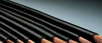
Therefore, for laying in the ground they use:
- armored cables that have metal tape or wire in their design;
- simple AVVG and VVG in a pipe or corrugation.
The first option is considered preferable.
SNiP 3.05.06-86 and GOST 16442-80 allow the laying of simple VVG or AVVG without protection if:
- soil corrosivity is low or moderate;
- no tensile load;
- the section is laid horizontally;
- the soil is not swampy, unfilled and not heaving.
SIP wire cannot be used for underground installation, even in a pipe.
Its insulation quickly deteriorates due to frequent condensation.
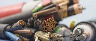
Cable Specifications
Explorer properties describe the following parameters:
- core material – aluminum or copper;
- their number and section;
- their type - monolithic or stranded;
- material and flammability class of insulation and shell;
- Rated voltage;
- maximum permissible long-term heating temperature;
- the same in short-term mode (during a short circuit);
- minimum bend radius;
- tensile strength;
- cost per linear meter;
- design: presence of armor, waterproofing, number of layers in the shell, etc.
Labeling with explanation
The main characteristics of the cable are usually designated by an alphanumeric code. For example, the following can be said about the product brand AVVGng-ls 3x16:
- A – aluminum cores. If this letter is not present at the beginning, it means the cable is copper (VVG).
- VV - core insulation and sheath are made of vinyl or PVC. Other options are polyethylene (P), self-extinguishing polyethylene (Ps) and paper impregnated with oil rosin (C in front of the designation).
- G – “naked”. This means that there is no special protection.
- ng – non-combustible insulation. The material is assumed to be non-flammable.
- hp – low smoke emission (from the English low smoke).
- 3x16 – 3 cores with a cross section of 16 sq. mm.
The presence of armor is indicated by the letters:
- B – from tape;
- K – from round steel wire (Ka – aluminum);
- P - from flat.
Shell type:
- Shv – vinyl hose;
- Shp - the same from polyethylene.
A small “b” means the presence of a bitumen layer, “l” means a layer of plastic tapes under the armor.
For example, VBBShV cable is often used for underground installation. It has copper conductors (the letter “A” is missing), PVC insulation (B), tape armor (B) and a bitumen layer (b), and a vinyl hose (Shv) on the outside.
The combination “AA” denotes aluminum conductors in the same sheath, “AC” – lead conductors.
Products made from low-density polyethylene
The most obvious popularity is the HDPE pipe for laying cables in the ground; it is divided into two main types:
- technical – general purpose;
- electrical – designed specifically for the installation of underground cable ducts.
Technical
Power transmission lines and other utility networks can be laid in different pipes. Technical pipes that have smooth single-layer walls and are painted black are also quite suitable for these purposes. They have all the necessary characteristics: resistance to aggressive chemicals, mechanical strength, electrical insulating properties.
Technical single-layer pipes Source yahplastic.com.pk
Since such products have a universal purpose, they are not equipped with devices for tightening the cable.
Smooth single-wall polyethylene pipes are rigid and flexible. Laying HDPE pipes in the ground is permitted only in a rigid version, as is pouring the cable into a concrete floor screed or laying it in brickwork. Flexible tubes are used to protect electrical wiring inside the house.
See also: Catalog of companies that specialize in electrical work of any complexity
Electrical
Double-wall pipes are more suitable for underground networks. They can accommodate power lines with AC or DC voltages up to 1000 V.
Double-wall pipes are produced smooth and corrugated, their outer shell is made of HDPE, and the smooth inner shell is made of another type of PE - high-density polyethylene. The most durable and reliable products are those with corrugated outer walls, which are reinforced with thin steel wire.
Double-wall corrugated pipes Source twimg.com
Laying a cable in the ground in a HDPE pipe of this type is characterized by maximum simplicity and speed of installation due to smooth internal walls that do not create obstacles for its pulling. And the outer corrugated shell has excellent ring rigidity and does not wrinkle or break under the weight of a thick layer of soil. At the same time, corrugated pipes have a low dead weight, which also facilitates transportation, placement in trenches and assembly.
The features of the material, which retains strength and elasticity at any temperature, resistance to chemically aggressive environments and ultraviolet sunlight, do not create problems during storage and allow installation both in the summer heat and in the winter cold.
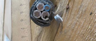
Features of armored cables for underground installation
This cable includes the following elements:
- Conducting conductors. Conducts electricity from source to consumer.
- Their isolation. Eliminates contact of cores with each other, which would lead to a short circuit.
- Cable filler. Serves as a sealed package for the conductors, gives the conductor its shape and makes it durable.
- Waist insulation. Combines current-carrying conductors into a monolithic structure. Also serves as additional insulation.
- Protective shell. Protects the cores from the effects of environmental factors, gives the cable strength and rigidity.
- Pillow shell. Protects the previous element from damage by the subsequent layer.
- Steel armor. Protects the product from damage.
- Outer cover. Protects the previous layer from environmental chemical aggression.
Calculation of cable cross-section by length: formula
The cable length affects the voltage loss. Thus, the voltage at the end of the conductor may decrease and be insufficient to operate the electrical appliance. For household electrical networks, these losses can be neglected. It will be enough to take a cable 10-15 cm longer. This reserve will be used for switching and connection. If the ends of the wire are connected to the shield, then the spare length should be even greater, since circuit breakers will be connected.
1️⃣ First step. First, the rated current in the circuit is determined:
I = Psum / (U × cos ϕ)
- Psum – total power of electrical appliances;
- U – network voltage;
- cos ϕ – power factor (characterizes power losses), default is 0.92.
2️⃣ Second step. Then the conductor resistance is calculated:
R = dU/I
- dU – voltage loss, no more than 5% (0.05);
- I – current strength.
3️⃣ Third step. The cross-section of the current-carrying conductor is calculated using the formula:
S = ρ × L/R
- ρ – metal resistivity, copper (0.0175), aluminum (0.028);
- L – conductor length;
- R – conductor resistance.
Requirements for underground cable laying
The rules for installing a power line in a trench are set out in clause 2.3.83 of the PUE and subsequent ones, as well as in SNiP 3.05.06-86. For cables with voltages up to 20 kV, which include household cables at 220V, 380V and industrial cables at 10 kV, the minimum depth is:
- under an area not subject to loads (lawns, etc.) – 0.7 m;
- under the road, paved area, sidewalk - 1 m.
For entry into the house, it is allowed to reduce this parameter to 0.5 m, but only on a plot of no more than 5 (m) in length.
If several cables need to be laid in a trench, the minimum distance between them is 10 cm.
The shortest distance between the route and various objects on the site (m):
- foundation – 0.6;
- power or communication line of a third party – 0.5;
- tree – 2;
- bush – 0.75;
- pipeline, sewerage – 1;
- heat pipeline, for example DHW – 2;
- gas pipeline with pressure up to 0.588 MPa - 1, above 0.588 MPa - 2.
When laid along a building, the cable should be behind an imaginary line drawn from the edge of the foundation base downward at an angle of 45°.
It is prohibited to lay conductor above and below cable routes and pipelines. They can only be crossed, and both lines must be separated by a layer of earth at least 0.5 m thick.
How to calculate cable cross-section by power: formula
Before choosing a cable cross-section based on power, you need to calculate its total value and make a list of electrical appliances located in the territory to which the cable is laid. The power must be indicated on each device; the corresponding units of measurement will be written next to it: W or kW (1 kW = 1000 W). Then you will need to add up the power of all equipment and get the total.
1️⃣ First step. The total power of all electrical appliances that can be connected to the network is calculated:
Psum = (P1 + P2 + .. + Pn) × Kс
- P1, P2 .. – power of electrical appliances, W;
- Kc – demand coefficient (probability of simultaneous operation of all devices), default is 1.
2️⃣ Second step. Then the rated current in the circuit is determined:
I = Psum / (U × cos ϕ)
- Psum – total power of electrical appliances;
- U – network voltage;
- cos ϕ – power factor (characterizes power losses), default is 0.92.
3️⃣ Third step. At the last stage, tables are used in accordance with the PUE (Electrical Installation Rules).
Table of copper cable cross-section by current according to PUE-7
| Conductor cross-section, mm2 | Current, A, for wires laid | |||||
| open | in one pipe | |||||
| two single-core | three single-core | four single-core | one two-wire | one three-wire | ||
| 0.5 | 11 | – | – | – | – | – |
| 0.75 | 15 | – | – | – | – | – |
| 1 | 17 | 16 | 15 | 14 | 15 | 14 |
| 1.2 | 20 | 18 | 16 | 15 | 16 | 14.5 |
| 1.5 | 23 | 19 | 17 | 16 | 18 | 15 |
| 2 | 26 | 24 | 22 | 20 | 23 | 19 |
| 2.5 | 30 | 27 | 25 | 25 | 25 | 21 |
| 3 | 34 | 32 | 28 | 26 | 28 | 24 |
| 4 | 41 | 38 | 35 | 30 | 32 | 27 |
| 5 | 46 | 42 | 39 | 34 | 37 | 31 |
| 6 | 50 | 46 | 42 | 40 | 40 | 34 |
| 8 | 62 | 54 | 51 | 46 | 48 | 43 |
| 10 | 80 | 70 | 60 | 50 | 55 | 50 |
| 16 | 100 | 85 | 80 | 75 | 80 | 70 |
| 25 | 140 | 115 | 100 | 90 | 100 | 85 |
| 35 | 170 | 135 | 125 | 115 | 125 | 100 |
| 50 | 215 | 185 | 170 | 150 | 160 | 135 |
| 70 | 270 | 225 | 210 | 185 | 195 | 175 |
| 95 | 330 | 275 | 255 | 225 | 245 | 215 |
| 120 | 385 | 315 | 290 | 260 | 295 | 250 |
| 150 | 440 | 360 | 330 | – | – | – |
| 185 | 510 | – | – | – | – | – |
| 240 | 605 | – | – | – | – | – |
| 300 | 695 | – | – | – | – | – |
| 400 | 830 | – | – | – | – | – |
Table of cross-section of aluminum cable by current according to PUE-7
| Conductor cross-section, mm2 | Current, A, for wires laid | |||||
| open | in one pipe | |||||
| two single-core | three single-core | four single-core | one two-wire | one three-wire | ||
| 2 | 21 | 19 | 18 | 15 | 17 | 14 |
| 2.5 | 24 | 20 | 19 | 19 | 19 | 16 |
| 3 | 27 | 24 | 22 | 21 | 22 | 18 |
| 4 | 32 | 28 | 28 | 23 | 25 | 21 |
| 5 | 36 | 32 | 30 | 27 | 28 | 24 |
| 6 | 39 | 36 | 32 | 30 | 31 | 26 |
| 8 | 46 | 43 | 40 | 37 | 38 | 32 |
| 10 | 60 | 50 | 47 | 39 | 42 | 38 |
| 16 | 75 | 60 | 60 | 55 | 60 | 55 |
| 25 | 105 | 85 | 80 | 70 | 75 | 65 |
| 35 | 130 | 100 | 95 | 85 | 95 | 75 |
| 50 | 165 | 140 | 130 | 120 | 125 | 105 |
| 70 | 210 | 175 | 165 | 140 | 150 | 135 |
| 95 | 255 | 215 | 200 | 175 | 190 | 165 |
| 120 | 295 | 245 | 220 | 200 | 230 | 190 |
| 150 | 340 | 275 | 255 | – | – | – |
| 185 | 390 | – | – | – | – | – |
| 240 | 465 | – | – | – | – | – |
| 300 | 535 | – | – | – | – | – |
| 400 | 645 | – | – | – | – | – |
In the Electrical Installation Rules, 7th edition, there are no tables of cable cross-section by power, there is only data on current strength. Therefore, when calculating sections using load tables on the Internet, you risk getting incorrect results.
Instructions for laying cables underground
The initial stage involves the following actions:
- The administration of the locality receives a site plan with existing underground utilities.
- Based on the drawing, they develop their own scheme for laying the line, linking it to stationary objects.
- Using pegs and twine, markings are made on the site.
Digging a trench
The width of the trench is selected taking into account the following regulatory requirements:
- the distance between cables is 10 cm;
- the sand cushion extends 10 cm beyond the outer conductor.
The depth of the trench is 200 mm more than the normal line level, i.e.:
- on the lawn - 0.9 m;
- under the road – 1.2 m.
Having dug a trench to the required depth, proceed in this order:
- Clear the bottom of large rhizomes, stones, glass and other debris. All this can damage the cable.
- A layer of sand 20 cm thick is poured. It prevents damage to the shell and, due to its drainage properties, removes moisture.
- They compact the sand, moistening it abundantly with water (it is better to do this in layers) so that its thickness is 15 cm. Without this, the bedding will sag and voids will form under some sections of the cable, which will lead to its local overheating. Uneven temperature distribution will lead to deformation of the product with subsequent damage to the insulation.
- Lay the conductor on the sand along a wave-like path. This ensures the required length margin of 2%, which prevents rupture of the product due to ground movements.
- A control measurement of the insulation resistance between the cores and the shell is carried out. For this you need a megohmmeter.
- A layer of sand 20 cm thick is poured on top. It is also moistened and compacted so that the height of the pillow is 15 cm.
- Pour 15 cm of soil. They also ram it.
- Place orange plastic warning tape with the inscription “Caution, cable!” If there are several conductors in the trench, use 2 or 3 warning plastics so that they extend beyond the outer lines by 5 cm.
- They dig a trench. To compensate for future shrinkage, the soil is poured with a small margin.
- Check the insulation resistance again with a megohmmeter. The probes of the device are connected to the conductors in pairs, then in turn to each of them and to the shell.
Selecting cable cross-section based on current strength: calculation formula
The amount of current passing through a conductor depends on the length, width, resistivity of the latter and on temperature. When heated, the electric current decreases.
1️⃣ First step. The calculation is carried out in exactly the same way, that is, first the total power of all electrical appliances that can be connected to the network is calculated:
Psum = (P1 + P2 + .. + Pn) × Kс
- P1, P2 .. – power of electrical appliances, W;
- Kc – demand coefficient (probability of simultaneous operation of all devices), default is 1.
2️⃣ Second step. Then the rated current in the circuit is determined:
I = Psum / (U × cos ϕ)
- Psum – total power of electrical appliances;
- U – network voltage;
- cos ϕ – power factor (characterizes power losses), default is 0.92.
3️⃣ Third step. At the last stage, the same tables are used, according to the PUE (Electrical Installation Rules), which are located above.
Safety precautions
When installing the cable, observe the following rules:
- The cable drum is unloaded using lifting equipment.
- When rolling it, measures are taken to prevent the protruding parts from catching the fitters’ clothes.
- The drum is moved only on a horizontal surface; it is prohibited to stand in its path.
- When rolling, the reels do not approach the trench closer than 1 m.
- The cable is unwound using canvas gloves.
- The conductor is carried on the shoulder facing the direction of the trench; all workers should be on one side of him.
- The maximum permissible load per worker is 35 kg.
- If, when digging a trench, they come across communications that are not indicated on the plan, the work is suspended and they begin to search for the owner or operating organization.
In places where the route turns, it is prohibited to stand inside the corner, support the cable or pull it by hand. Special rollers are installed here.
Only a certified installer has the right to test cable insulation using a megohmmeter. This is due to the fact that during operation this device generates voltage up to 2500 V. After checking, you need to discharge the cable to the ground or short-circuit its wires.
What you need to know when installing
Outdoor lighting cable that will be placed in the ground must have an adequate level of protection against potential or accidental damage. These requirements are clearly stated in the regulatory documents described above. The developed project must indicate the type and features of the cable to be laid. If it is made of polyethylene, then for its proper installation in the trench, the wire must be in a special pipe.
Note! Placing it in a special pipe will reliably protect the wire from any external mechanical damage.
Pipes at the bottom of the trench
There are situations when an armored cable is used (for example, VBBShV). In this case, pipe installation does not occur. This is done only in those places where the cable will be laid under the roadway (according to the requirements of SNiP and GOST). For such an armored cable for the lawn part, the laying depth must be at least 0.8 m (smallest permissible value) from the fixing (reference) mark on the ground. When placed under the road, the depth will be no less than 1.25 m. The cable for street lighting is laid as follows:
- a layer of sand 15 cm thick is poured into the trench at the bottom;
- then the sand is abundantly moistened with water, which will simplify and make further compaction more effective;
- special vibrating plates should be used to compact sand;
Note! After compaction, the 15 cm layer of sand should turn into 10 cm.
Vibrating plates for compacting sand
- after this, electrical measurements of the cable should be carried out to ensure that there are no holes in the insulation;
- Direct installation begins from the cable entry into the structure or building. Laying the wire, if there are lighting poles, starts from the last pole;
- then the cable is unwound along the entire length of the prepared trench. In this case, it is necessary to give allowances for connecting the wires to the lighting poles (if they are installed);
Note! The size of the allowance will depend on the installation location in the junction box post.
- To install the wire in the support, you need to cut out a technical window in it. It can be prepared in advance. A cable is inserted into it. A similar procedure is repeated for all existing lighting poles.
Cable laid in a trench
After the cable has been laid along the entire length of the trench and brought to all the poles, it is necessary to perform electrical measurements again. They will help ensure that during the installation process the power cable was not damaged in any area of the insulation. These requirements are specified in the regulatory documentation.
How to lay a wire between living spaces
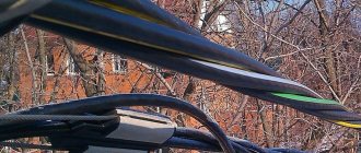
Laying wires between houses is possible in 2 ways - by air or underground. Part of the overhead line can run along the facade of the building.
Between buildings that are close to each other, you can find a line of simple wires. Often they are stretched from one house to another without grounding and compliance with regulations. Such installation can lead to breaks and fire.
Is grounding necessary?
Special clamps, which are used to secure the wire to the overhead line cable, have connectors for connecting portable measuring instruments. You can also connect a mobile protective ground there.
Grounding is performed before tensioning the wire.
The TN-CS system (transformer substation with solidly grounded neutral) consists of 2 or 4 SIP cables. They are used for overhead power line wiring. One conductor is considered the main conductor (PEN), the rest are phases. PEN is divided into two wires - protective zero (PE) and working zero (N).
Grounding is performed immediately before tensioning the wire on the support. For this purpose, steel wire is used. Its diameter should not be less than 6 mm. In concrete pillars, metal reinforcement is located inside the structure.
Housings of lamps, panels and other metal structures must be connected to the zero phase.
Preparation
After carrying out the necessary calculations, the cable cross-section is determined. The brand is chosen based on the method of laying the line. For overhead you will need SIP, and for underground - AVBbShv.
Before starting work, you need to uproot stumps and remove any foreign objects along the route, collect and prepare the necessary tools. Then you need to purchase the required amount of wire and elements for its fastening.
Posting by air
For wiring, old poles should be removed, if necessary, and new ones installed. Securely fix all fastening elements on them and ensure grounding.
The cable is raised to a height and tensioned using rollers.
The cable is sold in reels. Before installation, it needs to be rolled out, but not on the ground. For this purpose, special rolling carts are used. Otherwise, the insulating layer of the conductor may be damaged.
The cable is raised to a height. Then they are tensioned using rollers. After fixing the wire with anchor clamps, they are removed. A team of workers is required to complete this work. Special equipment may be required.
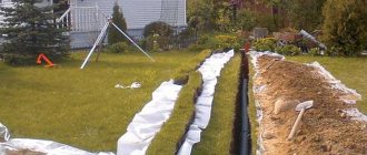
Deep installation
Special attention should be paid to the choice of cable. For swampy areas or soil with a high salt content, reinforced armored wire will be required.
At a distance of at least 60 cm from the building, a trench is dug up to 130 cm deep and at least 30 cm wide. Its bottom is leveled with a layer of sand, which must be filled to a depth of 10 cm. A cable is laid on top of it without tension. It should lie freely.
Another layer of sand is poured over the wire and fresh soil is laid, leaving 15–20 cm for the signal tape. Then the trench is buried to the end.
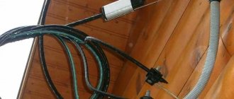
Along the walls of the building
From the living room the cable is routed to the wall. There it is attached with special clamps to the brackets. The wiring along the wall is fixed with clamps.
The procedure for attaching the cable:
- On the facade of the house, holes are drilled in the right places into which dowel-nails (plastic clips made from a cap and a screw) are inserted.
- Dowels are used to secure brackets to the wall and clamps.
- Install the wire.
Copper flexible wires of low rated voltage can be laid inside a metal pipe attached to the facade of the building.