How to calculate load resistance?
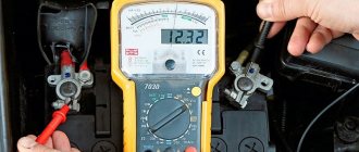
Direct measurement of DC resistance is carried out with ohmmeters. If resistance values are more than 1 Ohm, ohmmeters with a series measurement circuit are used, and for measuring low resistances - with a parallel circuit.
Interesting materials:
How did Ibrahim die in the magnificent century? How did the composer Tchaikovsky die? How did Mehmet die in the series The Magnificent Century? How did P A Stolypin die? How did the stationmaster die? How did Larisa from Sklifosovsky die? How does Andrei Bolkonsky die? How to multiply and divide powers with the same bases? How will Hatice die in the series The Magnificent Century? How to pack a violet for mailing?
How to connect a voltmeter and take measurements?
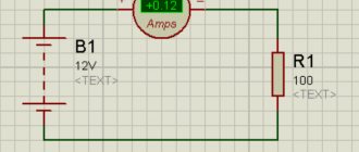
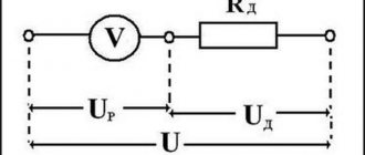
Voltmeters should always be connected in parallel with the electrical device or element on which the electrical voltage is measured (Figure 2).
Rice. 2. Method for measuring electrical voltage at the ends of element R
The key idea is that the voltmeter terminals are connected to those points in the electrical circuit between which the electrical voltage must be measured .
However, it should be remembered that with such a connection, part of the current IV will flow through the voltmeter, and not through the element being tested R. Thus, we are dealing with a situation where the action of measuring a physical quantity changes the value of this quantity. This is not the only similar example in physics.
As can be seen from the previous discussions, to measure the true value of the electrical voltage at the ends of a circuit element, we need a voltmeter with infinite resistance. Then no electric current will flow through the measuring device, so the measurements will be undistorted. In practice, it is impossible to realize infinite electrical resistance in a voltmeter. However, voltmeters are now sold with extremely high internal resistance, exceeding 100 TOM.
It is worth noting that the read voltage value is always less than the true value. This is an example of systematic measurement error.
The true value of the voltage at the ends of the element R in Fig. 2, according to Ohm’s law for a section of an electrical circuit, is: U = I*R
But, since the voltmeter has internal resistance, it shows the value: UV = IV * RV = IR * R.
After simple transformations, we find that the real value of the electrical voltage at the ends of the circuit element being tested R has the value: U = UV * (1 + R/RV)
This formula confirms our previous statement that an ideal voltmeter should have infinite internal resistance. Since the resistance coefficient in this formula tends to infinity, the measured value of UV tends to the true value of U. Since in reality there is no device that satisfies this ideal condition, when making measurements, it is necessary to select a voltmeter in such a way that the magnitude of the error it introduces is within the expected error measurements.
Conclusion: The higher the internal resistance of the voltmeter, the smaller the measurement error; Therefore, voltmeters always have a very high electrical resistance.
Like an ammeter, a “ + ” sign is placed at one terminal of a voltmeter. This clamp must be connected to the wire coming from the positive pole of the current source. Otherwise, the instrument needle will deviate in the opposite direction. And the negative clamp, accordingly, is connected to the wire coming from the negative pole of the current source.
Extending the measuring range.
With analog voltmeters, the measuring range is in principle limited to the end of the scale; If a higher voltage is applied to the measuring device, then, on the one hand, the needle of the device cannot deviate further, and on the other hand, even the device itself may be damaged (failure). To extend the measurement range further, it is necessary to use a suitable electrical circuit that ensures that only part of the measured voltage is supplied to the voltmeter.
This can be achieved by combining a voltmeter with a resistor connected in series (these resistors are also called “additional resistors”). For example, if a voltmeter with a measuring range of 50 mV has an internal resistance of 100 ohms, then a series resistor with a value of 900 ohms causes the voltage across the voltmeter to drop only 1/10. This increases the measurement range by a factor of 10, so voltmeters can now measure voltages up to 500 mV.
There are practically no upper limits for extending the measurement range. If the series resistor in the example above is 99,900 ohms, then the total resistance is 100,000 ohms and only 1/1000 of the applied voltage drops across the voltmeter. Accordingly, it is possible to measure a voltage 1000 times higher, i.e. maximum 50 V.
You can see more clearly how additional resistors are connected to the electrical circuit in Figure 3 below.
Rice. 3. Extending the measurement range of the voltmeter
If we want to use a voltmeter with a range up to UV to measure the voltage up to U1, we can write: U1 = I*RP + UV.
At the same time: UV = I*RV , then
after transformations we find that the resistance of the additional resistance should have the value:
RP = (U1 / UV - 1) * RV
We can also reduce the measuring range of the voltmeter. To do this, we use voltage dividers as in Fig. 4.
Rice. 4. Voltage divider to reduce the measuring range of the voltmeter from UV to U1
When using digital meters, the measurement is performed electronically and displayed digitally on the display. However, the problem of measurement error and the principle of expanding the measurement range are identical for analog and digital measuring instruments.
Device, principle of operation
How to connect a voltmeter
Let's look at the operation of electrical devices using the example of basic devices, such as:
- ammeters;
- voltmeters;
- ohmmeters.
Ammeters
Such devices measure the amount of electric current. Since the readings directly depend on the incoming electrical signal, the ammeter resistance should be less than the load resistance. This is necessary for a constant charge force when connecting a load. According to their design features, such electrical measuring instruments are divided into:
- AC ammeter;
- DC ammeter;
- magnetoelectric;
- electromagnetic.
How does an ammeter work? An ideal ammeter is a device for measuring electric charge. It is a conductive circuit mounted on an axis between the poles of a permanent magnet.
In the absence of a circuit signal, due to spring pressure, the arrow is in the zero position. When the device is turned on, a current pulse is sent to the moving element - the needle deflects by an angle corresponding to the current value. Thus the indicator scale shows the value measured by the device.
There are modifications: with an analogue scale, with a digital scale. In addition, devices differ in division price and measurement limits.
Analog AC voltmeter and digital voltmeters.
Measure voltage:
- permanent;
- variable.
An ideal electrical voltmeter is usually connected to the circuit in parallel. The resistance of a voltmeter is proportional to the signal applied to it. In order to prevent the readings from being affected by distortions of electrical pulses, it is recommended to make its resistivity as large as possible.
There are also digital voltmeters that have digital readouts. The principle of operation of a voltage meter is similar to a current meter, the only difference is in the scale graduations, measurement limits and modifications.
Ohmmeter
A device that allows you to measure both the resistance of an ammeter and the resistance of a voltmeter. Measurement range:
- units, tens (Ohm);
- hundreds, thousands (Ohm).
Such an indicating element is connected to the circuit in series. Measures indirectly the value of resistance, taking into account the value of the incoming electric current and a constant voltage value.
The instrument scale of each electrical device has symbols printed on it, indicating the characteristics of the device, accuracy class (for example, an ammeter), types of operating currents, rated voltage, etc.
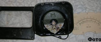
An example of a modern resistance meter is the Vitok ohmmeter, which has a combined power supply.
Ammeters
An ammeter measures electric current, and its name comes from the unit of measurement - Ampere. In order for the device to detect current, it must be connected in series. This is important because objects in a series circuit experience a single current. They do not have to be connected to a voltage source - ammeters operate at minimal load. You can look at the ammeter circuit.
An ammeter is installed in series connection to determine the current. All current in the circuit passes through the meter. If the ammeter is between points d and e or f and a, it will acquire the same value
Design of a multi-range voltmeter
Our simple DC voltmeter described above can be expanded by using a number of series resistances, each rated for a specific voltage range, which can be selected one at a time using a single multi-pole switch, allowing our analog voltmeter to measure a wider range of voltage levels in one move .
This type of voltmeter configuration is called a multi-range voltmeter, where ranges are selected based on the number of switch positions, such as 4-position, 5-position, etc.
Voltage measurement
When electric charges are in equilibrium, the voltage between any two points in a circuit is zero, but if current flows through the circuit (charge movement), then a voltage will exist between two or more different points in the circuit.
Using a galvanometer, we can measure not only the current flowing between two points, but also the voltage difference between them, according to Ohm's law, since these quantities are proportional to each other. Thus, using a graduated voltmeter, we can measure the potential difference between any two points in a circuit.
But how do you convert a device that handles current into one that can be used to measure voltage? The deflection of a permanent magnet moving coil meter is proportional to the current passing through its moving coil.
If its full-scale deviation (FSD) is multiplied by the internal resistance of the moving coil, the meter can be made to read voltage instead of current, thus turning a permanent magnet moving coil meter into a DC voltmeter.
However, due to the moving coil design, most PMMC meters are very sensitive instruments that can have full-scale deflection current IG ratings as low as 100 µA (or less). If, for example, the resistance of the moving coil RG is 500Ω, then the maximum full-scale voltage we could measure is only 50mV (V = I*R = 100µA x 500Ω).
Therefore, in order for the sensitive moving coil of a PMMC voltmeter to measure higher voltage values, we need to find a way to reduce the voltage being measured to a value that the meter can withstand, and this is achieved by installing a resistor called a multiplier in series with the internal resistance of the meter coil.
Let's say we want to use our 100 µA, 500 ohm galvanometer to measure voltage in a circuit up to 1.0 volts. Obviously, we cannot connect the meter directly to measure 1 volt because, as we saw earlier, the maximum voltage it can measure is 50 millivolts (50 mV). But, using Ohm's law, we can calculate the value of the series resistor RS that is needed to obtain full-scale motion of the meter when measuring a potential difference of one volt.
Thus, if the current at which the galvanometer gives full scale deflection is 100 µA, then the required series resistance RS is calculated as 9.5 kΩ. Thus, a galvanometer can be converted into a voltmeter by simply connecting a sufficiently large resistance in series with it, as shown in the figure.
How to measure resistance by direct assessment?
Direct assessment method
involves
measuring DC resistance
using an ohmmeter.
An ohmmeter is a direct
for determining electrical active (active resistances are also called ohmic resistances) resistances.
Interesting materials:
How to determine the meiza model? How to determine the processor model in a smartphone? How to determine the Nvidia video card model? How to determine the mode of a variation series? How to determine the wet zone? How to identify a coin MMD or LMD? How to identify a coin from the Moscow Mint? How to identify the monitor on a computer? How to define morality? How to determine sea or lake?