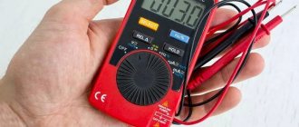
A multimeter is a device for changing a number of electrical parameters. Often in everyday life there is a need to use a multimeter, but not everyone knows how to do it. As a result, all work is left for later, and new equipment is sent to a landfill due to the inability to detect a defect. With the help of this article, even a beginner will learn how to use the device correctly.
Digital multimeter
Digital multimeters have almost replaced analog multimeters due to their cheapness, convenience, and multitasking. Therefore, in this article we will talk specifically about digital multimeters and their functions.
A digital multimeter consists of a display, a function selection switch (I just call it a knob), sockets where probes are inserted, and the probes themselves.
With cheap multimeters, when measuring any value, you need to select the range to be measured, therefore, you can often see numbers such as 2, 20, 200, and so on, which indicate the maximum measurement range.
Features of Chinese multimeters
When visiting Chinese online trading sites, your eyes widen at the variety of devices. It seems that the characteristics are the same, but the names and prices are different. I hope it won’t be a revelation to anyone that almost all multimeters are manufactured at one factory, and brands are ordered by trading organizations.
However, the accuracy of the devices is decent - the error is less than 1%. This is normal even for European models.
Most multimeters are powered by AAA batteries rather than Krona batteries, which have a shorter cell life. Even inexpensive models are equipped with display backlighting, which is important for installers.
Well, as a rule, the price for them is not high, so if they are used harshly, it is not a shame to replace them. But, regardless of the price, installers’ devices last for several years in harsh conditions, even with a broken case.
Instructions for the multimeter
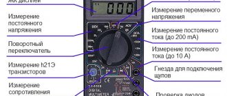
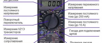
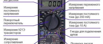
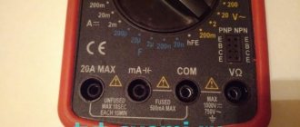
On the front part we see a switch with which we can select the functions we need. Let's look at the symbols that are on the multimeter. I marked each function with a number for ease of perception.
1) Resistance Ω. This icon tells us that we are going to measure the resistance of some conductor or resistor.
2) Constant voltage =V. By setting the switch to this icon, we can measure DC voltage.
3) AC voltage ~V. With this function we can measure the value of AC voltage.
4) Measurement of the gain of hFe transistors. I don’t use it, because I have a transistormeter special for this purpose. You can read more about the gain in this article.
5) Capacitor capacity F. Everything is obvious. Capacitance can be measured.
6) DC voltage current measurement =A. We can measure the current strength of direct voltage.
7) Measurement of AC voltage current ~A. With this function we can measure the current of AC voltage. For example, this function is useful when we need to find out how much current flows in the circuit when we connect an incandescent lamp or some other load to a 220 Volt network.
8) Diode continuity test and continuity test of conductors. Shows resistance if you measure the integrity of conductors. When checking diodes, it shows the voltage drop across the PN junction. The beauty of this function is that if a resistance of less than 100 Ohms is displayed (it is different for different models), a screaming signal is heard from the multimeter. A very convenient function for checking diodes, as well as the integrity of wires and fuses. If you buy a multimeter, be sure to buy one with a diode tester, otherwise such a multimeter will suddenly lose its functionality.
Multimeter and resistance
To find out the resistance of any radio component, use a conventional multimeter. Measurement algorithm:
- Insert the probes (black – into the “COM” socket, red – into the socket marked “V/Ω” or “VΩmA”).
- The switch will need to be moved to the “Ω” position.
- At the third stage, it is advisable to check the serviceability of the device by connecting the two remaining free ends of the probes. The multimeter is working if it shows a zero value.
- Set the measurement limit to the expected approximate average value (for example, 2 M).
- Connect electrical probes to the coil (to the measurement object).
What will be the coil resistance? Source cdn.sparkfun.com
- Look at the display (screen) of the device.
If several zeros appear, the coil has resistance, but the measurement limit will need to be lowered slightly to see the actual digital resistance value. The same must be done when a number appears in front of the numerical value on the electronic multimeter, but with a zero (zeros) at the beginning. If a unit occurs, it is worthwhile, on the contrary, to reduce the set denomination.
How to check voltage with a multimeter
DC voltage measurement
As you know, there are two types of voltage: alternating and constant. Any multimeter has at its disposal the functions of measuring direct and alternating voltage. To measure the voltage, we must touch the leads of the power supply with the probes. As you can see, it is advisable to connect the minus of the power supply to the minus of the multimeter (COM-black probe), and the plus to the red probe of the multimeter.
measuring DC voltage using a multimeter
In order to measure DC voltage, we must set the switch to the “=V” icon or similar. Let's measure the voltage on the battery, since the battery produces a constant voltage.
To do this, set the switch on the multimeter to measure DC voltage. For a more accurate measurement, I set the range to 20 Volts. We touch the battery with the probes and look at the value on the display. 1.28 Volts, which is considered normal for a nickel-manganese battery.
In order to measure the voltage on any chemical current source, we simply set the range we need, then make sure that the probes are in their places (black on COM, red on V) and then touch the terminals of the battery, accumulator or any other current source.
Here, for example, I measure the voltage on a car battery.
You can also measure the voltage from a laboratory power supply that produces direct current. Let's demonstrate what it all looks like. I set the voltage on the power supply to 10 Volts and measure this voltage with a multimeter.
measuring DC voltage from the power supply
But what happens if we reverse the polarity? That is, we connect the red probe of the multimeter to the minus, and the black probe to the plus? The digital multimeter in this case will simply show a minus sign.
In modern multimeters, this icon is already combined with the AC icon and looks like this:
combined icon of direct and alternating voltage Here, using the function key, we ourselves choose what current we will measure: direct or alternating. Direct current is designated DC - direct current, which literally translated from English is “direct current”.
function switching key
In the example below, I measured the voltage on a lithium-ion battery.
AC voltage measurement
To check the alternating voltage, we must set the functionality selection switch to the “~V” icon. I think you are aware that the voltage in the outlets in your home is variable. Let's measure its value. As you can see, the multimeter showed 215 Volts, although it should be something around 220 Volts. This voltage is still within the operating range, so everything is fine.
For a multimeter with automatic range measurement, we need to select the AC icon on the display of your device using the FUNC key. AC - alternating current, which literally translated into English is alternating current.
This is how the voltage in an outlet is measured. 228 Volts, which is also quite normal.
Video description
Learn how to quickly check a car battery with a multimeter in this video:
Checking a car battery using a multimeter Source mobilehomepartsstore.com
Further measurements will be made in the same way. To measure the current strength in the wiring of your car or for a separate electrical appliance, you should first find out what kind of current you need to check (for example, the “DCA” marking indicates constant). To measure resistance, set the toggle switch to any position, and do not forget to turn off the power to the network.
How to measure current with a multimeter
Measuring current in a DC circuit
In order to measure the current in a circuit, we must connect a multimeter to the open circuit.
On simple digital multimeters, you need to transfer the red probe to socket A or mA, which means Amperes. You haven't forgotten that current is measured in Amperes, right?
In order to measure the current in a DC circuit , we must set the switch to “=A”. So, in our case, we will supply voltage from the power supply to the computer fan.
We assemble this whole thing according to our scheme, but instead of an incandescent lamp we will have this fan.
Since my power supply already has a built-in ammeter, I can compare the readings on the multimeter and on the power supply. As you can see, they are completely identical. The current value in the circuit is 0.18 Amperes.
On a cooler multimeter we display one of these icons.
If you don’t know at all what approximate current strength should be in your circuit, then always set the switch to the highest range. In this case, at A. Let's check the current consumed by a 12-volt incandescent lamp. To do this, set the voltage on the power supply to 12 Volts and place a multimeter in the open circuit. That is, we do everything as it is according to this scheme.
As you can see, the current in the circuit is 0.707 Amperes. This means that an incandescent lamp at 12 Volts consumes a current of 0.707 Amps.
measuring DC current using a multimeter
Measuring current in an AC circuit
In order to measure the current in an AC circuit, we need to set the switch to the “~A” icon. In cool multimeters we put the function switch on one of these icons
and then we select using the “AC” function key, which indicates that we are going to measure the current in an alternating current circuit.
In order to demonstrate this, I will need a laboratory autotransformer (LATR).
laboratory autotransformer
This autotransformer allows you to obtain an alternating voltage of a lower value than in a 220 Volt home network. I set the voltage at the LATR output to 12 Volts. Don't forget that these 12 volts are alternating voltage. I connect the whole thing using the same scheme. By the way, the incandescent lamp here is more powerful, therefore, it will consume more current.
Appearance of the multimeter
A multimeter is a universal device for measuring electrical characteristics that combines many functions (depending on the model). In the minimum configuration, such a device consists of an ammeter, voltmeter and ohmmeter. In the most common version, it is performed digitally and portable. Externally it has a rectangular shape with a display and a rotary or push-button function switch. To perform measurements, two probes (red and black) are connected to the multimeter in strict accordance with the markings on the device.
Brief description of the measured parameters and their designation
Manufacturers use standard markings in English or special symbols to indicate parameters on multimeters. To operate the device, it is important to know the basics of electrical engineering in order to correctly and safely carry out the necessary measurements.
Each device is divided into zones with settings for working with a certain type of electrical network voltage:
- ACV or V~ – alternating current voltage;
- DCV or V- – DC voltage;
- DCA or A- – direct current strength;
- Ω is the resistance in a section of a circuit or in an electrical device.
Purpose of connectors for connecting probes
Depending on the multimeter model, the number of sockets for connecting probes may vary. It is necessary to connect the probes for measuring the electrical parameters of the network into the correct sockets of the device. For most measuring instruments, the sockets are marked as follows:
- 10A- – for measuring direct current not exceeding 10 A (a red positive probe is connected to this socket);
- VΩmA or VΩ, V/Ω - a red (positive) probe is connected to this socket when determining voltage, direct current up to 200 mA, for continuity testing of diodes and circuits;
- COMMOM (COM) – common socket for the black (negative) probe on all types of multimeters;
- 20A - such a socket does not exist on all models (most often it can be found on expensive professional devices), the task of this socket is similar to 10A-, but with a limit of up to 20 A.
How to test a capacitor with a multimeter
In order to check the integrity of the capacitor with a multimeter, its capacitance must be 1 µF or higher. This trick only works with analog multimeters, as well as with digital range selecting multimeters, such as these.
As you know, capacitors are polar and non-polar. Read more here. Polar capacitors have a large capacity, so they are easier to check for functionality. How to do this? Let's take a look at the example below.
We have an electrolytic capacitor.
We set the multimeter to the continuity mode and touch the leads of the capacitor with the probes. We carefully watch the numbers on the scoreboard. They should increase as the capacitor charges.
As soon as I touched the leads, the multimeter immediately showed this value
in half a second
and then the value went out of range, and the multimeter showed one.
So what can we say? At the very initial moment of time, a completely discharged capacitor behaves like a conductor. As it is charged with current from the multimeter, its resistance increases until it becomes very high. Once the capacitor is charged, it means it is working. Everything is logical.
Capacitors of smaller capacity and non-polar capacitors can be tested using a tester only for a short circuit between its plates. Therefore, a different iron method is used here. Just measure the capacitance of the capacitor). Here I measured the capacitance of the capacitor, on which 47 uF was written. The multimeter showed 48 uF. Either the error of the capacitor or the multimeter. Since Mastech multimeters are considered to be quite good, we will attribute it to the capacitor error).
How to connect wires to a multimeter
Let's look at connecting electrical wires to the meter. Such wires are called probes. A probe is an electrical wire with a metal tip at the end and a plastic current-protective sheath.
Main connectors for probes:
- The black wire is considered zero, negative, grounding. Connects to the connector marked “COM”.
- To measure current less than 200 mA, there is a connector marked “VΩmA”. It is better not to try to measure a current strength of a higher value - either the fuse or the multimeter itself will not withstand it.
- Connectors for measuring high currents are designated “10 ADC”. This means that the tester is capable of measuring current from 200 mA to 10 A. The number may be different - it shows the measurement limit.
How to measure resistance with a multimeter
So, we have everyone's favorite digital multimeter
In order to measure resistance, we need to turn the function selection switch to “resistance measurement”. This is our entire top row in green with the letter Ω. The letter “K” tells us that we are going to measure kilo-ohms, and the letter “M” means that we are going to measure mega-ohms. The measurement limit is shown before the letter. If a 1 lights up on the multimeter display when measuring resistance, then we switch to a higher limit.
How to test a fixed resistor
So, we have this resistor.
We see the inscription “82R” on it. It means that its resistance should be 82 Ohms. You can read more about resistor markings in this article. To do this, apply one probe to one end of the resistor, and the other probe to the other end.
As you can see, the multimeter almost accurately showed the resistance value of this resistor.
How to test a variable resistor
Let's measure the resistance of the variable resistor. As you know, with a variable resistor we can change the resistance manually. The same applies to tuning resistors - this is one of the types of variable resistors.
This is his view from below. Here we see the inscription 47 KM. This means its resistance should be 47 KiloOhms between the two extreme contacts.
Using the handle, we can turn it clockwise or counterclockwise, thereby changing the resistance between the middle contact and the two outer contacts
Here is its schematic designation:
We place the probes at the extreme contacts. We measure the total resistance of the variable resistor.
Hmmm... A little different resistance. Our variable resistor is too old, which may be why its resistance does not match what is written on it. In order to check whether it is working, turn the variable resistor knob all the way counterclockwise and measure the resistance between the left and middle contacts. It should be close to zero.
Turn the handle clockwise, but not all the way. We measure the resistance between the middle and left contacts again.
We measure the resistance between the middle and right contacts.
The total should be the result of the resistance of the two extreme contacts. 12.2+27.6=39.8 Almost everything is correct. Therefore, our variable resistor is working properly.
Rules for measuring resistance
- Press the probes with some force onto the resistor terminals. In this way, you will eliminate the appearance of contact resistance, which, when pressed lightly, will add up to the measured resistance.
- Do not measure resistance under voltage! This could damage the multimeter or cause you an electric shock!
- When measuring the resistance of a resistor on a printed circuit board, double-check that the board is de-energized. Then unsolder one end of the resistor and then measure its resistance.
- Do not touch the resistor leads when measuring its resistance! The average human body has a resistance of about 1 KiloOhm and depends on many factors. Therefore, by touching the resistor terminals when measuring resistance, you introduce an error into the measurements.
- If you want to measure the resistor's resistance as accurately as possible, clean its terminals either with a knife or with the mildest sandpaper. In this case, you will remove the oxide layer, which in some cases introduces a noticeable error in the resistance measurement.
How to set up a multimeter
Let's look at how to properly use a digital multimeter for dummies. After turning on the device, move the knob selector to the desired measurement sector - voltage, current, ohmmeter, temperature, ringing or others. Knowing the approximate parameters of the measured quantities, we set a larger value in the sector. If the value is incorrectly selected, when measuring the voltage, 1 will appear in the most significant digit. This will indicate infinite voltage. The pointer tester will simply go off scale and point the needle point blank. If we don’t know the value of the parameter being measured in advance, then we set the highest value and touch it with the probes. If the value on the screen is lower than the next segment limit, then turn the knob to a lower value. In analog, this process is repeated if the needle reacts somehow, almost without deviating from zero.
Detailed instructions for using the tseshka come with each copy. It is important to learn how to work with the device that you have, because the differences are sometimes significant.
How to make calls with a multimeter
All modern digital multimeters have a dialing function.
Continuity testing is the same “resistance measurement” function, but only in this case the multimeter makes a squeak if the resistance is less than 100 Ohms. Why is this function needed? In order to check the integrity of wires, fuses, incandescent lamps, printed conductors, and so on. A very convenient and indispensable function in any multimeter. Most often, the continuity icon is combined with a diode continuity indicator. It all looks something like this:
diode continuity
For example, I want to ring a light bulb and find out if it is intact? To do this, I put the switch on the corresponding icon and touch the lamp with the probes. The multimeter emits a heart-rending “piiiiip” sound, and the display of the multimeter shows the filament resistance reading. This means that the light bulb is alive, since the tungsten filament is not broken.
continuity test with a multimeter
Testing with a multimeter
The multimeter has several more functions, one of which is the so-called continuity test. It is used to search for a break in the neutral wire in an electrical circuit.
Algori:
- connect the red probe to “V/Ω”, the black one to “COM”;
Testing wires with a multimeter to check their integrity Source avatars.mds.yandex.net
Proven Multimeters
With my many years of experience in the field of electronics, I have changed many multimeters. I would like to focus on two brands that made me very happy and still make me happy in my difficult task.
Multimeters DT9205
Large display, convenient functionality, automatic shutdown function, inexpensive cost. If you look through the pages of my website, you will see that I used exactly these models of multimeters in my practice. They are very comfortable and durable. Yes, they are large, but it's worth it. This multimeter fits very comfortably in your hand.
Here is the link to Aliexpress. Try to take exactly the same one as in the photo above. Its cost is in the range of 700-800 rubles.
Setting up the multimeter
First, you need to set up the multimeter to work.
Probe connectors
Multimeters have 3 to 4 probe connectors. In 90% of measurements, only two connectors will be needed. These are COM and VΩ.
The black probe of the multimeter is always connected to COM. The default black probe is negative, the common wire. That's why it's called COM.
To measure voltage, resistance or continuity of radio components, the red probe is connected to the VΩ connector.
Where is the plus on the millimeter?
By default, the positive wire is the red wire if you have it connected correctly. The black probe of a multimeter is always a minus, and it is inserted into the COM connector regardless of the operating mode.
Calling
What does it mean to ring with a multimeter? This term appeared back in the days of using pointer testers, when it was necessary to check an electrical circuit for resistance. In order to set the instrument scale to zero, and also to make sure that the probes were in good condition, they were connected to each other. In this case, the switch was installed in the sector on which a bell was drawn. If everything was in order, then the bell rang.
Therefore, when the question is asked how to test a circuit, or how to test a wire with a multimeter, you need to understand that this is just an analogy.
Everything that was described above is actually a few simple operations. But they help novice electricians navigate the problems of electrical circuits. It is they who, at the beginning of their work, begin to wonder how best to use a multimeter tester. All answers are in this article.
If you find an error, please select a piece of text and press Ctrl+Enter.
Additional features
Due to the ability to measure electrical current parameters, multimeters are used to check the integrity and serviceability of individual circuit elements. An electrical measuring device is used to check batteries, accumulators and capacitors. With its help, the neutral and phase wires are determined.
Capacitor check
A multimeter is used to check polar and non-polar capacitors with a capacity of 25 µFarads or more. Polar method:
- Solder the capacitor from the circuit;
- Identify negative and positive contact. A minus is usually indicated by a daw on the body, as in the figure below;
- Use tweezers to close the contacts for complete discharge. You can check the capacitor with a multimeter without desoldering it. But are you sure that it is discharged? The results of the check will depend on this. Be sure to unsolder at least one contact;
- Then turn on the resistance measurement mode by connecting the probes accordingly;
- Touch the black probe to the negative pole of the capacitor, and the red probe to the positive pole;
- At first the resistance will be small, then it will increase. And so on until the scale overflows (in the figure the display shows the “1” sign). This indicates that the capacitor is working properly. If the resistance is zero or the resistance goes off scale immediately without increasing the resistance, then the element has failed and must be disposed of.
Is the battery still working?
All the batteries were mixed: both new and old. It is not necessary to insert each one into a remote control or other device to check operation. You can use a multimeter:
- Set the switch to measure a constant current of 10 A;
- Insert the black probe into the “COM” connector, and the red probe into 10 A;
- Then touch the positive pole of the battery with the red probe and the black pole with the negative one;
- Hold the probes for no more than 1-2 seconds, otherwise overheating will occur, which is harmful to the batteries.
If the current is more than 4 Amperes, then the battery is new and can serve for a long time in portable equipment. From 3 to 4 – it will last less, but it can be used. For remote controls, 1 Ampere is enough, and from 0.7 Ampere, malfunctions will already be observed. If the current is less than 0.7 Ampere, discard the battery. It can no longer be used anywhere.
Checking the battery in the car
Checking your car battery with a multimeter gives you an idea of whether it has a charge. By measuring the voltage at the terminals, you can conclude whether charging is required or not. For check:
- Insert a black probe into the “COM” connector, and a red probe into the port for measuring voltage;
- Set the range to 20 Volts in the “constant voltage” (DCV) measurement mode;
- Touch the negative terminal of the car battery with the black probe, and the positive terminal with the red one;
- Record the value that appears on the multimeter display.
Compare the results with the table below.
| Voltmeter readings, V | Battery charge level |
| From 12.6 to 12.9 | 1 |
| From 12.3 to 12.6 | 0,75 |
| From 12.1 to 12.3 | 0,50 |
| From 11.8 to 12.1 | 0,25 |
| From 11.5 to 11.8 | 0 |
Electrical continuity check
Using a dialer, they check whether two points are connected. How to test the wires with a multimeter and see if there is a break between them? For this:
- Connect the black probe to the common port, and the red probe to the one marked with the Ω symbol;
- Turn on dialing mode;
- Disconnect the part of the circuit being tested from the power source;
- Use the probes to touch the points of interest;
- If there is a sound signal, the dots are connected. If it is not there, the chain between the points is broken.
Let's show with an example how to ring a heating element with a multimeter:
- Connect the probes and turn on the resistance measurement mode up to 200 Ohms;
- Apply the ends of the probes to the terminals of the heating element and measure the resistance;
- Compare the reading with the calculated resistance calculated using the formula R=U2/P (voltage squared divided by the power of the device, and voltage equals 220). For example, power is 1500 W, then R = 32.2 Ohm.
If the resistance goes off scale, then there is a break inside the heating element. If it shows zero, then there is a short circuit inside. And if it is close to the calculated value, the heating element is in working condition. But in this case, you need to check if there is a leak. To do this, check the heating element again, but in dialing mode. But touch the body with the black probe, not the terminal. If there is no sound signal, the heating element is working; if there is a squeak, the insulation is broken and a leak occurs.
Finding phase and zero
When connecting electrical devices, it is important to know where the phase is and where the zero is, the ground. Details on how to determine phase and zero with a multimeter are written in the instructions:
- Set the multimeter to ACV mode and set the limit to 250 volts;
- Three different pairs can be made from three cables: phase and neutral, neutral and ground, ground and phase. Touch the multimeter probes to each pair of wires;
- In two cases there will be tension, but in one there will not be. The pair in which you did not detect voltage is zero and ground. Bend them to isolate the third cable, which is the phase;
- To check grounding and zero, measure the voltage paired with the phase with each of the bent wires;
- The ground will be the wire where the voltage is minimal. Therefore, the remaining wire is common (zero).
A multimeter is an affordable device for making electrical measurements. It makes it possible not only to measure the parameters of the electrical circuit, but also to diagnose the serviceability of its elements. And professional instruments are endowed with special functions, which makes multimeters universal electrical measuring instruments.
What can you measure with a multimeter?
This option allows you to check:
— lighting elements (light bulb, wiring, socket);
— various types of cables (electrical, audio, network);
— heating and other electrical appliances;
— batteries (battery, adapter, accumulator);
- electronic device boards and much more.
In complex cases, for example, with electronic boards or multi-core wires, in addition to knowledge and experience, it is necessary to rely on wiring diagrams specific to each specific device. They can be found either in the technical documentation accompanying the purchase or on the Internet.
Decoding the symbols 20k and 20m on a multimeter
Next to the numbers indicating the measurement range, you can see letters such as µ, m, k, M. These are so-called prefixes, which indicate the multiplicity and fractionality of units of measurement.
- 1µ (micro) – (1*10-6 = 0.000001 from unit);
- 1m (millies) – (1*10-3 = 0.001 from unit);
- 1k (kilo) – (1*103 = 1000 units);
- 1M (mega) – (1*106 = 1,000,000 units);
For example, to check the same heating elements, it is better to take a tester with a megometer function. I had a case where a malfunction of the heating element in a dishwasher was detected only by this function. For radio amateurs, of course, more complex devices are suitable - with the function of measuring frequencies, capacitor capacity, and so on. Nowadays there is a very large selection of these devices; the Chinese don’t do anything.
Author of the publication
offline 1 year
Measuring battery voltage
Voltage is much easier to measure than current. Because you don't need to bother with the load. We turn on the multimeter in parallel. That is, we simply connect the red probe to the positive input, and the black probe to the negative input. But before that, you need to move the selector to the measurement limit closest to the top. Middle one from above: for a car battery it will be 20 volts, for small batteries - 10, if there is such a limit on the scale. Now you can touch the battery terminals with the probes - black for minus, red for plus.
How to use a multimeter
Details Category: Beginners Published 09/13/2016 08:48 Author: Admin
A multimeter is a miniature device designed for measuring various electrical parameters, as well as for testing semiconductor devices and electronic components. Roughly speaking, a multimeter is the same measuring instrument as a ruler or, for example, a scale, only it measures not centimeters and grams, but Ohms, Volts and Amperes. By the way, the prefix “multi” indicates that it can measure several quantities.
- Multimeter capabilities
- Voltage, current, resistance
- Direct and alternating current
- Parallel and serial connection
- Symbols on the front panel of the multimeter
- Symbols on the multimeter and their purpose
- Voltage measurement
- Current measurement
- Resistance measurement
- Chain continuity
- Diode check
The appearance of the device is shown in the photograph. As you can see, there is a large switch installed on its front panel. It is used to select a parameter, as well as the measurement limit. In addition, the multimeter has a liquid crystal display on which the measurement result is displayed. This article will discuss how to use a multimeter
To be fair, it is worth noting that the multimeter does not necessarily have a liquid crystal display. There are still many outdated models on the market that have a dial scale. And although these devices do not have the same accuracy as digital ones, and they are not as convenient to use, many radio amateurs prefer them. And yet, in this article we will talk specifically about devices with liquid crystal display.
Multimeter capabilities
All multimeters, without exception, allow you to measure voltage, current and resistance. These values will be discussed in more detail below. In addition, most devices are equipped with a circuit probe; some multimeters have the ability to measure temperature. The circuit tester allows you to quickly determine the integrity of the conductor. If the circuit resistance is less than 30 ohms, a sound signal will sound. This is very convenient - there is no need to look at the indication, and the resistance value is not so important when checking an elementary circuit.
Another useful function of multimeters is testing semiconductor diodes. Anyone who has worked with them knows that a diode passes current in one direction. If there is conductivity in the other one, then the device is faulty. The multimeter analyzes these parameters and displays the result on the screen. In addition, in the case where there is no marking on the diode body, its polarity can be easily determined using a tester. Unfortunately, not all multimeters have this function.
More expensive and advanced models of devices have the ability to measure quantities such as the inductance of coils and the capacitance of capacitors. But since only special multimeters can do this, they will not be considered in this article.
Voltage, current, resistance
In this section, a small educational program for those who were not previously familiar with these quantities. It is immediately worth noting that special quantities have been invented to measure them. If we draw an analogy with distance, it will be measured in meters and denoted by the English letter “m”. Exactly the same abbreviations were invented for electrical quantities.
Voltage is the force that causes current to flow through a conductor. The higher the voltage, the faster the electrons move. Voltage is usually measured in volts, abbreviated to the capital letter “V”. But since it is impossible to find a multimeter with a Russified front panel on the market, you need to look for the English “V” on it.
The intensity of current flow through an electrical circuit is determined by its strength. Here it is appropriate to use a plumbing analogy to imagine an electrical circuit in the form of a pipe filled with water. High pressure in this pipe is not a reason for water to flow through it. The valve may simply be closed at the other end of the pipe. And as it opens, the flow rate will increase. This speed, in an electrical circuit, will be the current strength. It is measured in amperes "A".
Resistance shows how difficult it is for current to pass through a particular section of an electrical circuit. Returning to the plumbing allegory, resistance can be compared to some narrow section of a pipe, such as a blockage. The smaller the diameter of the pipe in this place (read more resistance), the lower the speed of water flow (current strength). This is very well illustrated in the funny picture. The unit of measurement is the ohm, which is denoted by the Greek letter omega (?).
Direct and alternating current
Direct current – for those who know English, translation will not be difficult. Literal translation, directional current. This is an electric current that flows in one direction. In Russian it is called permanent. Most small household appliances operate on direct current. It is issued by batteries of all classes and sizes, car and telephone batteries. Direct current is given the abbreviation DC.
Depending on the manufacturer, the corresponding positions on the multimeter can be designated either DCA and DCV (measurement of direct current and voltage, respectively), or “A” and “V”, with a line next to it and a dotted line below it.
Alternating current changes its direction dozens of times per second. For example, in home sockets the frequency is 50 hertz. This means that the direction of the current changes 50 times per second. But you shouldn’t try to measure high voltage in an outlet without experience and safety knowledge. It is very dangerous.
Alternating current received the abbreviation “AC”. There are 2 options available on the multimeter switches: “ ACA ” and “ ACV ” for measuring alternating current and voltage; A ~ and V~.
Measuring DC voltage has its own nuances - polarity must be observed. This is especially true for pointer instruments. In this case, their measuring head may fail. Digital ones endure it painlessly, just a minus sign appears on the screen. This must be taken into account before using the multimeter in voltage measurement mode.
Parallel and serial connection
When working with a multimeter, it is very important to know how to connect it when taking measurements. There are only two options: in series or in parallel, depending on what value needs to be measured. When connected in series, the same current flows through all elements of the circuit. Therefore, sequentially, they also say “into an open circuit,” you need to measure the current strength. If we consider a parallel connection, then the same voltage is applied to each element, and by placing probes parallel to any of them, you can measure it. So, voltage is measured in parallel, current is measured in series, this must be remembered and never confused.
The figure shows parallel and serial connection diagrams. It should be noted that when in series, the current flowing through each of the elements will be the same if their resistances are equal. The same condition will ensure equal voltage across the elements in the case of a parallel connection.
Symbols on the front panel of the multimeter
Not an experienced user, tricky symbols printed on the main switch of the multimeter. But there is nothing complicated here, you just need to remember how the units of measurement of voltage, current and resistance are designated:
- Volt – “V”;
- Ampere – “A”;
- OM – “Ω”
All manufacturers, without exception, use only these icons. True, there is one thing. It is not always necessary to measure whole quantities. Sometimes the result is thousandths of a unit of measurement, and sometimes, on the contrary, millions. Therefore, the corresponding measurement limits are included in the multimeter and manufacturers use metric prefixes to designate them. There are only four main ones:
- µ (micro) – 10-6 units of measurement;
- m (miles) - 10-3 units of measurement;
- k (kilo) – 103 units of measurement;
- M (mega) – 106 units of measurement.
These prefixes are added to the basic units of measurement and in this form are applied to the device operating mode switch: µA (microampere), mV (millivolt), kOhm (kilo-ohm), mOhm (megaohm).
Before measuring any value, you need to set the appropriate limit. To do this, you need to at least approximately know what the result will be, and set a number on the device that is slightly higher than it. If even to a first approximation it is impossible to predict the magnitude of the measured current or voltage, it is better to start with the maximum limit. The result obtained will be very approximate, but will allow you to draw a conclusion about what limit to set. Now measurements can be taken with greater accuracy.
Some multimeters are equipped with an “auto-rangin” function. Thanks to it, the measurement limit is set automatically. This is very convenient, since using a multimeter in this case is much easier. The figure shows a simple multimeter (on the left) and a device equipped with the auto-ranging function (on the right).
Symbols on the multimeter and their purpose
Instrument manufacturers rarely, if ever, adhere to standards, so different multimeters may label the same function differently. Of course, it is impossible to list all possible symbol options here, but the main ones are given below.
Like this, the wavy line represents alternating current. Please note that both current and voltage can be measured. It can be alternating current (current strength), or it can be alternating current voltage.
A horizontal line with a dotted line below it indicates constant current and constant voltage.
Designation of current and voltage using the abbreviations “AC” and “DC”. The example shows that sometimes letters are duplicated by signs. It should also be noted that the designations AC, DC can be either before or after A or V.
This icon indicates continuity of the circuits. If the circuit is intact, the multimeter will beep. Sometimes this function is combined with the resistance measurement mode. In this case, the beep will sound if the resistance is less than 30 ohms.
Diode test function. Allows you to determine the health of the diode and its polarity.
What. We can consider the theoretical part finished. Now you can proceed directly to the measurement process.
Voltage measurement
to measure voltage you need:
- connect the probes to the multimeter.
- It’s better to get used to doing it correctly right away: black to the COM , and red to the V ;
- set the switch to the position corresponding to the measurement mode (variable or constant) and the limit;
- Now you can place the probes parallel to the circuit element on which you are supposed to measure the voltage.
The figure shows an example of measuring the voltage drop across a nine-volt “crown” battery;
The device screen should now show voltage. If “1” appears on the display, the measurement limit is small, you need to set it lower. But in this example the switch is in the correct position, set to the 20 Volt DC limit. The red wire is positive, connected to the positive of the battery, and the black wire is negative, inserted into the COM on the multimeter. It connects to the negative of the battery.
Current measurement
We connect the probes, do not forget about the color; Here you need to pay attention to the following: when measuring small currents, the red cord is connected to the same socket as when measuring voltage, and for currents up to 10 amperes - to the “10A” connector. Now you need to select the measurement mode and its limit.
Unlike voltage, current is measured sequentially. To do this, you will have to break (that’s why they say “break”) the chain. If everything is done correctly, the display will show the current value. In the case when zeros are displayed on the screen, there may be several reasons: the voltage is not turned on, there is no contact on the probes and, most likely, the limit is too high. If one is displayed on the screen, the limit is small. The figure shows a diagram for measuring direct current flowing through a light bulb.
Resistance measurement
Connect the probe to the “COM” and “?” connectors. Of course, it is not necessary to observe polarity here, but it is still better to connect black to the COM connector. We set the limit and measurement mode.
We measure the resistance of the resistor or the light bulb spiral, as shown in the figure. It is imperative to keep in mind that the element being measured must be excluded from the diagram. Otherwise, the measurements will not be correct. If the indicator shows several zeros in front of the number, the measurement limit has been set; for greater accuracy, it must be reduced. If the limit is small, the indicator will still show the same unit.
Chain continuity
Set the device to beep mode. The switches have a corresponding icon. It is also given as an example in the table above.
Install the probes into the sockets by analogy with measuring resistance. Measure the desired circuit element. If an electric current flows between the probes, i.e. it is working properly, a sound signal with a frequency of about 1 kHz should be heard. In this case, it is necessary to disconnect the power from the circuit. By the way, if there is no sound signal, then it is not at all necessary that it is faulty. Perhaps its normal resistance is greater than 30 ohms.
Diode check
A multimeter tests a diode by passing current through it and measuring the voltage drop across it. If you have some skill, you can even test bipolar transistors with the device. Sometimes semiconductor devices do not even need to be desoldered from the circuit. So, the sequence of actions is as follows.
The probes are connected in the same way as resistance measurements. The device switch is set to the diode measurement position. Most often this is an icon - a schematic designation of a diode. We measure the diode by touching its anode and cathode with probes. The device readings should be: for a silicon diode -500-700 mV, for a germanium diode - 200-300mV, a working LED should show 1.5-2 V.
Now we change the polarity on the diode. The device must show zeros, otherwise it is faulty. That, in general, is all that can be briefly told about working with a multimeter. Everything else will come with experience. The main thing is not to forget about safety and before using a multimeter, be sure to study the safety rules.
- < Back
- Forward >
Add a comment
Multimeter capabilities
An electrical measuring device helps to measure three main characteristics of current:
- Current strength (denoted by the letter I) , which displays information about the amount of charge passing through the conductor per unit time. To better understand, imagine a faucet with water flowing from it. The amount of water flowing out of it per second can be compared with the current strength in a conductor, measured in Amperes ;
- Voltage that helps push electricity through a wire. You can compare it with the water pressure in a tap: the higher it is, the more water will flow out of it in 1 second. This quantity is designated U and is measured in Volts ;
- Resistance (denoted R) is the factor that prevents electricity from passing through a wire. Comparable to a clogged faucet: the more debris there is, the less water flows through it, despite the fact that water pressure (electrical voltage) is pushing it. Resistance is measured in Ohms .
The picture below will help you visualize the relationship between current, voltage and resistance. But it has English designations for quantities - VOLT (Volt), AMP (Ampere) and OHM.
There are direct and alternating current:
- Direct current has one direction. It is found in circuits where the source is a battery or accumulator, in which constant current and constant voltage are measured;
- Alternating current changes its direction dozens of times per second. This current is present in the socket. However, even in such circuits the values of constant current and constant voltage are output.
Multitetra allows you to:
- Check the phase, find the neutral and grounding cable;
- Check the battery (is it working or can you throw it away);
- Find out whether the capacitor is in working condition;
- Check the integrity of the electrical circuit (if there is a suspicion that it has breaks).
Important! If you can measure Amps, Volts and Ohms with any multimeter, then ringing a wire or determining the capacitance of a capacitor will not work with any device. These are special functions that are not included in the basic set. Therefore, when choosing a device, pay attention to the availability of the options and measurement modes you need (not every device can measure variable quantities).
AC voltage measurement
How to measure AC voltage? The probes remain in the same position, the switch moves to the section (V~). There are also several measurement limits here. For example, how to measure the voltage in a 220 volt outlet with a multimeter. By the way, there is no polarity in alternating voltage, so the exact installation of the probes does not matter.
It is necessary to set the test level to more than 220 V, usually a switch from 600 to 750 volts, depending on the tester model. Now two probes are inserted into the socket. Depending on the load on the transformer, the result can vary from 180 to 240 volts. If the indicators fall within this range, then everything is fine.