Wiring type and its parameters
At home, you most often have to deal with alternating current, much less often with direct current.
Typically, direct current is measured in batteries and batteries; house wiring always runs on alternating current. Even if the electrical network is powered by batteries (a backup power source, the main one in the absence of a centralized power supply), it must contain an “adapter” - a device that converts direct current into alternating current. When figuring out how to measure current with a multimeter, you need to clearly understand: to work with direct current, use the DCA (A-) segment of the multimeter, for measuring alternating current, use the ACA (A~) sector. The designations are associated with abbreviations of English terms: direct current amperage (DCA) and alternating current amperage (ACA) is the designation of alternating current on a multimeter.
Typically, multimeters allow you to measure microcurrents - up to 200 mA - and stronger ones (up to 10A). Devices that allow measurements in more powerful electrical networks have an additional socket for a plug (probe) marked 20A. Typically, in models with four connectors, two are designed to measure current in different ranges, one is for other measurements (voltage, resistance).
The COM (COMMON) connector, common (universal) for all types of measurements, is intended for the negative (black) probe of the multimeter.
Thus, to measure current with a multimeter, you need to connect the black probe to the COM connector, and the red probe to the socket for checking microcurrents or ordinary currents. For sockets and switches, the device regulator is set to the alternating voltage sector, for batteries and batteries - constant. If the level is unknown in advance, the highest value allowed by the device is selected.
Important: if no energy-consuming device is connected to the outlet (on the switch), the electrical circuit is open and there is no current in it!!! Measuring the current directly in the socket or on the contacts of the switch is useless and dangerous! This causes a short circuit.
How to test a multimeter for functionality
- To check the functionality of the multimeter, as a rule, you need to perform the following steps:
- Set the probes to resistance test mode (R). In this case, the black wire should be inserted into the “COM” or “-” connector, and the red wire into the “Ohm” (Ω), or “omega” connector.
- Move the large dial pointer to the dial position.
- Align the metal ends of the probes with each other.
After these actions, a piercing sound signal should be heard. If there is no sound, then the multimeter is not working and is not even suitable for checking the wiring.
Why do you need to measure current?
The voltage and resistance of the electrical circuit, which are measured in units such as volts (V) and ohms, respectively, have a significant impact on the amount of current. In this case, an increase in voltage with a constant resistance of the electrical circuit causes an increase in current strength, and an increase in the resistance of the circuit with a constant voltage value leads to its decrease. Current (I), voltage (U) and resistance (R) depend on each other and are related by empirical formulas:
- I = U/R
- U = I*R
- R = U/I
In this case, it is simplified to assume that a current of 1 A appears in a conductor with a resistance of 1 Ohm if a voltage of 1 V is applied to it.
Current measurement
By measuring the CT with a multimeter, you can:
- clarify the actual power consumption of a particular electrical appliance;
- find defects in an electrical appliance if its actual power does not correspond to the value stated in the documentation;
- find out the electrical capacity of autonomous power sources (batteries, etc.);
- identify the existence of current leakage in electrical circuits and, if necessary, localize the defective area;
- check the battery charger to ensure that the charging current corresponds to the specified value, etc.
Such measurements are carried out using special instruments - ammeters. There are enough varieties of them on the domestic market to satisfy the needs of all buyers.
The most popular, especially at the household level, are small multifunctional (ammeter + ohmmeter + voltmeter) multimeters, with which you can measure almost all the necessary parameters of an electrical circuit.
Instructions for the multimeter
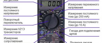
On the front part we see a switch with which we can select the functions we need. Let's look at the symbols that are on the multimeter. I marked each function with a number for ease of perception.
1) Resistance Ω. This icon tells us that we are going to measure the resistance of some conductor or resistor.
2) Constant voltage =V. By setting the switch to this icon, we can measure DC voltage.
3) AC voltage ~V. With this function we can measure the value of AC voltage.
4) Measurement of the gain of hFe transistors. I don’t use it, because I have a transistormeter special for this purpose. You can read more about the gain in this article.
5) Capacitor capacity F. Everything is obvious. Capacitance can be measured.
6) DC voltage current measurement =A. We can measure the current strength of direct voltage.
7) Measurement of AC voltage current ~A. With this function we can measure the current of AC voltage. For example, this function is useful when we need to find out how much current flows in the circuit when we connect an incandescent lamp or some other load to a 220 Volt network.
8) Diode continuity test and continuity test of conductors. Shows resistance if you measure the integrity of conductors. When checking diodes, it shows the voltage drop across the PN junction. The beauty of this function is that if a resistance of less than 100 Ohms is displayed (it is different for different models), a screaming signal is heard from the multimeter. A very convenient function for checking diodes, as well as the integrity of wires and fuses. If you buy a multimeter, be sure to buy one with a diode tester, otherwise such a multimeter will suddenly lose its functionality.
Digital multimeter
The most convenient is a multimeter, in which it is enough to simply set a specific measuring mode. There is no need to additionally specify the tolerance range, since the device itself adapts to the circuit parameters, takes measurements and produces the required result.
The image below shows the first position of the handle, which has several positions demonstrating AC and DC voltage. The first is indicated by V AC (~ symbol), the last DC (—), in the range of volts and millivolts. The current strength A is similar, not being divided into current types, but having a gradation in amperes and milliamps.
In addition, the function of measuring resistance and chain ringing is mandatory.
At the bottom there are several sockets used to activate the measurement wires. The socket marked with the second position COM is used for the main black wire. The third position shows the socket for making basic measurements using the red cord. The permissible limits for voltage and current measurements are shown below. The fourth socket, indicated by position 4 in the image, is used to measure current in amperes, with a maximum limit of no more than 10 A. All readings appear on the display with digital graphics, which is indicated by position 5.
A multitester with an indication of the measurement range is more common, primarily because it costs much less.
When using a multimeter, it is necessary to indicate both the operating mode and the alternating and constant currents. In the same sector, a switch is installed in the required measuring range, expressed in mA, µA and A. The example shown shows 4 socket connections. Two of them are for red wires, measuring up to 200 mA and up to 10 A. Voltage, resistance, capacitance and other indicators are measured using a separate socket.
External structure and functions
Recently, specialists and radio amateurs mainly use electronic models of multimeters. This does not mean that switches are not used at all. They are indispensable when electronic devices simply do not work due to strong interference. But in most cases we are dealing with digital models.
There are different modifications of these measuring instruments with different measurement accuracy and different functionality. There are automatic multimeters in which the switch has only a few positions - they select the nature of the measurement (voltage, resistance, current) and the device selects the measurement limits itself. There are models that can be connected to a computer. They transfer measurement data directly to a computer, where they can be saved.
Automatic multimeters have only types of measurements on the scale
But most home craftsmen use inexpensive models of the middle class of accuracy (with a bit resolution of 3.5, which ensures an accuracy of 1%). These are common multimeters dt 830, 831, 832, 833. 834, etc. The last number shows the “freshness” of the modification. Later models have wider functionality, but for home use these new features are not critical. Working with all these models is not much different, so we will talk in general about the techniques and procedures.
Structure of an electronic multimeter
Before using a multimeter, let's study its structure. Electronic models have a small liquid crystal screen on which measurement results are displayed. Below the screen there is a range switch. It rotates around its axis. The part on which the red dot or arrow is marked indicates the current type and range of measurements. There are marks around the switch that indicate the type of measurements and their range.
General structure of the multimeter
Below on the case there are sockets for connecting probes. Depending on the model, there are two or three sockets; there are always two probes. One is positive (red), the second negative is black. The black probe is always connected to a connector labeled “COM” or COMMON or that is labeled “ground.” Red - into one of the free slots. If there are always two connectors, no problems arise; if there are three sockets, you need to read the instructions for which measurements to insert the “positive” probe into which socket. In most cases, the red probe is connected to the middle socket. This is how most measurements are carried out. The upper connector is necessary if you are measuring a current of up to 10 A (if more, then also in the middle socket).
Where to connect multimeter probes
There are tester models in which the sockets are located not on the right, but at the bottom (for example, the Resanta DT 181 multimeter or the Hama 00081700 EM393 in the photo). In this case, there is no difference in connection: black to the socket with the inscription “COM”, and red, depending on the situation - when measuring currents from 200 mA to 10 A - to the far right socket, in all other situations - to the middle one.
The sockets for connecting probes on multimeters can be located at the bottom
There are models with four connectors. In this case, there are two sockets for measuring current - one for microcurrents (less than 200 mA), the second for current strength from 200 mA to 10 A. Having understood what is in the device and why, you can begin to figure out how to use a multimeter.
Switch position
The measurement mode depends on the position of the switch. There is a dot at one of its ends, it is usually tinted white or red. This end indicates the current operating mode. In some models, the switch is made in the form of a truncated cone or has one pointed edge. This sharp edge is also a pointer. To make your work easier, you can apply bright paint to this pointing edge. This could be nail polish or some kind of abrasion-resistant paint.
Position of the measuring range switch on the multimeter
By turning this switch you change the operating mode of the device. If it stands vertically up, the device is turned off. In addition, there are the following provisions:
- V with a wavy line or ACV (to the right of the “off” position) - AC voltage measurement mode;
- A with a straight line—DC measurement;
- A with a wavy line - determination of alternating current (this mode is not available on all multimeters; it is not present in the photos above);
- V with a straight line or the inscription DCV (to the left of the off position) - for measuring DC voltage;
- Ω - resistance measurement.
There are also provisions for determining the gain of transistors and determining the polarity of diodes. There may be others, but their purpose must be found in the instructions for a specific device.
Measurement order
A multimeter for measuring current is connected to an open circuit. This is the main difference from the voltage measurement procedure, in which the tester is connected to the circuit in parallel. The indicator of the amount of current that passes through the device is displayed by an arrow on the scale (if we are talking about an analog device) or is displayed on the liquid crystal (LED) display.
There are different ways to break the circuit under test to connect the device to it. For example, by disconnecting one of the terminals of the radio element using a soldering iron. Sometimes you have to cut the wire with wire cutters or pliers. When determining the current value of a battery or accumulator, such a problem does not exist, since a circuit is simply assembled, one of the elements of which is a multimeter.
Basic principles of current measurement
The main condition that must be met when measuring current in an electrical circuit is to connect the tester to a wire break in this circuit, that is, to become its component during the measurement. Before measuring the current strength with a multimeter, it is equally important to correctly set the following on the device:
- measurement mode (DC or AC);
- upper measurement limit.
Incorrectly set parameters will certainly lead to breakdown of the measuring device.
When the user does not know the magnitude of the current in the circuit, it is necessary to set the maximum measurement limit. If the set range turns out to be too high, it is gradually reduced using the tester operating mode switch.
A device for measuring current is connected in an electrical circuit in series with the load. When measuring large currents, the multimeter is connected to the circuit through a current transformer, shunt or magnetic amplifier. If measurements need to be carried out in electrical circuits with a voltage of more than 1 kV, use a current transformer (alternating current) or a magnetic amplifier (direct current).
How to use the tseshka
What is a multimeter for? A digital meter of electrical parameters (or multimeter) is an electronic device that provides a digital indication of recorded values with the readings displayed on an LCD display. Such devices are somewhat more expensive than pointer models.
However, they provide more accurate measurements of electrical parameters and are much more convenient in everyday use.
A digital multimeter can be used for many standard operations: checking resistance, determining current, determining DC or AC voltage, and determining the health of a transistor.
Instructions for use for beginners are as follows:
The general rule is this: start measuring with a larger value on the pointer so as not to damage the sensitive device. For example, if you want to measure the resistance of an element, knowing approximately that it is about 1 kOhm, then set the adjustment knob to 2 kOhm.
In addition, digital multimeters have a wide range of additional functions, some of which are not available in analog models. With their help, it is easy to check the outlet in the apartment and make sure that the required voltage is supplied.
Additional functionality includes such capabilities of digital multimeters as checking the suitability of semiconductor elements, “continuity” of electrical circuits with simultaneous duplication of an audio signal. They can also determine the nominal values of capacitors (the latter function is found only in some models).
Please note that it is precisely because of this versatility that this device received its custom name. “Multi” translates to “many,” and “meter” means “to measure.”
The package of a purchased digital product includes the measuring device itself and two wires with special probes or “ends”, the lower part of which is protected by non-conductive plastic heads (holders).
Before checking the voltage in the outlet using a multimeter, you must correctly assemble the measuring circuit. To do this, use the input sockets available on the case and marked with the appropriate letters.
The end of a black wire is supposed to be inserted into the hole marked “COM”, which means “Common” in Russian. The connector tip of the red cord is connected to the second (signal) socket.
Additional Information. If there is another input connector on the device body, marked “10 amperes”, you can measure currents with an amplitude within the specified value.
Some models increase this limit to 20 amps. When measuring currents within the limits of the indicated values, the connecting connector of the cord with a red color marking is inserted into this socket.
Step-by-step instruction
After connecting the wires, you can begin the measurements themselves, the sequence of which is as follows.
First, the required operating mode of the multimeter is set using the central circular switch. The mode corresponding to AC voltage measurement is located in the sector labeled “ACV” or “V~”.
Then, within this sector, you should select the “750” position, corresponding to the maximum value of the controlled parameter in the outlet, that is, a voltage up to 750 Volts inclusive. At the limit marked “200”, voltages not exceeding 200 Volts are measured.
After selecting the mode and measurement limit of the multimeter, both probes are taken by insulated handles, and then their tips are inserted into the sockets of the socket.
If good contact is formed with the socket terminals, the indicator will immediately show the result of the measurements taken. It is displayed as a series of numbers accurate to tenths.
The order (polarity) of the position of the ends does not matter when measuring alternating voltage in the network.
It should be noted that the voltage in the outlet will rarely be exactly 220 V. Usually it is slightly higher or lower. According to the standards, the deviation should not exceed 22 V if we are talking about a household network.
How to correctly check the current in a socket with a multimeter
You cannot insert probes into the socket to the phase and zero contacts; to perform the test, you must connect a “load,” that is, any electrical appliance.
Below is a diagram for measuring the current of a transformer; a regular incandescent lamp is connected to its contacts as a load. As can be seen from the display readings, the current is 1.14 A. It is important to understand that in the home electrical network the indicators are higher, so you should not take risks by directly “shorting” phase and zero with multimeter probes.
In fact, the following sequence of actions is performed to check:
- the current in the socket selected for measurements is turned off (automatically on the panel). You can check whether the outlet is connected or not by measuring the voltage with a multimeter. This procedure is safe even under load;
- The front (protective part) is removed from the socket so that there is direct access to the contacts. After this, a contact is connected to one of them, for example, a phase one, through a terminal block from the plug (wire) of any low-power electrical appliance - a table lamp, for example;
- further, as shown in the illustration, also through the terminal blocks, the free pin of the plug (lamp wire) to one of the probes, the free contact of the socket to the other. In most modern multimeters, the polarity of the connection (where to connect the positive probe, where the negative probe) is not important, the readings on the display will be the same. If the polarity is reversed, a “-” sign will appear next to the numbers;
- After the connections have been made, the socket will be automatically plugged back into the general house circuit. After turning the lamp switch to the “ON” position, measurements can be taken. The current will vary for different consumer devices. So, when connecting a regular incandescent lamp, the current will be about half an ampere.
What is a multimeter
These instruments are used to measure almost all basic electrical parameters. Analog models have been used for a long time. Now preference is given to digital ones, since analogues have a higher measurement error.
One of the main elements of a multimeter is the digital display. It displays the measured values. Each time a scale is used that corresponds to the selected parameter and measurement scale.
There is a switch on the central part of the front panel that allows you to set the required operating mode. When you rotate the mode switch, you select not only the physical quantity to measure, but also the required scale. The instrument readings are interpreted taking it into account.
When measuring current strength and in other similar cases, probes are used that are inserted into special sockets. There are two probes - one of them is red, the other is black. For the latter, a socket labeled “COM” is used. There are two sockets for red. The one labeled “10 A” is used in cases where the corresponding electric current passes through the wire. If it is significantly smaller, then the second socket is used. In professional applications, instead of 10 A, there may be a limit of 20 A. This terminal is used in applications where the current is expected to exceed the maximum scale value.
A feature of the 10 A (20 A) output is the absence of a fuse in the circuit. It is present in other modes. In this case, a significant excess of current can cause the multimeter to fail. The duration of the connection is also limited. It cannot exceed 10 seconds. This action should be repeated no more than once every 15 minutes. There are no such restrictions when using other modes.
There are a large number of multimeter models on sale. Here is information about the most commonly used method of specifying operating modes and ranges. However, some models may have different controls.
For example, the following situations are possible:
- Typically, turning the device on or off occurs by setting the mode switch to a certain position. However, in some cases a special button may be used for this purpose.
- The choice between direct and alternating current also occurs using a push-button switch.
- Sometimes you can set a mode with a switch to measure current or voltage with a multimeter, and the appropriate range is selected automatically. This feature is inherent in specialized, more expensive models.
- There are models with the ability to measure temperature.
- The HOLD button can be used. When you press it, the result of the last measurement is retained on the display. This is convenient, for example, in cases where the technician needs a little time to record the result.
- Most devices use three sockets - one for the black wire and two for the red. However, sometimes a fourth connector is present. It cannot be used when measuring current with a multimeter. A probe with a red wire is inserted into the fourth connector to determine voltage, resistance and frequency.
- Direct and alternating current may be referred to as "DCV" and "ACV" respectively.
- In more expensive models, backlighting is available. It can be turned on by pressing the corresponding button. The light will automatically turn off after 5 seconds have passed.
- When dialing in more expensive models, you can use not only the display readings, but also hear a sound signal.
- In some cases, the device is supplied with current clamps. With their help, it is convenient to measure alternating current with a multimeter.
When measuring current with a multimeter, it must be taken into account that too much current can be dangerous for humans. Depending on its size, it has the following effect:
- Humans are most sensitive to alternating current. If it is in the range from 0.5 to 1.5 miAmpere, then a slight trembling of the fingers may be felt. Direct current within these limits has no effect on humans.
- A similar situation is typical for 1.5–3.0 miAmpere. In this case, alternating current increases the trembling of the fingers, and the effect of constant current is not felt.
- When the alternating current increases to 7 mA, cramps in the hands may be observed. The action of direct current of such strength is manifested by itching and a feeling of warmth.
- When the current strength in the circuit is 8–10 mA, the victim feels severe pain, but can independently tear his hands away from the contacts.
- The presence of a current of 20–25 mA does not allow you to remove your hands from the influence of electricity. The person is in severe pain. A direct current of this magnitude leads to a strong heating sensation and slight contractions of the hands.
With further increase, the severity of the consequences increases. Alternating current over 50 mA or constant over 100 leads to respiratory paralysis. If there is an appropriate load, the current passing through the circuit can be reduced to an acceptable value.
How to measure current with a multimeter on a battery
Any machine has its own minimum amount of current leakage, which varies, in amperes, from 0.01 to 0.08. First, it’s worth understanding the causes of current leakage in the car. One of them may be that the owner simply forgot to turn off the lights, for example.
There are cars that have a bad factory design built into them. This can be considered a glass heating system, which conducts its power chain bypassing the ignition switch. Let’s not forget about children who love to sit in the driver’s seat, turning various instrument levers.
The second global reason may be an incorrect connection. Thus, during the period of global interest among car enthusiasts in music and radios, the battery charge was melting before our eyes. This happened because the installers did not know how to connect the devices correctly. One ignition wire passed through the ignition switch did the job. If you have an anti-theft system installed, and the next morning you find an empty battery, then there is no need to guess.
We also advise you not to leave recorders, radars and other devices in cigarette lighters and sockets. Not all cars provide them when the ignition is not working.
In order to determine current leakage, you need to perform some steps. So, with the hood open, unscrew the negative terminal from the battery. Next, after removing it, set the multimeter to amperage mode. Place a probe into the gap between the terminal and the battery contact. Numbers appear on the display that reflect the amount of leakage. If you see the readings in mA, then you can rest assured. If the measurements are presented in amperes, then hurry to take certain measures.
Checking the battery charge
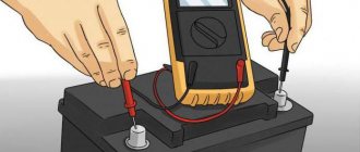
To perform such actions with a multimeter, you should switch it to the DC voltage measurement mode, setting the range slightly higher than the highest voltage reading on the battery. After this, connect the multimeter probe. Painted black, to the negative pole of the battery, and red, respectively, to the positive pole. The following readings appear on the display of the device:
If the battery is fully charged, then its voltage should not be lower than 12.6 V. Otherwise, the battery charge level does not exceed fifty percent and requires urgent recharging. An indicator not exceeding 11.6 V indicates that the battery is completely discharged. In order for the battery to charge for a long time, it is necessary to identify the causes of current loss, which happens in any car. This is facilitated by the alarm system, radio, dashboard and central locking device. If the total current loss does not exceed 80 mA, then the battery will operate without problems for several years. To operate, the multimeter is set to current measurement mode at 10 or 20 amperes:
Read also: Size of cutting discs for metal
Having removed the “negative” terminal, we connect one of the wires of the device. The second we touch the removed wiring. Polarity does not matter in this case:
How to measure DC voltage with a multimeter
Let's take a battery like this. As we can see, it says a current of 550 mAh, which it can supply to the load for an hour, that is, milliamps per hour, as well as the voltage that our battery has - 1.2 Volts. Voltage is understandable, but what is “current for an hour”? Let's say our load, a light bulb, consumes a current of 550 mA. This means the light bulb will shine for one hour. Or let's take a light bulb that shines weaker, and let it consume 55 mA, which means it can work for 10 hours.
We divide the 550 mA value that is written on the battery by the value that is written on the load and get the time during which all this will work until the battery runs out. In short, anyone who is good at mathematics will not have any difficulty understanding this miracle.