Theoretical information
Among various gases, air has the greatest technical application as a dielectric, since it is a natural insulation in most electrical structures: transformers, capacitors, air circuit breakers, power lines.
As a dielectric, air has positive properties: it quickly restores its electrical strength after breakdown, slightly changes its dielectric constant, and its dielectric losses are very small (tgδ = 10). Negative properties of air as a dielectric: Low thermal conductivity 0.00025-0.00036 W/cm*C, low electrical strength compared to solid and liquid dielectrics, the ability to moisturize, form oxides, and support combustion. The electrical strength of air is not constant and depends on a number of factors: Pressure, humidity, field shape between the electrodes, temperature, chemical composition of the gas.
The most important are:
1) the shape of the electrodes and the scheme for connecting them to the circuit, which determines the nature of the field in the gap between the electrodes;
2) air density and humidity;
3) the type of applied voltage (constant, alternating industrial frequency, high frequency and pulsed).
Mechanism of gas breakdown in a uniform field.
Gases at small values of electric field strength have extremely low conductivity, since the number of electric charge carriers is in the atmospheric air and therefore, when a small potential difference is applied to the air gap, a current will flow in it, almost imperceptible and not affecting the insulating ability of the air.
A small number of positive and negative ions and electrons contained in the gas, which, like neutral gas molecules, are in random thermal motion, when exposed to a field, receive some additional speed and begin to move, depending on the sign of the charge, in the direction of the field or against it. In this case, the charged particle receives energy.
W=q*Uλ
A magnetic field
Where q is the charge, Uλ is the potential difference at the mean free path.
If the field is sufficient, then we can assume that
Uλ=E*l,
Where E is the field strength, l is the average distance traveled by a charged particle without collision, that is, the mean free path is λ.
From here
Determining the degree of contamination
1.9.28. In areas that do not fall within the zone of influence of industrial sources of pollution (forests, tundra, forest-tundra, meadows), insulation with a smaller specific effective leakage path length than normalized in table can be used. 1.9.1 for 1st SZ.
1.9.29. Areas with the 1st SZ include territories that do not fall within the zone of influence of sources of industrial and natural pollution (swamps, high mountain areas, areas with slightly saline soils, agricultural areas).
1.9.30. In industrial areas, if supporting data are available, insulation with a greater specific effective creepage distance than normalized in table can be used. 1.9.1 for the 4th SZ.
1.9.31. The degree of pollution near industrial enterprises should be determined according to table. 1.9.3 - 1.9.12 depending on the type and estimated volume of products and the distance to the source of pollution.
The estimated volume of products produced by an industrial enterprise is determined by the summation of all types of products. The sanitary protection zone in the entrainment zone of an existing or under construction enterprise should be determined by the largest annual volume of production, taking into account the long-term development plan of the enterprise (no more than 10 years in advance).
1.9.32. The degree of pollution near thermal power plants and industrial boiler houses should be determined according to table. 1.9.13 depending on the type of fuel, power of the station and height of the chimneys.
1.9.33. When counting distances according to the table. 1.9.3 - 1.9.13 the boundary of the pollution source is a curve that encircles all places of emissions into the atmosphere at a given enterprise (thermal power plant).
1.9.34. If the volume of output and capacity of the thermal power plant exceeds those indicated in the table. 1.9.3 - 1.9.13, the SZ should be increased by at least one step.
1.9.35. The volume of products produced in the presence of several sources of pollution (shops) at one enterprise should be determined by summing the volumes of products of individual shops. If the source of pollutant emissions from individual production facilities (shops) is more than 1000 m from other sources of emissions from the enterprise, the annual volume of production must be determined for these production facilities and the rest of the enterprise separately. In this case, the calculated SZ must be determined in accordance with 1.9.43.
1.9.36. If one industrial enterprise produces products from several branches (or sub-sectors) of industry indicated in Table. 1.9.3 - 1.9.12, then SZ should be determined in accordance with 1.9.43.
1.9.37. The boundaries of the zone with a given NW should be adjusted taking into account the wind rose according to the formula
- where S is the distance from the border of the pollution source to the border of the area with a given northwest, adjusted taking into account the wind rose, m;
- S0 - normalized distance from the border of the pollution source to the border of the region with a given northwestern corner with a circular wind rose, m;
- W is the average annual frequency of winds at the point in question, %;
- W0 — frequency of winds of the same direction with a circular wind rose, %.
S/S0 values should be limited to 0.5 ≤ S/S0≤ 2.
1.9.38. The degree of pollution near dumps of dust-producing materials, warehouse buildings and structures, sewerage treatment facilities should be determined according to Table. 1.9.14.
1.9.39. The degree of pollution near roads with intensive use of chemical de-icing agents in winter should be determined according to table. 1.9.15.
1.9.40. The degree of pollution in the coastal zone of seas, salt lakes and reservoirs should be determined according to Table. 1.9.16 depending on the salinity of the water and the distance to the coastline. The estimated water salinity is determined from hydrological maps as the maximum salinity value of the surface layer of water in a zone up to 10 km deep into the water area. The degree of pollution above the surface of saline water bodies should be taken one step higher than in the table. 1.9.16 for a zone up to 0.1 km.
1.9.41. In areas exposed to winds with a speed of more than 30 m/s from the sea (frequency at least once every 10 years), the distances from the coastline given in Table. 1.9.16, should be increased by 3 times.
For reservoirs with an area of 1000-10000 m2, the SZ can be reduced by one step compared to the data in Table. 1.9.16.
1.9.42. The degree of contamination near cooling towers or spray ponds should be determined from Table. 1.9.17 with a specific conductivity of circulating water less than 1000 µS/cm and according to table. 1.9.18 with specific conductivity from 1000 to 3000 µS/cm.
1.9.43. The estimated SZ in the zone of overlapping pollution from two independent sources, determined taking into account the wind rose according to 1.9.37, should be determined from Table. 1.9.19 regardless of the type of industrial or natural pollution.
Table 1.9.3 NW near chemical plants and industries
| Estimated volume of output, thousand tons/year | NW at distance from the source of pollution, m | |||||||
| up to 500 | from 500 to 1000 | from 1000 to 1500 | from 1500 to 2000 | from 2000 to 2500 | from 2500 to 3000 | from 3000 to 5000 | from 5000 | |
| To 10 | 1 | 1 | 1 | 1 | 1 | 1 | 1 | 1 |
| From 10 to 500 | 2 | 1 | 1 | 1 | 1 | 1 | 1 | 1 |
| From 500 to 1500 | 3 | 2 | 1 | 1 | 1 | 1 | 1 | 1 |
| From 1500 to 2500 | 3 | 3 | 2 | 1 | 1 | 1 | 1 | 1 |
| From 2500 to 3500 | 4 | 3 | 3 | 2 | 2 | 1 | 1 | 1 |
| From 3500 to 5000 | 4 | 4 | 3 | 3 | 3 | 2 | 2 | 1 |
Table 1.9.4 NW near oil refining and petrochemical enterprises and production
| Sub-sector | Estimated volume of output, thousand tons/year | NW at distance from the source of pollution, m | |||||
| up to 500 | from 500 to 1000 | from 1000 to 1500 | from 1500 to 2000 | from 2000 to 3500 | from 3500 | ||
| Oil refineries | Up to 1000 | 1 | 1 | 1 | 1 | 1 | 1 |
| From 1000 to 5000 | 2 | 1 | 1 | 1 | 1 | 1 | |
| From 5000 to 9000 | 3 | 2 | 1 | 1 | 1 | 1 | |
| From 9000 to 18000 | 3 | 3 | 2 | 1 | 1 | 1 | |
| Petrochemical plants and plants | Up to 5000 | 3 | 2 | 1 | 1 | 1 | 1 |
| From 5000 to 10000 | 3 | 3 | 2 | 1 | 1 | 1 | |
| From 10000 to 15000 | 4 | 3 | 3 | 2 | 1 | 1 | |
| From 15000 to 20000 | 4 | 4 | 3 | 3 | 2 | 1 | |
| Synthetic rubber factories | Up to 50 | 1 | 1 | 1 | 1 | 1 | 1 |
| From 50 to 150 | 2 | 1 | 1 | 1 | 1 | 1 | |
| From 150 to 500 | 3 | 2 | 1 | 1 | 1 | 1 | |
| From 500 to 1000 | 3 | 3 | 2 | 1 | 1 | 1 | |
| Factories of rubber products | Up to 100 | 1 | 1 | 1 | 1 | 1 | 1 |
| From 100 to 300 | 2 | 1 | 1 | 1 | 1 | 1 | |
Table 1.9.5 NW near gas production and oil gas processing enterprises
| Sub-sector | Estimated volume of output | NW at distance from the source of pollution, m | ||
| up to 500 | from 500 to 1000 | from 1000 | ||
| Gas production | Regardless of volume | 2 | 1 | 1 |
| Petroleum gas processing | Regardless of volume | 3 | 2 | 1 |
Table 1.9.6 NW near pulp and paper production plants
| Sub-sector | Estimated volume of output, thousand tons/year | NW at distance from the source of pollution, m | |||
| up to 500 | from 500 to 1000 | from 1000 to 1500 | from 1500 | ||
| Production of cellulose and semi-cellulose | Up to 75 | 1 | 1 | 1 | 1 |
| From 75 to 150 | 2 | 1 | 1 | 1 | |
| From 150 to 500 | 3 | 2 | 1 | 1 | |
| From 500 to 1000 | 4 | 3 | 2 | 1 | |
| Paper production | Regardless of volume | 1 | 1 | 1 | 1 |
Table 1.9.7 NW near ferrous metallurgy enterprises and production facilities
| Sub-sector | Estimated volume of output, thousand tons/year | NW at distance from the source of pollution, m | |||||
| up to 500 | from 500 to 1000 | from 1000 to 1500 | from 1500 to 2000 | from 2000 to 2500 | from 2500 | ||
| Iron and steel smelting | Up to 1500 | 2 | 1 | 1 | 1 | 1 | 1 |
| From 1500 to 7500 | 2 | 2 | 2 | 1 | 1 | 1 | |
| From 7500 to 12000 | 3 | 2 | 2 | 2 | 1 | 1 | |
| Mining and processing plants | Until 2000 | 1 | 1 | 1 | 1 | 1 | 1 |
| From 2000 to 5500 | 2 | 1 | 1 | 1 | 1 | 1 | |
| From 5500 to 10000 | 3 | 2 | 1 | 1 | 1 | 1 | |
| From 10000 to 13000 | 3 | 3 | 2 | 1 | 1 | 1 | |
| Coke production | Up to 5000 | 2 | 2 | 2 | 2 | 2 | 1 |
| From 5000 to 12000 | 3 | 2 | 2 | 2 | 2 | 1 | |
| Ferroalloys | Up to 500 | 1 | 1 | 1 | 1 | 1 | 1 |
| From 500 to 700 | 2 | 2 | 1 | 1 | 1 | 1 | |
| From 700 to 1000 | 3 | 3 | 2 | 1 | 1 | 1 | |
| Production of magnesium products | Regardless of volume | 3 | 2 | 2 | 2 | 1 | 1 |
| Rolling and processing of cast iron and steel | Regardless of volume | 2 | 1 | 1 | 1 | 1 | 1 |
Table 1.9.8 NW near enterprises and production of non-ferrous metallurgy
| Sub-sector | Estimated volume of output, thousand tons/year | NW at distance from the source of pollution, m | ||||||
| up to 500 | from 500 to 1000 | from 1000 to 1500 | from 1500 to 2000 | from 2000 to 2500 | from 2500 to 3500 | from 3500 | ||
| Aluminum production | Up to 100 | 1 | 1 | 1 | 1 | 1 | 1 | 1 |
| From 100 to 500 | 2 | 2 | 1 | 1 | 1 | 1 | 1 | |
| From 500 to 1000 | 3 | 3 | 2 | 2 | 1 | 1 | 1 | |
| From 1000 to 2000 | 3 | 3 | 3 | 2 | 2 | 1 | 1 | |
| Nickel production | From 1 to 5 | 1 | 1 | 1 | 1 | 1 | 1 | 1 |
| From 5 to 25 | 2 | 2 | 1 | 1 | 1 | 1 | 1 | |
| From 25 to 1000 | 3 | 2 | 2 | 1 | 1 | 1 | 1 | |
| Production of rare metals | Regardless of volume | 4 | 4 | 3 | 3 | 2 | 2 | 1 |
| Zinc production | Regardless of volume | 3 | 2 | 1 | 1 | 1 | 1 | 1 |
| Production and processing of non-ferrous metals | Regardless of volume | 2 | 1 | 1 | 1 | 1 | 1 | 1 |
Table 1.9.9 NW near enterprises producing construction materials
| Sub-sector | Estimated volume of output, thousand tons/year | NW at distance from the source of pollution, m | ||||||
| up to 250 | from 250 to 500 | from 500 to 1000 | from 1000 to 1500 | from 1500 to 2000 | from 2000 to 3000 | from 3000 | ||
| Cement production | Up to 100 | 1 | 1 | 1 | 1 | 1 | 1 | 1 |
| From 100 to 500 | 2 | 2 | 1 | 1 | 1 | 1 | 1 | |
| From 500 to 1500 | 3 | 3 | 2 | 1 | 1 | 1 | 1 | |
| From 1500 to 2500 | 3 | 3 | 3 | 2 | 1 | 1 | 1 | |
| From 2500 to 3500 | 4 | 4 | 3 | 3 | 2 | 1 | 1 | |
| From 3500 | 4 | 4 | 4 | 3 | 3 | 2 | 1 | |
| Asbestos production, etc. | Regardless of volume | 3 | 2 | 1 | 1 | 1 | 1 | 1 |
| Production of concrete products, etc. | Regardless of volume | 2 | 1 | 1 | 1 | 1 | 1 | 1 |
Table 1.9.10 NW near machine-building enterprises and production facilities
| Estimated volume of output | NW at distance from the source of pollution, m | |
| up to 500 | from 500 | |
| Regardless of volume | 2 | 1 |
Table 1.9.11 NW near light industry enterprises
| Sub-sector | Estimated volume of output | NW at distance from the source of pollution, m | ||
| up to 250 | from 250 to 500 | from 500 | ||
| Fabric processing | Regardless of volume | 3 | 2 | 1 |
| Production of artificial leather and film materials | Regardless of volume | 2 | 1 | 1 |
Table 1.9.12 NW near enterprises for the extraction of ores and non-metallic minerals
| Sub-sector | Estimated volume of output | NW at distance from the source of pollution, m | ||
| up to 250 | from 250 to 500 | from 500 | ||
| Iron ore, etc. | Regardless of volume | 2 | 1 | 1 |
| Coal* | Regardless of volume | 3 | 2 | 1 |
* Applies to the determination of sanitary protection near waste heaps.
Table 1.9.13 NW near thermal power plants and industrial boiler houses
| Type of fuel | Power, MW | Chimney height, m | NW at distance from the source of pollution, m | |||||
| up to 250 | from 250 to 500 | from 500 to 1000 | from 1000 to 1500 | from 1500 to 3000 | from 3000 | |||
| Thermal power plants and boiler houses using coal with ash content less than 30%, fuel oil, gas | Regardless of power | Any | 1 | 1 | 1 | 1 | 1 | 1 |
| Thermal power plants and boiler houses using coal with an ash content of more than 30%. | Up to 1000 | Any | 1 | 1 | 1 | 1 | 1 | 1 |
| From 1000 to 4000 | Up to 180 | 2 | 2 | 2 | 1 | 1 | 1 | |
| From 180 | 2 | 2 | 1 | 1 | 1 | 1 | ||
| Thermal power plants and boiler houses on shale | Up to 500 | Any | 3 | 2 | 2 | 2 | 1 | 1 |
| From 500 to 2000 | Up to 180 | 4 | 3 | 2 | 2 | 2 | 1 | |
| From 180 | 3 | 3 | 2 | 2 | 2 | 1 | ||
Table 1.9.14 NW near dumps of dusty materials, warehouse buildings and structures, sewage treatment facilities (ash dumps, salt dumps, slag dumps, large industrial landfills, waste incineration plants, warehouses and elevators of dusty materials, warehouses for storing mineral fertilizers and pesticides, hydraulic mines and processing plants, aeration stations and other sewage treatment facilities)
| NW at distance from the source of pollution, m | ||
| up to 200 | from 200 to 600 | from 600 |
| 3 | 2 | 1 |
Table 1.9.15 NW near roads with intensive use of chemical deicing agents in winter
| NW at distance from roads, m | ||
| up to 25 | from 25 to 100 | from 100 |
| 3 | 2 | 1 |
Table 1.9.16 NW in the coastal zone of seas and lakes with an area of more than 10,000 m2
| Type of reservoir | Estimated water salinity, g/l | Distance from coastline, km | NW |
| Unsalted | Up to 2 | Up to 0.1 | 1 |
| Lightly salted | From 2 to 10 | Up to 0.1 | 2 |
| From 0.1 to 1.0 | 1 | ||
| Moderately saline | From 10 to 20 | Up to 0.1 | 3 |
| From 0.1 to 1.0 | 2 | ||
| From 1.0 to 5.0 | 1 | ||
| Highly salted | From 20 to 40 | Up to 1.0 | 3 |
| From 1.0 to 5.0 | 2 | ||
| From 5.0 to 10.0 | 1 |
Table 1.9.17 NW near cooling towers and spray ponds with specific conductivity of circulating water less than 1000 µS/cm
| NW district | Distance from cooling towers (spray pool), m | |
| up to 150 | from 150 | |
| 1 | 2 | 1 |
| 2 | 3 | 2 |
| 3 | 4 | 3 |
| 4 | 4 | 4 |
Table 1.9.18 NW near cooling towers and spray ponds with specific conductivity of circulating water from 1000 to 3000 µS/cm
| NW district | Distance from cooling towers (spray pool), m | ||
| up to 150 | from 150 to 600 | from 600 | |
| 1 | 3 | 2 | 1 |
| 2 | 4 | 3 | 2 |
| 3 | 4 | 4 | 3 |
| 4 | 4 | 4 | 4 |
Table 1.9.19 Estimated SZ with superposition of pollution from two independent sources
| NW from first source | Estimated SZ for the degree of pollution from the second source | ||
| 2 | 3 | 4 | |
| 2 | 2 | 3 | 4 |
| 3 | 3 | 4 | 4 |
| 4 | 4 | 4 | 4 |
Electrical porcelain
It is the most common ceramic electrical insulating material. The composition of porcelain includes: kaolin - white clay, fire clay, quartz and feldspar. The production of porcelain products consists of the following operations: grinding the components of porcelain and mixing them with water into a homogeneous mass. By pressing, grinding, casting into plaster molds or extruding from this mass, products of the desired configuration are obtained. To remove excess water, the products are dried, then they are covered with a glassy mass - glaze, which reduces the hygroscopicity of porcelain, gives a certain color to the products and creates an even, smooth surface during firing. After glazing, the product is dried again and fired in ovens at a temperature of 1320 - 1450 ° C. Porcelain is characterized by high heat resistance, resistance to electric arcs and very low water absorption. Linear (suspension and pin) insulators, stationary (support and bushing) insulators, hardware insulators, installation porcelain products (rollers, parts of fuses, cartridges, plugs, etc.) are made from porcelain. Electric strength of porcelain 6 – 10 kV/mm; ε = 5 – 6.5. In addition to porcelain, another ceramic material is used - steatite, made on the basis of the mineral - talc. Soapite, compared to porcelain, has higher electrical insulating and physical-mechanical properties.
conclusions
Insulation resistance monitoring
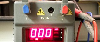
Modern instruments make it possible to evaluate the insulation quality of various equipment and cables with high accuracy and under various conditions. The costs of testing by specialized service organizations or departmental services are offset by reductions in costs for downtime and repair of electrical equipment, as well as compensation to consumers in the event of emergency power outages.
If you need professional advice on checking the insulation of cables and electrical equipment, just send us a message!
Vacuum as an insulator.
When metal electrodes are placed in a gas with a pressure of less than 10-2 Pa, there are not enough gas molecules to generate a noticeable current in the interelectrode gap, and in this case they speak of high vacuum insulation. Ionization of residual gas molecules upon collision with electrons or positively charged ions emitted from the electrodes rarely occurs at such pressures. Under high vacuum conditions at a constant voltage below 20 kV, breakdown may not occur on the cathode surface at a field strength of up to 5 MV/cm, and at the anode at a field strength several times higher. However, at higher voltages, the cathodic gradient at which breakdown occurs rapidly decreases. Breakdown between metal electrodes in a vacuum occurs due to the exchange of charged particles between the cathode and anode. An electron emitted from the cathode is accelerated by the electric field and strikes the anode, knocking out positive ions and photons. Positive ions and some photons fall on the cathode; The ions are accelerated by the electric field and cause the emission of secondary electrons. At a certain critical value of voltage and electric field gradient for a given electrode material, this process becomes unstable and spark breakdown occurs.
High-vacuum insulation is particularly widely used in electronics, both for accelerating low-energy electrons in conventional vacuum devices and for high-voltage applications in X-ray instruments and nuclear research accelerators.
Instruments for insulation quality control
The choice of instruments for monitoring the quality of insulation depends on the type of electrical equipment being examined, cables, test method and conditions. When choosing meters, you should pay attention to the following factors:
- permissible measuring range of the control and measuring device, electrical safety category (CAT I...IV);
- parameters of the electrical system under study (DC/AC voltage at the input/output, load current, frequency, power), the possibility of turning off the power supply to the equipment during research;
- properties of the insulation material (thermal, dielectric);
- environmental parameters (humidity level, temperature);
- Possibility of access to the equipment under test (contact, remotely).
Universal meters of electrical parameters - multimeters, megohmmeters. For household, office and industrial low-voltage electrical installations and wires, CAT I, II meters are sufficient; for high-voltage power lines or distribution cells - at least CAT III (1000 V).
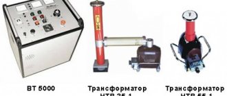
To test the insulation of cables and electrical equipment with direct/alternating high voltage, T99/1, T26/1, MMG5/10, HPG 50/70 units with devices for converting defects (burning) are used. For remote detection of defects in underground cable conductors and estimation of the distance to a fault, shock pulse generators RSP 3, PWG 2000 and reflectometers STELL REIS-205, STELL REIS-305, STELL REIS-405 are popular.
STELL-RAYS 405 reflectometer for checking cables
The indisputable advantages of thermal imagers of the Testo 868/871/872/882/885 line are compactness, mobility, and ease of use. Fluke TiX500/580 thermal imagers have an accuracy of 0.025 °C and an extended measurement range of up to +400 °C.
What is electrical strength?
Electrical strength for any insulation should be understood as the minimum potential difference applied per unit thickness at which discharges begin to occur. Electric strength is a nonlinear function, the change of which depends on the following factors:
The work of the electric field when moving a charge. operating principle
- Insulation thickness;
- Dielectric constant;
- Temperatures of both the surrounding space and the insulation itself;
- Type of dielectric;
- Type of applied voltage (AC or DC).
Thus, we can say that the insulation strength determines the breakdown voltage. In practice, for each material this parameter is calculated empirically after numerous tests.
Rice. 1. Effect of voltage on a dielectric
The value is measured as V/mm or kV/cm, etc., for example, dry air, on average, has a strength of 32 kV/cm.
However, the strength of the insulation will also depend on the aggregate state of the material:
- Solid dielectrics - the most common in cable and wire products, are intended for the manufacture of insulation of cores, device housings, gaskets, etc. After a breakdown or micro-breakdown, the insulation is destroyed, channels are formed through which a repeated breakdown will occur at a lower voltage.
- Liquid dielectrics - the most common option is transformer oil, used in transformers, switches, and high voltage cables. Due to their movable structure, they have the ability to recover, which makes them excellent in oil circuit breakers, where the insulation simultaneously extinguishes the arc and is then restored.
- Gaseous insulation - air is used around the windings of a transformer or other electrical apparatus, the same can be said for some types of high-voltage circuit breakers. But modern devices often use SF6 gas or nitrogen. Gases are also easily restored after a breakdown.
Physically, the electrical strength of dielectrics is ensured due to the absence of free charge carriers in the material. Dielectric molecules hold electrons so firmly in their outer orbits that even applied voltage cannot remove them from their orbits. Of course, if we consider the ideal option - the arrangement of the material between two plates to which voltage is applied, then it will not flow through it. However, all atoms will receive additional energy, which will create a greater electric field strength, both in the entire solid insulation and in each individual atom.
But, if between the above plates you place not one piece of dielectric, but two from different materials, or half from air and the other from plastic, then the electric field strength in these materials will differ due to the fact that they have different dielectric constants. This is one of the most important factors in reducing electrical strength.
High voltage insulation tests make it possible to identify local defects that cannot be detected by other methods; In addition, this test method is a direct way to control the ability of the insulation to withstand the effects of overvoltages and provides some confidence in the quality of the insulation. A test voltage greater than the operating voltage is applied to the insulation, and normal insulation passes the test, while defective insulation breaks through.
When testing with increased voltage, three main types of test voltages are used: increased power frequency voltage, rectified direct voltage and impulse test voltage (standard lightning impulses).
The main type of test voltage is power frequency voltage. Application time
such voltage is 1 minute, and
the insulation is considered to have passed the test
if during this time no breakdown or partial damage to the insulation was observed. In some cases, tests are carried out at higher frequency voltages (usually 100 or 250 Hz).
With a large capacity of the insulation being tested (when testing cables, capacitors), the use of high-power testing equipment is required, therefore such objects are most often tested with increased direct voltage. As a rule, at a constant voltage, dielectric losses in the insulation, leading to its heating, are several orders of magnitude lower than at an alternating voltage of the same effective value; in addition, the intensity of partial discharges is much lower. In such tests, the load on the insulation is significantly less than in AC tests, so a higher DC voltage than the AC test voltage is required to break down the defective insulation.
When testing with constant voltage, the leakage current through the insulation is additionally monitored. The time for applying a constant test voltage is from 5 to 15 minutes. The insulation is considered to have passed the test if it has not broken through and the leakage current value has not changed or decreased by the end of the test.
The third type of test voltage is standard lightning voltage pulses with a rise time of 1.2 μs and a half-time duration of 50 μs. Impulse voltage tests are carried out because the insulation during operation is exposed to lightning overvoltages with similar characteristics. The effect of lightning impulses on insulation differs from that of 50 Hz voltage due to the much greater rate of voltage change, resulting in a different voltage distribution across complex insulation such as transformer insulation; in addition, the breakdown process itself at short times differs from the breakdown process at a frequency of 50 Hz, which is described by volt-second characteristics. For these reasons, testing with power frequency voltage is in some cases not enough.
The impact of lightning overvoltages on insulation is often accompanied by the operation of protective arresters that cut off the overvoltage wave a few microseconds after its onset; therefore, during testing, pulses cut off 2–3 μs after the start of the pulse (cut off standard lightning pulses) are used. The pulse amplitude is selected based on the capabilities of the equipment that protects the insulation from overvoltages, with some reserves and based on the possibility of accumulation of hidden defects during repeated exposure to pulse voltages. Specific values of test pulses are determined according to GOST 1516.1-76.
Internal insulation tests are carried out using the three-impact method. Three pulses of positive and negative polarity are applied to the object, first full and then cut. The time interval between pulses is at least 1 minute. The insulation is considered to have passed the test if no breakdowns occurred during the test and no damage was detected. The damage detection technique is quite complex and is usually carried out using oscillographic methods.
External insulation of equipment is tested by the shock method, when fifteen pulses of both polarities, both full and cut, are applied to the object at intervals of at least one minute. The insulation is considered to have passed the test if in each series of fifteen pulses there were no more than two full discharges (overlaps).
All types of tests can be divided into three main groups, differing in purpose and, accordingly, in volume and standards:
· testing new products at the manufacturing plant;
· tests after laying or installing new equipment, tests after major repairs;
· periodic preventive tests.
During preventive or post-repair tests, the ability of the insulation to work without failure until the next regular tests is checked. Insulation testing with increased voltage provides only an indirect assessment of the long-term electrical strength of the insulation, and its main task is to check the absence of gross concentrated defects.
Test voltages for new equipment at manufacturing plants are determined by GOST 1516.2-97, and during preventive tests, test voltage values are accepted to be 10–15% lower than factory standards. This reduction takes into account the aging of the insulation and reduces the risk of accumulation of defects that arise during testing.
High voltage insulation monitoring under operating conditions is carried out for some types of equipment (rotating machines, power cables) with a rated voltage not higher than 35 kV
, since at higher voltages the test setups are too bulky.
Cables.
Test voltages for cables are set in accordance with the expected level of internal and lightning overvoltages.
At manufacturing plants, oil-filled cables and cables with low-viscosity impregnation are tested at increased industrial frequency voltage (about 2.5 Un). To prevent damage to the insulation, cables with viscous impregnation and gas cables are tested with a rectified voltage of the order of (3.5..4) Unom, where Unom is the linear voltage at operating voltages of 35 kV or less.
In addition, the insulation resistance is measured, and at operating voltages of 6 kV or more, the insulation resistance and tgδ
.
After laying the cable, after major repairs and during preventive tests, the cable insulation is tested with increased rectified voltage. The test time for cables with a voltage of 3–35 kV is 10 minutes for cables after installation and 5 minutes after major repairs and during maintenance tests. The frequency of preventive tests ranges from twice a year to once every three years for different cables. During the tests, the leakage current is monitored, the values of which range from 150 to 800 μA/km for normal insulation. The insulation resistance is measured before and after the tests.
Power transformers
. At the manufacturing plant, internal and external insulation is tested with full and chopped standard lightning impulses, as well as with increased alternating power frequency voltage. Detection of damage to longitudinal insulation is most often carried out by oscillography of the current in the neutral of the transformer and comparison of the oscillogram with a standard one.
If the insulation of the neutral and line terminal is the same, then when testing with increased alternating voltage, both ends of the winding under test are insulated and voltage is applied to the winding from an external source. If the neutral insulation level is reduced, then tests are carried out with an induced voltage of high frequency (up to 400 Hz) so that a voltage of about 2 Unom can be applied. The neutral is grounded or an extraneous voltage of the same frequency is applied to it. Since the self-induction EMF in the winding is proportional to the frequency, then at the same maximum induction it is possible to apply an increased test voltage compared to the operating voltage.
When testing insulation, each electrically independent circuit or parallel branch must be tested in turn (in the latter case, if there is complete insulation between the branches), and the test voltage is applied between the terminal and the grounded frame, all other windings are grounded. Insulation resistance measurements are carried out before and after high voltage tests.
Before turning on the newly installed transformer for the first time, measure the breakdown voltage of the transformer oil, insulation resistance and absorption coefficient, ratio C
2/
C
50,
tgδ
(the value of which is compared with the results of factory tests).
During periodic preventive tests, the same tests are carried out as before the first start-up, but the permissible values of tgδ
at the same time increased. Insulation tests with increased voltage during preventive tests are assumed for windings with voltages up to 35 kV, the values of the test voltages are reduced to 0.85-0.9 of the factory test voltage.
The frequency of preventive tests for different transformers ranges from once a year to once every four years.
High voltage bushings
. The main type of control is periodic inspection (from once every three days to once every six months); the insulation resistance between the special measuring plate of the input and the connecting sleeve is also measured. The frequency of such tests varies for different bushings, but at least once every 4 years.
5.1. Standardized values [1]
Tests of electrical equipment with increased voltage are carried out before acceptance into operation within the time limits provided for by the schedule of scheduled maintenance and preventive tests of electrical equipment.
The standards, test conditions and procedure for conducting them are presented in Table 1.
Table 1. Standards, test conditions for high voltage and instructions for their implementation
| Test object | Test standards | Directions |
| 1 | 2 | 3 |
| 1. Insulation of the windings and current-carrying parts of the cable of a hand-held power tool relative to the housing and external metal parts | For power tools with voltage up to 50 V, the test voltage is 550 V, for power tools with voltage above 50 V, power up to 1 kW - 900 V, power over 1 kW - 1350 V. Test time - 1 min. | The body of the power tool and the parts connected to it, made of dielectric material, must be wrapped in metal foil and connected to a grounding conductor. If the insulation resistance is at least 10 MΩ, then the high voltage insulation test can be replaced by a one-minute insulation resistance measurement with a mega-ohmmeter, voltage 2500 V |
| 2. Insulation of the windings of step-down transformers | At a rated voltage of the primary winding of the transformer 127 - 220V, the test voltage is 1350 V, at a rated voltage of the primary winding 380 - 440 V, the test voltage is 1800 V. Test duration - 1 min. | The test voltage is applied alternately to each of the windings. In this case, the remaining windings must be connected to a grounded case and magnetic core |
| 3. Insulation of switchgears, elements of drives of switches, short circuits, separators, devices, as well as secondary circuits of control, protection, automation, telemechanics, measurements with all connecting devices, voltage above 60V, not containing devices with microelectronic elements | Test voltage 1000 V. Test duration – 1 min. | Instead of testing with industrial frequency voltage, it is allowed to take a one-minute measurement of insulation resistance with a megohmmeter, voltage 2500 V, except for relay protection and automation circuits |
| 4. Insulation of power and lighting electrical wiring | Test voltage 1000 V. Test duration – 1 min. | Performed if the measured insulation resistance is less than 1 MOhm |
| 5. Cables with voltage up to 10 kV | Test voltage depending on the rated operating voltage, kV, for cables: – with paper insulation 2 – 12 (10 – 17); 3 – 18 (15 – 25); 6 – 36 (36); 10 – 60 (60). – with rubber insulation 3 – 6 (6) 6 – 12 (12) 10 – 20 (20) Without brackets, the indicated values of test voltages during acceptance tests, in brackets - during operational tests. The duration of application of the test voltage during acceptance tests is 10 minutes, during operational tests - 5 minutes. For cables with rubber insulation, the duration of application of the test voltage for all types of tests is 5 minutes. |
5.2. Instruments and installations for testing electrical equipment with high voltage [2 – 5]
To test electrical equipment with increased voltage, the following devices and installations can be used:
· universal breakdown installation UPU-5M;
· apparatus for testing the insulation of power cables and solid dielectrics AID 70/50;
· small-sized testing unit MIU-60;
· installation for testing cable insulation UI-70;
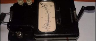
· megohmmeters of type F4100, F4101, F4102 and ESO202/2 (G) with an output voltage of 2500 V.
The description and diagrams for connecting megaohmmeters to the equipment being tested are given in laboratory work No. 3.
5.2.1. Universal punching device UPU-5M
Designed to measure the electrical strength of insulation when testing with direct or alternating voltage up to 6 kV.
The installation (Fig. 1) is available in two versions:
· “U” – universal (AC and DC voltage);
· “P” – only alternating voltage;
Rice. 1. Universal breakdown device UPU-5M
The main technical characteristics of UPU-5M are given in Table 2.
Table 2. Technical characteristics of the universal breakdown device UPU-5M
| Parameter | Magnitude |
| Output voltage setting range: | |
| – constant, kV (only for option “U”) | 0,2 – 6 |
| – AC, kV | 0,2 — 6 |
| Leakage current measurement, mA | 0,1 — 100 |
| Threshold setting range | |
| – voltage, kV | 0,2 – 6 |
| – leakage current, mA | 1 — 99 |
| Maximum output power, not less, kVA | 0,6 |
5.2.2. Apparatus for testing the insulation of power cables and solid dielectrics AID 70/50
The testing device AID-70/50 (Figure 5.2) is designed for testing the insulation of power cables and solid dielectrics with rectified electrical voltage, as well as for testing solid dielectrics with a sinusoidal electrical voltage with a frequency of 50 Hz.
Rice. 2. Apparatus for testing the insulation of power cables and solid dielectrics AID-70/50
Table 3. Technical characteristics of AID-70/50
| Parameter | Magnitude |
| Single-phase AC supply voltage, V | 220+11 |
| Parameters of the device on rectified voltage in continuous mode at the rated voltage in the network | |
| – highest operating voltage, kV, | 70 |
| – maximum operating current, mA, | 12 |
| Parameters of the device on alternating voltage in continuous mode at the rated voltage in the network | |
| – highest operating voltage (rms value), kV | 50 |
| – maximum operating current (rms value), mA | 20 |
| Power consumption, kVA, no more | 3 |
5.3 Procedure for testing insulation with increased voltage
Measure the insulation resistance of the object being tested.
Assemble the test circuit in the following sequence:
· prepare the test installation for operation in accordance with the manufacturer’s instructions;
· apply portable grounding to the high-voltage terminal of the test installation;
· make the necessary shutdowns (disconnections) of the electrical equipment under test;
· apply portable grounding connections to the electrical equipment being tested or turn on the grounding blades;
· set the voltage regulator of the test installation to the position corresponding to the zero voltage value at the output;
· connect the high-voltage terminal to the object under test (bus, cable, wire, motor winding terminal, transformer, etc.);
· remove the portable grounding from the high-voltage terminal of the testing installation (from this moment on, making changes to the test circuit is strictly prohibited). Make all changes in the test circuit only with the high-voltage terminal disconnected and grounded;
· connect the test setup to the network.
Before removing the portable ground from the high-voltage terminal and connecting the test installation to the network, the work operator is obliged to loudly and clearly warn the team about the supply of voltage to the test object and make sure that his warning is heard by all members of the team.
After turning on the test setup, it is necessary to increase the output voltage from zero to the test value. The rate of voltage rise to 1/3 of the test value can be arbitrary. Thereafter, the rate of rise of the test voltage must be capable of being visually read by the measuring instruments, and once the specified voltage value is reached, it must be maintained constant for the required test time.
After the test time has expired, the voltage gradually decreases to zero, after which the test setup can be turned off. After this, it is necessary to re-measure the resistance of the tested insulation.
Testing insulation with increased voltage makes it possible to verify the presence of the necessary insulation strength margin and the absence of local defects that cannot be detected by other methods. Testing of insulation with increased voltage must be preceded by a thorough inspection and assessment of the condition of the insulation by other methods (measuring insulation resistance, determining the moisture content of the insulation, etc.).
The value of the test voltage for each type of equipment is determined by the established standards of the “Rules for the operation of consumer electrical installations”.
The insulation is considered to have passed the electrical test with increased voltage if there was no breakdown, overlap on the surface, surface discharges, an increase in the leakage current above the normalized value, or the presence of local heating from dielectric losses. If one of these factors is not met, the insulation fails the electrical test.
A typical scheme for testing the insulation of electrical equipment with increased alternating voltage is presented in Figure 3.
Rice. 3. Scheme for testing the insulation of electrical equipment with increased alternating voltage
The test installation consists of a regulating device TV1 (autotransformer), a step-up transformer TV2, a protection device QF (automatic circuit breaker), means for measuring current and voltage pV1, pV2, pA and additional resistance R, which is necessary to protect the installation in case of breakdown of the insulation of the test object.
Voltage measurement can be carried out either by an indirect method using special measuring transformers TV3, while the measuring transformer TV3 and voltmeter pV2 are connected to the secondary circuit of the step-up transformer (in Figure 5.5, the voltmeter V calibrated in kV is thus included), or by direct measurement of the test voltage directly on the test object using kilovoltmeters (the use of a TV3 measuring transformer is not required in this case).
The QF circuit breaker is designed to quickly disconnect the test setup when a large current occurs through the control transformer at the time of insulation breakdown. Thus, this circuit breaker limits the time the test voltage is exposed to the object during an insulation breakdown and protects the test installation from damage.
To test insulation with direct (rectified) voltage, test installations are used, which are schematically similar to installations for testing insulation with increased power frequency voltage, only a rectifier device is introduced into the circuit. An example test setup for DC testing is shown in Figure 4.
Rice. 4. Scheme for testing the insulation of electrical equipment with increased direct voltage
5.4. The procedure for testing using the AID-70 installation
5.4.1. Test preparation
Install the test voltage source (hereinafter referred to as the source) near the test object. Connect the object to the high voltage terminal of the source.
Ground the source with the flexible copper wire supplied with the device, the cross-section of which is 4 mm2.
Connect the source cables to the corresponding connectors on the control panel.
Remove the device control panel from the source at a distance of at least 3 m.
Connect the control panel to the power supply and ground it using the network cable supplied with the device.
WORK WITHOUT GROUNDING IS PROHIBITED!
5.4.2. Testing
Persons present during testing must be at least 3 m away from the source and the tested object.
Insert the special key for the device into the control panel switch and turn on the required type of test voltage, and the green signal should light up.
When working on rectified voltage, in order to avoid failure of the source, as well as to correctly measure the value of the test voltage, strictly monitor the position of the “kV” toggle switch.
Rotate the test voltage regulator knob counterclockwise and set it to its original position until it stops.
Turn on the test voltage with the button, and the red signal should light up.
By rotating the test voltage regulator knob clockwise and observing the kilovoltmeter readings, set the required test voltage value.
When testing capacitive objects, it must be remembered that after the voltage regulator knob stops rotating, the test voltage on the object continues to increase (the kilovoltmeter needle continues to deviate) as the capacity is charged.
In such cases, the voltage increase must be carried out slowly and smoothly, without exceeding the normalized value of the test voltage at the facility, and also without exceeding the highest operating voltage of the device, equal to 70 kV.
When working on a rectified test voltage, the load current of up to 1 mA should be measured with a microammeter, and the button that shunts this device should be pressed.
After completing the test, it is necessary to set the test voltage regulator knob, rotating it counterclockwise, to its original position until it stops.
Use the button to turn off the test voltage and only then disconnect the device from the network using a special key, setting it to position 0.
Control over the removal of residual capacitive charge from the test object must be carried out by observing the reading of the device’s kilovoltmeter - the kilovoltmeter needle should be at the numerical scale mark 0.
In the case of testing with a rectified voltage equal to 70 kV, a capacitive object with a capacitance value of more than 4 μF, after the end of the test and the voltage regulator knob is set to its original position all the way, the residual charge from the object must be removed using a special discharge rod with a limiting resistance, then turn off the test with a button voltage and only then disconnect the device from the network using a special key.
The use of a special discharge rod prevents failure of the secondary winding of the high-voltage transformer.
When testing capacitive objects with a rectified voltage below 70 kV, the value of the maximum permissible capacitance of the tested object, without the use of a special discharge rod, should be determined by the formula:
| C = 19600 / U2, | (5.1) |
where C
– maximum permissible capacity of the test object without the use of a special discharge rod, μF;
U
– test voltage, kV.
Glass
It is obtained by melting silica - SiO2 (in the form of sand) with oxides of various metals - sodium, potassium, lead, calcium (in the form of soda, saltpeter, borax, various rocks). Glass is an amorphous body, so it does not have a specific melting point. When heated, glass softens and becomes liquid. In this state, glass can be blown, drawn, pressed, or cast. The physical and mechanical properties of glass depend on its composition and processing. If ordinary glass is fragile, then especially tempered glass - stalinite - has high impact strength. Glass is practically waterproof; it is not affected by acids (except for hydrofluoric acid) and alkali. However, glasses containing only alkali oxides (Na2O, K2O) dissolve well in water (liquid glass). The electrical insulating properties of glass are very high. As glass heats up, it quickly loses its insulating properties. In electrical engineering, glass is used to make cylinders for lighting and electronic lamps, insulators, and the like. Glass can be used to produce fibers with a diameter of up to 0.005 - 0.006 mm. The individual fibers are spun into threads. Glass threads (glass yarn) are used for heat-resistant insulation of PSD grade conductors. Electric strength of glass 10 – 40 kV/mm; ε = 5.5 – 10.
Methods for quality control of insulation of wires and electrical equipment
An example of a protocol for checking the insulation resistance of cables and wires.
Let's consider the main methods for monitoring the quality of insulation of wires and electrical equipment. Parameters characterizing the quality of insulation:
- absorption coefficient (R60/R15 – ratio of resistances calculated 60 and 15 seconds after applying voltage);
- dielectric loss tangent (tg δ=P/Q – ratio of active and reactive power);
- electrical strength when applying increased voltage 3-35 kV;
- temperature of surface or internal layers of insulation.
Insulating tape
Insulating tape or duct tape is probably familiar to everyone. In appearance, it is a narrow (not always) roll of colored or black material. The inner side of the tape is coated with an adhesive composition for gluing. The tape is used by winding it onto the insulation site with overlapping turns.
Power cables: main types of electrical cables and features of wiring (100 photos)
According to the material of manufacture, insulating tape can be:
- Polyvinyl chloride (PVC)
- Cotton (CB)
The first type of electrical tape is available in a wide range of colors. CB electrical tape is black in color with a characteristic smell of rubber or bitumen.
PVC electrical tape
PVC electrical tape is made from vinyl by applying an adhesive composition to one side of the tape. The width of PVC insulating tape is from 15 to 50 mm. The advantages of PVC electrical tape are its high elasticity. Disadvantages in changing its properties with decreasing and increasing temperature. PVC electrical tape is excellent, but its use does not extend beyond low voltages.
HB electrical tape
CB electrical tape is characteristically black in rolls 15-50 mm wide. It is made from cotton tapes impregnated in rubber and applying an adhesive layer to one side. The combination of cotton (possibly fiberglass) makes the cotton tape resistant to temperature fluctuations and its use extends to networks with voltages over 1000 V.
In physics
When the voltage in the conductors increases, the strength values in the electric fields also increase accordingly. The insulation breakdown itself occurs in conductors, which can be cable cores or plates.
In this case, the strength of electricity is measured in kilovolts per millimeter or kilovolts per centimeter. This is suitable for flat cables made in the form of tapes or plates with uniform insulating layers. A great example is the paper capacitor.
Breakdowns in insulation cause short circuits in the electrical network. For insulation layers, its insulation strength values are a key parameter.
You can read about the exact strength of insulating layers on certain electrical installations or electrical equipment in the relevant sections of GOST.
Electrical strength of air gaps
Fundamentals > Electrical Materials > Dielectrics
Electrical strength of air gaps Under normal conditions (pressure 0.1 MPa; temperature 293 K, absolute humidity 11 g/m3), the discharge voltage of the air gap between flat electrodes (uniform field) s is the distance between the electrodes, m. Dependence of discharge voltages on the distance between electrodes for gaps with a sharply inhomogeneous field (rod - rod, rod - plane) at voltages with a frequency of 50 Hz and pulsed (50%) are shown in Fig. 6-1 and 6-2. Under conditions other than normal, where is the relative density of air; p—pressure, Pa; T—temperature, K; k is a correction factor for taking into account air humidity (Fig. 6-3). For gaps with a weakly inhomogeneous field (balls), the coefficient k is taken equal to unity. At voltages whose amplitudes are less than 141 kV, the percentage correction for humidity decreases compared to that indicated in Fig. 6-3, proportional to the voltage amplitude. For pre-discharge times less than 10 μs, the percentage correction for humidity decreases in proportion to the value of the pre-discharge time, i.e., relative to 10 μs.
Rice. 6-1. Discharge voltages for rod-to-rod and rod-to-plane air gaps at 50 Hz.
Rice. 6-2. Discharge 50% impulse voltages for air gaps rod-rod and rod-plane.
Rice. 6-3. Correction factor k to take into account air humidity (according to GOST 1516-731)
The conditions for the occurrence of a corona discharge in the case of a sharply repeated field are described in the section. When choosing insulating distances through the air in structures with sharply non-uniform fields, you should use the discharge characteristics of gaps with rod electrodes according to Fig. 6-1 and 6-2 (as the most unfavorable case). For high-voltage devices, the minimum insulation distances through the air can be taken equal to: where Un in kVrms. If it is necessary to increase the electrical strength of air gaps in order to reduce distances when there is not enough space, measures are taken to level the electric field to a slightly non-uniform one, for which: a) increase the radii of curvature of the electrodes so that they exceed the interelectrode distance; b) provide for careful processing and elimination of any local irregularities on the surfaces of the electrodes; c) provide measures against contamination and dusting of the surface of the electrodes. The choice of insulating distances in the case of a weakly inhomogeneous field can be made according to the discharge characteristic for a gap with ball electrodes of a sufficiently large diameter (Fig. 6-4). The minimum insulation distances in distribution installations are standardized by the Electrical Installation Rules.
Rice. 6-4. Discharge voltages for an air gap with a weakly inhomogeneous field (balls with a diameter of more than 100 cm, one ball per earth) at voltages - constant, alternating 50 Hz and pulsed.
See also this section on websorClassification of dielectrics Polarization of dielectrics Electrical conductivity of dielectrics Breakdown of dielectrics Electrical strength of air gaps Discharge along the surface of a solid dielectric Discharge in oil
General requirements
1.9.7. The selection of insulators or insulating structures made of glass and porcelain should be made based on the specific effective creepage distance depending on the SOC at the location of the electrical installation and its rated voltage. The selection of insulators or insulating structures made of glass and porcelain can also be made based on discharge characteristics in a dirty and humidified state.
The choice of polymer insulators or structures, depending on the SZ and rated voltage of the electrical installation, should be made according to the discharge characteristics in a dirty and humidified state.
1.9.8. The determination of SZ should be made depending on the characteristics of pollution sources and the distance from them to the electrical installation (Table 1.9.3 - 1.9.18). In cases where the use of the table. 1.9.3 - 1.9.18 for one reason or another is impossible, the determination of SZ should be made according to the KSZ.
Near industrial complexes, as well as in areas with overlapping pollution from large industrial enterprises, thermal power plants and sources of moisture with high electrical conductivity, the determination of SZ, as a rule, should be made using the KSZ.
1.9.9. The creepage distance L (cm) of insulators and insulating structures made of glass and porcelain should be determined by the formula
L = λe · U · k,
- where λe is the specific effective creepage distance according to table. 1.9.1, cm/kV;
- U is the highest operating phase-to-phase voltage, kV (according to GOST 721);
- k is the coefficient of utilization of the creepage distance (1.9.44-1.9.53).
Liquid dielectrics.
Organic compounds, in particular hydrocarbons, are widely used as liquid dielectrics. Hydrocarbons are characterized by low dielectric constant (from 2 to 4) and moderately high electrical resistivity (approx. 1012 OhmHcm). Because hydrocarbons do not contain oxygen or nitrogen, they are chemically stable and therefore suitable for use in high electric fields in which ionization processes increase chemical instability. Examples of liquid dielectrics include cyclic hydrocarbons such as benzene (C6H6) or acyclic compounds such as hexane [CH3 (CH2)4CH3]. Most hydrocarbons occur as mixtures; the chemical composition and structure of their constituent components are not precisely known. These include, in order of increasing viscosity, petroleum ether, paraffin oil, transformer oils, paraffin and various waxes.
Some halogen derivatives, such as chloroform (CHCl3) and carbon tetrachloride (CCl4), are dielectrics. Liquid inorganic dielectrics include liquefied gases such as carbon dioxide and chlorine.
An important advantage of liquid dielectrics is their ability to restore their properties after a spark breakdown and their ability to conduct heat, which is important for transformers
Characteristics of dielectrics
This group includes pyroelectrics, ferroelectrics, relaxors, and piezoelectrics. Modern technology actively uses the passive and active properties of such materials, so we will dwell on them in more detail.
The passive properties of insulators are used when they are used in conventional capacitors.
Electrical insulating materials are considered to be dielectrics that do not allow loss of electrical charges. With their help, you can separate electrical circuits from each other, parts of devices from conductive parts. In such situations, dielectric constant does not play a special role.
Active (controlled) dielectrics are pyroelectrics, ferroelectrics, electroluminophors, materials for gates and emitters in laser technology.
The demand for dielectric materials is increasing every year. The reason is the increase in the capacity of industrial enterprises and commercial establishments.
In addition, the increased demand for dielectrics can be explained by the increase in the number of communications equipment and various electrical appliances.
In technology, the electrical strength of insulators, associated with the arrangement of molecules and atoms in the crystal lattice, plays a special role.
Reasons for the decrease in electrical strength
The most negative impact on the dielectric strength of insulation is exerted by alternating voltage and temperature. With alternating voltage, that is, a voltage that changes from time to time, for example, a power plant outputs 220 kV into the line, due to a technical malfunction or scheduled repairs, the voltage value is reduced to 110 kV, after repair it becomes 220 kV again. This is alternating voltage, that is, changing over a certain period of time. Due to the fact that in the Russian Federation 50 percent of electrical installations for transmitting electricity have already exhausted their service life (and it is 25-30 years), alternating voltage is a fairly common occurrence. The average value of this voltage is determined using the graph:
Or determined by the formula:
The heating temperature of the cable, due to the flow of electric current, significantly reduces the service life of the conductor (so-called insulation aging occurs). The dependence of the breakdown voltage at different temperatures is shown in the graph:
Gas connection
Not everyone knows how gas and insulating layers on electrical equipment are connected. Moreover, they are closely related to each other, since gas is considered a good dielectric substance.
Gas provides insulation on electrical equipment rated for large numbers of volts.
For such insulation the following is used:
- Air.
- Nitrogen.
- Sulfur hexafluoride.
Sulfur hexafluoride can be called SF6 gas and is one of the best ways to provide insulation. To distribute and receive electricity more than one hundred kilovolts, special distribution devices are used.
Thanks to such devices, it is possible to create taps at electrical substations, or to create the reception of electrical energy in large cities.
For the distribution device, SF6 gas is used. It is used not only as an insulation layer: gas can occur when operating wires filled with oil. When voltages with different values pass through, heating and cooling occur.
“Thermal degradation” refers to cables where the insulating layer of paper is impregnated with an oily substance. When cellulose decomposes, substances such as methane, gases (carbon dioxide and carbon dioxide), and other volatile substances are formed.
When the insulation layer begins to age, ionization breakdown may occur. For this reason, today conductors with insulation made of impregnated paper are used less and less often, and if they are found anywhere, then in networks up to thirty-five kilovolts.
Electrical Strength - Air
| Crown on a metal ball. Breakdown and overlap. solid insulation. |
The electrical strength of air, like other gases, is greatly influenced by pressure. As the pressure increases, the electrical strength of gases increases significantly (compare p.c. This circumstance is used in some electrical devices and cables. As the pressure decreases, the electrical strength of air (and other gases) decreases; however, when a very deep vacuum is reached, the electrical strength again increases significantly.
| Voltage and current during partial discharge (PD and air. |
At atmospheric pressure, the dielectric strength of air is known to be lower than insulation. Under certain conditions, the field strength in the air inclusion can exceed a critical value (on average 33 sq/cm), and then its breakdown will occur.
| Dependence of the maximum shutdown current of an air circuit breaker on the ratio of the area of the outlet to the distance between the contacts (according to Laboure. | Dependence of the shutdown power of an air circuit breaker on pressure (data from Edsel and Stobbs. |
The effect of pressure on the electrical strength of air largely depends on the nature of the electric field between the contacts.
The effect of pressure on the electrical strength of air largely depends on the nature of the electric field between the contacts. Only in a uniform field does the breakdown voltage of air at a frequency of 50 Hz increase with increasing pressure. In a non-uniform field, which usually occurs in existing arc-extinguishing devices, at low pressures the breakdown voltage first increases with increasing pressure, but with a further increase in pressure it begins to decrease and then increases again.
| Wire brand PR. |
Due to the fact that the electrical strength of air is significantly less than that of solid and liquid dielectrics, the distance between non-insulated (bare) current-carrying parts under high voltage, for reliable operation of the installation, must be chosen significantly greater than the distance between current-carrying parts separated by a solid or liquid dielectric .
As absolute humidity increases, the electrical strength of air also increases. This phenomenon has little effect in homogeneous or weakly inhomogeneous fields. But it should be taken into account in sharply inhomogeneous fields, especially with precise measurements. However, a more important parameter is relative humidity. If the relative humidity in a given room is high, a damp film forms on the surface of solid materials. As a result, the surface resistance of the material decreases and charges flow off the surface. The formation of a wet film on a surface depends on the quality of the surface, whether it is hydrophobic or hydrophilic. Volume resistivity also depends on relative humidity.
| Dependence of the discharge gradient Ep (amplitude values in a uniform field on the distance between the electrodes I at different relative air densities b. |
For very long gaps, the electrical strength of air at atmospheric pressure (61) tends to a value of 2 45 kV / mm, while at the same pressure, but with a distance between the electrodes of 10 mm, the discharge gradient will be approximately 3 1 kV / mm. It should be noted that even in a uniform field, the discharge gradients do not remain strictly constant, but decrease as the length of the gap increases. At a compressed air pressure above 1 MPa, the effect of field emission becomes more noticeable, leading to very significant deviations of the discharge characteristics from Paschen’s law, as a result of which the field strength E ceases to change proportionally to the pressure and therefore the difference in the discharge voltages of industrial frequency at short-term and its long-term application. In view of this, obviously, it makes no sense to talk about discharge gradients of compressed air even in a uniform field in isolation from the specific length of the intercontact gaps and the actual gas density.
The field strength is close to the electrical strength of air.
Which electrode shape has the greatest electrical strength of air?
A decrease in pressure leads to a drop in the electrical strength of the air, which can cause the air gaps to close and a discharge to occur. A change in atmospheric pressure also affects the capacity of the air condenser, thereby causing a change in the output parameters of the equipment as a whole.
Selecting insulation based on discharge characteristics
1.9.27. Garlands of overhead lines with a voltage of 6-750 kV, external insulation of electrical equipment and insulators of outdoor switchgear with a voltage of 6-750 kV must have 50% discharge voltages of industrial frequency in a dirty and wet state not lower than the values given in table. 1.9.2.
The specific surface conductivity of the contaminated layer should be taken as (not less than): for the 1st SZ - 5 µS, 2nd SZ - 10 µS, 3rd SZ - 20 µS, 4th SZ - 30 µS.
Table 1.9.2 50% discharge voltages of garlands of 6-750 kV overhead lines, external insulation of electrical equipment and insulators of 6-750 kV outdoor switchgear in a dirty and wet state
| Rated voltage of the electrical installation, kV | 50% discharge voltages, kV (rms values) |
| 6 | 8 |
| 10 | 13 |
| 35 | 42 |
| 110 | 110 |
| 150 | 150 |
| 220 | 220 |
| 330 | 315 |
| 500 | 460 |
| 750 | 685 |
Electrical strength.
An increase in air pressure leads to an increase in the corona discharge voltage and the electric field strength at which breakdown occurs for the electrode system under consideration. According to Paschen's law, in a uniform electric field the breakdown voltage will not change if, while reducing the interelectrode gap, the gas pressure in the gap is increased by the same amount. Common gases such as nitrogen, oxygen and carbon dioxide have an insulating ability similar to that of air at atmospheric pressure. Some vapors, especially those containing sulfur, chlorine or fluorine, such as sulfur hexafluoride (SF6), carbon tetrachloride (CCl4) and Freon-12 (CCl2F2), have three times the dielectric strength of air at the same pressure. The effect of pressure on breakdown voltage for some materials is shown in the figure.
The electrical insulating properties of gases are worst at pressures from 1 to 0.01 kPa. The passage of current through a gas at such pressures is accompanied by a bright glow (for example, in mercury or neon lamps). This phenomenon is called a glow discharge.
Theories of breakdown of dielectrics
By this time, a lot of experimental material had been accumulated on the topic of breakdown of liquid dielectrics, but this did not help to substantiate a unified theory of its occurrence.
Currently, three groups of theories are most popular:
- thermal, explaining the appearance of a gas channel as a result of boiling of the dielectric itself in places of local increased field inhomogeneity (air bubbles, etc.).
- gas, according to which breakdown is caused by the presence of gas bubbles adsorbed on the electrodes or dissolved in the oil;
- chemical, explaining the breakdown as a result of chemical reactions taking place in the dielectric under the influence of an electric discharge in a gas bubble.
It is not difficult to notice that all three theories are united by the recognition that oil breakdown occurs in a vapor channel formed due to the evaporation of the liquid dielectric itself.
The magnitude of the breakdown voltage is influenced by the presence of bound water. When using vacuum drying of transformer oil, three stages are observed:
- a sharp increase in breakdown voltage corresponding to the removal of emulsion water;
- the breakdown voltage changes little and stops at 60 kV. At this stage, dissolved and weakly bound water is removed;
- slowly increasing the breakdown voltage due to the removal of bound water.