The author of the article is a professional tutor, author of textbooks for preparing for the Unified State Exam Igor Vyacheslavovich Yakovlev
Topics of the Unified State Examination codifier: the phenomenon of electromagnetic induction, magnetic flux, Faraday's law of electromagnetic induction, Lenz's rule.
Oersted's experiment showed that electric current creates a magnetic field in the surrounding space. Michael Faraday came to the idea that the opposite effect could also exist: the magnetic field, in turn, generates an electric current.
In other words, let there be a closed conductor in a magnetic field; Will an electric current arise in this conductor under the influence of a magnetic field?
After ten years of searching and experimentation, Faraday finally managed to discover this effect. In 1831 he carried out the following experiments.
1. Two coils were wound on the same wooden base; the turns of the second coil were laid between the turns of the first and insulated. The terminals of the first coil were connected to a current source, the terminals of the second coil were connected to a galvanometer (a galvanometer is a sensitive device for measuring small currents). Thus, two circuits were obtained: “current source - first coil” and “second coil - galvanometer”.
There was no electrical contact between the circuits, only the magnetic field of the first coil penetrated the second coil.
When the circuit of the first coil was closed, the galvanometer registered a short and weak current pulse in the second coil.
When a constant current flowed through the first coil, no current was generated in the second coil.
When the circuit of the first coil was opened, a short and weak current pulse again arose in the second coil, but this time in the opposite direction compared to the current when the circuit was closed.
Conclusion
.
The time-varying magnetic field of the first coil generates (or, as they say, induces
) electric current in the second coil.
This current is called induced current
.
If the magnetic field of the first coil increases (at the moment the current increases when the circuit is closed), then the induced current in the second coil flows in one direction.
If the magnetic field of the first coil decreases (at the moment the current decreases when the circuit is opened), then the induced current in the second coil flows in a different direction.
If the magnetic field of the first coil does not change (direct current through it), then there is no induced current in the second coil.
Faraday called the discovered phenomenon electromagnetic induction
(i.e. “induction of electricity by magnetism”).
2. To confirm the guess that the induced current is generated by alternating
magnetic field, Faraday moved the coils relative to each other. The circuit of the first coil remained closed all the time, a direct current flowed through it, but due to movement (approach or distance), the second coil found itself in the alternating magnetic field of the first coil.
The galvanometer again recorded the current in the second coil. The induction current had one direction when the coils approached each other, and another direction when they moved away. In this case, the strength of the induction current was greater, the faster the coils moved.
.
3. The first coil was replaced by a permanent magnet. When a magnet was brought inside the second coil, an induction current arose. When the magnet was pulled out, the current appeared again, but in a different direction. And again, the faster the magnet moved, the greater the strength of the induction current.
These and subsequent experiments showed that an induced current in a conducting circuit occurs in all those cases when the “number of lines” of the magnetic field penetrating the circuit changes. The strength of the induction current turns out to be greater, the faster this number of lines changes. The direction of the current will be one when the number of lines through the circuit increases, and another when they decrease.
It is remarkable that for the magnitude of the current in a given circuit, only the rate of change in the number of lines is important. What exactly happens in this case does not matter - whether the field itself changes, penetrating the stationary contour, or whether the contour moves from an area with one density of lines to an area with another density.
This is the essence of the law of electromagnetic induction. But in order to write a formula and make calculations, you need to clearly formalize the vague concept of “the number of field lines through a contour.”
Magnetic flux
The concept of magnetic flux is precisely a characteristic of the number of magnetic field lines penetrating the circuit.
For simplicity, we restrict ourselves to the case of a uniform magnetic field. Let us consider a contour of an area located in a magnetic field with induction.
Let first the magnetic field be perpendicular to the plane of the circuit (Fig. 1).
Rice. 1.
In this case, the magnetic flux is determined very simply - as the product of the magnetic field induction and the area of the circuit:
(1)
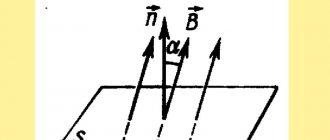
Now consider the general case when the vector forms an angle with the normal to the contour plane (Fig. 2).
Rice. 2.
We see that now only the perpendicular component of the magnetic induction vector “flows” through the circuit (and the component that is parallel to the circuit does not “flow” through it). Therefore, according to formula (1), we have . But, therefore
(2)
This is the general definition of magnetic flux in the case of a uniform magnetic field. Note that if the vector is parallel to the plane of the loop (that is), then the magnetic flux becomes zero.
How to determine magnetic flux if the field is not uniform? Let's just point out the idea. The contour surface is divided into a very large number of very small areas, within which the field can be considered uniform. For each site, we calculate its own small magnetic flux using formula (2), and then we sum up all these magnetic fluxes.
The unit of magnetic flux is weber
(Wb). As we see,
Wb = T · m = V · s. (3)
Why does magnetic flux characterize the “number of lines” of the magnetic field penetrating the circuit? Very simple. The “number of lines” is determined by their density (and therefore their size - after all, the greater the induction, the denser the lines) and the “effective” area penetrated by the field (and this is nothing more than ). But the multipliers form the magnetic flux!
Now we can give a clearer definition of the phenomenon of electromagnetic induction discovered by Faraday.
Electromagnetic induction
- this is the phenomenon of the occurrence of electric current in a closed conducting circuit when the magnetic flux passing through the circuit changes
.
Electric field energy
When charging a capacitor, energy is stored in the form of electric field energy and can be returned to the source when converted into another form of energy.
Expressing energy through capacitor characteristics
The charge of a capacitor is formed by the transfer of charged particles from one plate to another under the influence of an external energy source. The work done when transferring a unit of charge is numerically equal to the voltage between the plates. If the voltage did not change during the charging process, then the energy could be determined by the product of voltage and charge [see. formula (1.5)]. However, during the process of charge accumulation, the voltage also increases, therefore, when determining the energy spent on the formation of a charge, it is necessary to take into account the relationship between voltage and charge (7.28). If the capacitance of the capacitor is a constant value, the relationship between voltage and charge is graphically expressed by a straight line (Fig. 11.1).
Rice. 11.1. Towards the determination of electric field energy
Let us assume that the charge on Q1 has increased by dQ, a value so small that within the limits of the change in charge, the voltage can be considered unchanged:
Expressing energy through electric field characteristics
Expression (11.2) was obtained based on the law of conservation of energy; however, it does not directly follow from it that the energy We is the energy of the electric field. It can be shown that this energy is distributed in an electric field. For example, consider the uniform electric field of a flat capacitor (see Fig. 1.6, a).
The flow of the electric displacement vector through any surface held in the dielectric parallel to the plates is equal to the charge Q of the capacitor, which follows from formula (7.33): DS = Q. The strength of the uniform electric field E = U/l. Therefore, where V is the volume of the dielectric in which the field associated with the charged plates of the capacitor is distributed. The ratio of energy to the volume of the dielectric gives the volumetric energy density of the electric field: The energy defined by formula (11.2) through the characteristics of conductors is also expressed by formula (11.5) through the characteristics of the electric field. The equivalence of these formulas indicates that the energy of a system of charged bodies is the energy of an electric field.
Problem 11.1.
A flat air capacitor with a capacity of 600 pF with a distance between the electrodes of 2 cm is charged to a voltage of U = 4 kV and is disconnected from the voltage source. Determine the change in energy and electric field strength of the capacitor when the distance between the electrodes is halved. Solution. Before changing the distance between the plates, the electric field energy, according to formula (11.3), Electric field strength [see. (1.5)] When the distance between the plates is halved, the capacitance of the capacitor according to formula (7.29) doubles. In this case, the charge of the capacitor does not change (it is assumed that there is no charge leakage). Due to an increase in the capacitance of the capacitor, the voltage between the plates will decrease by the same amount [see. formula (7.28)]: Electric field energy Electric field strength
Mechanical forces in an electric field
Let us consider the question of mechanical forces in an electric field using the example of a flat capacitor charged from an external energy source having a voltage U. We will assume that the electric field of the capacitor is uniform.
Energy balance in an electrostatic system
The forces Fe arising as a result of the interaction of the plates with the electric field are applied to the plates and are directed so that they attract. Let us assume that one of the capacitor plates is free, and its possible small movement under the influence of the force Fe will be denoted by dx (Fig. 11.2). Rice. 11.2. Mechanical forces in an electric field
In further discussions, we will proceed from the fact that when the charge of the capacitor changes, there is no energy loss in the conductors due to the movement of charged particles and in the dielectric due to changes in the field strength.
Under such conditions, in accordance with the law of conservation of energy, when the charge of the capacitor changes by dQ due to the energy of an external source, the energy of the electric field changes by dWe and mechanical work Fedx is performed:
Generalized expression of electric force (first case)
The charge of the capacitor remains unchanged (Q = const), i.e. the charged capacitor is disconnected from the external energy source. At dQ = 0, the work of the external source is UdQ = 0. Therefore, or The last equality shows that the mechanical work associated with the movement of the plate is performed due to the energy of the electric field. Indeed, the mechanical work done by the electric force is positive (Fedх > 0), therefore, the change in the energy of the electric field is negative (dWe
The mechanical force tending to change the position of the capacitor plate can be expressed by the relation. Reasoning in a similar way, we can obtain the relationship between the mechanical moment and the angle of rotation α, if the mechanical movement is carried out in the form of rotation of one plate relative to the other: Changing the distance l between the plates by dx will change the capacitance of the capacitor . As the distance decreases, the capacitance increases, and the voltage between the plates decreases, which directly follows from formula (7.28).
Let us assume that the distance between the plates increases due to the action of external mechanical forces on the plates. The energy in the system increases by the amount of work done by an external source of mechanical energy. In this case, the capacitance of the capacitor will decrease, and the voltage between the plates will increase.
Generalized expression of electric force (second case)
The voltage between the plates remains constant (U = const), i.e., while the plate is moving, the capacitor is not disconnected from the external energy source.
As the distance between the plates decreases, the capacitance of the capacitor increases, which, at a constant voltage, entails an increase in charge.
An external energy source must expend energy to increase the charge of the capacitor in the amount of UdQ.
The change in electric field energy dWe when the charge changes, according to formula (11.2), i.e., is half the energy of the external source consumed when the capacitor charge increases. The second half of the energy is spent on covering the mechanical work Fedh, therefore, Hence Similarly, with rotational motion
An increase in the distance between the plates as a result of external mechanical forces will lead to a decrease in capacity. But at a constant voltage, a decrease in capacitance will be followed by a decrease in the charge of the capacitor and a decrease in the energy of the electric field. In this case, the mechanical work associated with the movement of the plate is performed by external mechanical forces. The magnitude of this work is numerically equal to the decrease in the energy of the electric field. Thus, energy is returned to the source of electrical energy that is numerically equal to twice the value of mechanical work.
induced emf
What is the mechanism by which induced current occurs? We will discuss this later. So far, one thing is clear: when the magnetic flux passing through the circuit changes, some forces act on the free charges in the circuit - external forces
, causing the movement of charges.
As we know, the work of external forces to move a single positive charge around a circuit is called electromotive force (EMF): . In our case, when the magnetic flux through the circuit changes, the corresponding emf is called induced emf
and is designated .
So, induced emf is the work of external forces that arise when the magnetic flux through a circuit changes, moving a single positive charge around the circuit
.
We will soon find out the nature of the external forces arising in this case in the circuit.
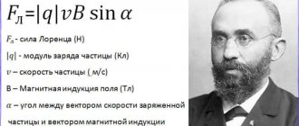
Basic formulas for calculating the MI vector
The magnetic induction vector, the formula of which is B = Fm / I * ∆L, can be found using other mathematical calculations.
Law of Electromagnetic Induction
The law of electromagnetic induction (Faraday's law) sounds like this:
The induced emf in a closed loop is equal and opposite in sign to the rate of change of the magnetic flux on the surface bounded by the ring.
Mathematically, this can be described by the formula:
| Faraday's law Ɛi – induced emf B ΔФ / Δt – rate of change of magnetic flux W/s |
The “-” sign in the formula allows you to take into account the direction of the induction current. The induced current in a closed circuit is always directed in such a way that the magnetic flux of the field created by this current through the surface bounded by the ring reduces those field changes that cause the appearance of the induced current.
If the circuit consists of N turns (i.e. it is a coil), the induced emf will be calculated as follows.
| Faraday's law for a circuit of N turns Ɛi – induced emf B ΔФ / Δt – rate of change of magnetic flux W/s N – number of revolutions |
The strength of the induction current in a closed conductive circuit with resistance R:
| Ohm's law for a conducting circuit Ɛi – induced emf B I – induction current strength [A] R – circuit resistance [Ohm] |
If a conductor of length l moves with speed v in a constant uniform magnetic field with induction B, the emf of electromagnetic induction will be equal to:
| Induction EMF for a moving conductor Ɛi – induced emf B B – magnetic induction [T] v – conductor speed [m/s] l – core length [m] |
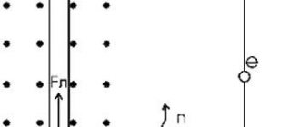
The appearance of an inductive electromagnetic field in a conductor moving in a magnetic field is explained by the action of the Lorentz force on free charges in moving conductors. In this case, the Lorentz force plays the role of an external force.
A conductor moving in a magnetic field through which an induced current flows experiences magnetic braking. The total work done by the Lorentz force is zero.
The amount of heat in the circuit is released both due to the work of an external force, which keeps the speed of the conductor constant, and due to a decrease in the kinetic energy of the conductor.
A change in the magnetic flux entering a closed loop can occur for two reasons:
- due to the movement of a circuit or its parts in a constant magnetic field over time. This is the case when conductors, and with them free charge carriers, move in a magnetic field
- due to changes in time of a magnetic field with a stationary circuit. In this case, the occurrence of induced emf can no longer be explained by the action of the Lorentz force. The phenomenon of electromagnetic induction in stationary conductors, which occurs when the surrounding magnetic field changes, is also described by Faraday's formula
Consequently, the phenomena of induction in moving and stationary conductors proceed in the same way, but the physical reason for the occurrence of induction current in these two cases turns out to be different:
- in the case of moving conductors, the induced emf arises due to the Lorentz force
- in the case of stationary conductors, the induced emf is a consequence of the action of the vortex electric field on free charges, which occurs when the magnetic field changes.
Biot-Savart-Laplace Law
EMF induction formula
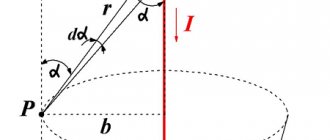
Describes the rules for finding a B → magnetic field that creates a direct electric current. This is an experimentally established model. Biot and Savard showed this in practice in 1820, Laplace was able to formulate it. This law is fundamental in magnetostatics. In practice, a fixed wire of small cross-section was considered, through which an electric current was passed. For the study, a small section of wire was selected, which was characterized by the vector dl. Its module corresponded to the length of the section under consideration, and its direction coincided with the direction of the current.
Interesting. Laplace Pierre Simon also proposed to consider the movement of an electron as a current and, based on this statement, using this law, proved the possibility of determining the MF of an advancing point charge.
According to this physical rule, each segment dl of a conductor through which electric current I flows forms a magnetic field dB in the space around itself with an interval r and at an angle α:
dB = µ0 * I * dl * sin α / 4 * π * r2,
where is it:
- dB – magnetic induction, T;
- µ0 = 4 π * 10-7 – magnetic constant, H/m;
- I – current strength, A;
- dl – core section, m;
- r – distance from the point where the magnetic induction is located, m;
- α is the angle formed by r and the vector dl.
Important! According to the Biot-Savart-Laplace law, by summing the magnetic field vectors of individual sectors, it is possible to determine the MF of the required current. It will be equal to the vector sum.
Biot-Savart-Laplace Law
There are formulas that describe this law for individual cases of MP:
- fields of direct electron motion;
- fields of circular motion of charged particles.
Formula of the deputy of the first kind:
B = µ * µ0 * 2 * I / 4 * π * r.
For a circular motion it looks like this:
B = µ * µ0 * I / 4 * π * r.
In these formulas, µ is the (relative) magnetic permeability of the medium).
The law under consideration follows from Maxwell's equations. Maxwell derived two equations for the magnetic field; the case where the electric field is constant was just considered by Biot and Savart.
Superposition principle
For MF, there is a principle according to which the total vector of magnetic induction at a certain point is equal to the vector sum of all vectors MI created by different currents at a given point:
B → = B1 → + B2 → + B3 →… + Bn→
Lenz's rule
To determine the direction of the induction current, it is necessary to use Lenz's rule.
From an academic point of view, this rule sounds like this: the induced current excited in a closed circuit when the magnetic flux changes is always directed so that the magnetic field it creates prevents the change in the magnetic flux, causing an induced current.
Let's try a little simpler: the coil in this case is a disgruntled grandmother. They take away the magnetic flux: she is unhappy and creates a magnetic field, which this magnetic flux wants to restore.
They give her magnetic flux, they accept it, they talk, they use it, and she's like, “Because your magnetic flux has surrendered to me!” and creates a magnetic field that displaces this magnetic flux.
Faraday's law of electromagnetic induction
The strength of the induction current in Faraday's experiments turned out to be greater, the faster the magnetic flux through the circuit changed.
If in a short time the change in magnetic flux is equal to , then the speed
changes in magnetic flux are a fraction (or, which is the same, the derivative of magnetic flux with respect to time).
Experiments have shown that the strength of the induction current is directly proportional to the magnitude of the rate of change of the magnetic flux:
The module is installed in order not to be associated with negative values for now (after all, when the magnetic flux decreases, it will be ). Subsequently we will remove this module.
From Ohm's law for a complete chain we at the same time have: . Therefore, the induced emf is directly proportional to the rate of change of the magnetic flux:
(4)
EMF is measured in volts. But the rate of change of magnetic flux is also measured in volts! Indeed, from (3) we see that Wb/s = V. Therefore, the units of measurement of both parts of proportionality (4) coincide, therefore the proportionality coefficient is a dimensionless quantity. In the SI system it is set equal to unity, and we get:
(5)
This is the law of electromagnetic induction
or
Faraday's law
. Let's give it a verbal formulation.
Faraday's law of electromagnetic induction
.
When the magnetic flux penetrating a circuit changes, an induced emf appears in this circuit equal to the modulus of the rate of change of the magnetic flux
.
Current circuit and inductor
The current circuit can be single (single-turn coil)
The current circuit can consist of several circuits (multi-turn coil)
In electrical engineering and radio engineering, multi-turn coils are used.
The more turns, the greater the inductance of the coil. The same current flowing through a single turn and through a multi-turn coil will create a magnetic field of different strengths. A multi-turn coil has more inductance than a single turn; it is proportional to the number of turns.
When it is necessary to create a strong magnetic field, hundreds and thousands of turns of thin copper wire are wound. Such coils are used in electromagnets, transformers, and electric motors.
Lenz's rule
We will call the magnetic flux, a change in which leads to the appearance of an induction current in the circuit, external magnetic flux
.
And we will call the magnetic field itself, which this magnetic flux creates, external magnetic field
.
Why do we need these terms? The fact is that the induction current arising in the circuit creates its own
a magnetic field that, according to the principle of superposition, is added to an external magnetic field.
Accordingly, along with the external magnetic flux, its own
magnetic flux created by the magnetic field of an induction current.
It turns out that these two magnetic fluxes - internal and external - are interconnected in a strictly defined way.
Lenz's rule
.
The induced current always has a direction such that its own magnetic flux prevents a change in the external magnetic flux
.
Lenz's rule allows you to find the direction of the induced current in any situation.
Let's look at some examples of applying Lenz's rule.
Let us assume that the circuit is penetrated by a magnetic field, which increases with time (Fig. (3)). For example, we bring a magnet closer to the contour from below, the north pole of which in this case is directed upward, towards the contour.
The magnetic flux through the circuit increases. The induced current will be in such a direction that the magnetic flux it creates prevents the increase in external magnetic flux. To do this, the magnetic field created by the induction current must be directed against
external magnetic field.
The induced current flows counterclockwise when viewed from the direction of the magnetic field it creates. In this case, the current will be directed clockwise when viewed from above, from the side of the external magnetic field, as shown in (Fig. (3)).
Rice. 3. Magnetic flux increases
Now suppose that the magnetic field penetrating the circuit decreases with time (Fig. 4). For example, we move the magnet downward from the loop, and the north pole of the magnet points toward the loop.
Rice. 4. Magnetic flux decreases
The magnetic flux through the circuit decreases. The induced current will have a direction such that its own magnetic flux supports the external magnetic flux, preventing it from decreasing. To do this, the magnetic field of the induction current must be directed in the same direction
, as the external magnetic field.
In this case, the induced current will flow counterclockwise when viewed from above, from the side of both magnetic fields.
How is the laziness rule formulated?
LENZ'S RULE - LENZ'S RULE, an electromagnetic law derived by Russian physicist Heinrich Lenz (1804 65) in 1834. The law states that an induced electric current flows in the direction opposite to the charge that produced the current. see also INDUCTION ... Scientific and technical encyclopedic dictionary
Lenz's rule - - [Ya.N.Luginsky, M.S.Fezi Zhilinskaya, Yu.S.Kabirov. English-Russian dictionary of electrical engineering and electrical power engineering, Moscow, 1999] Topics of electrical engineering, basic concepts EN law of induced current Lenz s law Lenz s rule ... Technical Translator's Guide
Lenz's rule - a rule that determines the direction of induction currents (arising during electromagnetic induction); a consequence of the law of conservation of energy. According to Lenz’s rule, the induced current arising in a closed circuit is directed in such a way that... ... Encyclopedic Dictionary of Metallurgy
Lenz's rule - Lenco taisyklė statusas T sritis fizika atitikmenys: engl. Lenz's law; Lenz's rule vok. Lenzsche Regel, f; Lenzsches Gesetz, n rus. Lenz's law, m; Lenz's rule, n pranc. loi de Lenz, f … Fizikos terminų žodynas
LAZY RULE - determines the direction of the flow. currents arising as a result of electromagnetic induction; is a consequence of the law of conservation of energy. L. p. established (1833) by E. H. Lenz. Induction the current in the circuit is directed so that the flow it creates ... ... Physical encyclopedia
- RULE - (1) The gimlet determines the direction of the magnetic field strength vector of a straight conductor with direct current. If a gimlet is screwed in in the direction of the current, then the direction of its rotation determines the direction of the magnetic lines of force... ... Big Polytechnic Encyclopedia
- Lenz's rule - Lenz's rule, a rule for determining the direction of the induction current: The induction current arising from the relative movement of the conducting circuit and the source of the magnetic field always has a direction such that its own magnetic flux ... ... Wikipedia
- right hand rule - an easy-to-memorize rule for determining the direction of induced current in a conductor moving in a magnetic field: if you position your right palm so that the thumb behind it coincides with the direction of movement... ... Encyclopedic Dictionary of Metallurgy
Laminate carpet or linoleum, which is better?
- phase rule is an equation connecting the number of degrees of freedom (C) of a thermodynamic system with the number of components (K) and the number of equilibrium phases (F): C = K F + 2. If the influence of pressure on phase equilibrium can be neglected, then the phase rule has the form: ... ... Encyclopedic Dictionary of Metallurgy
- lever rule - the rule of segments is one of the manifestations of the law of conservation of mass of a substance, which establishes the relationship between the chemical compositions and masses of two substances and the 3rd substance formed from the first two; serves to determine from a diagram ... Encyclopedic Dictionary of Metallurgy
- The whole world is in your hands - everything will be the way you want it
Interaction of a magnet with a circuit
So, the approach or removal of a magnet leads to the appearance of an induced current in the circuit, the direction of which is determined by Lenz’s rule. But the magnetic field acts on the current! An Ampere force will appear acting on the circuit from the magnetic field. Where will this force be directed?
If you want to have a good understanding of Lenz's rule and the determination of the direction of the Ampere force, try answering this question yourself. This is not a very simple exercise and an excellent task for C1 on the Unified State Exam. Consider four possible cases.
1. We bring the magnet closer to the circuit, the north pole is directed towards the circuit. 2. We remove the magnet from the circuit, the north pole is directed towards the circuit. 3. We bring the magnet closer to the circuit, the south pole is directed towards the circuit. 4. We remove the magnet from the circuit, the south pole is directed towards the circuit.
Do not forget that the magnetic field is not uniform: the field lines diverge from the north pole and converge towards the south. This is very important for determining the resulting Ampere force. The result is as follows.
If you bring the magnet closer, the circuit is repelled from the magnet. If you remove the magnet, the circuit is attracted to the magnet. Thus, if the circuit is suspended on a thread, then it will always deviate in the direction of the movement of the magnet, as if following it. The location of the magnet poles does not matter in this case.
.
In any case, you should remember this fact - what if such a question comes up in part A1
This result can be explained from completely general considerations - using the law of conservation of energy.
Let's say we bring the magnet closer to the circuit. An induction current appears in the circuit. But to create a current, work must be done! Who does it? Ultimately, we are, moving the magnet. We perform positive mechanical work, which is converted into positive work of external forces arising in the circuit, creating an induced current.
So our work to move the magnet should be positive
.
This means that when we bring the magnet closer, we must overcome
the force of interaction between the magnet and the circuit, which, therefore, is a
repulsive
.
Now remove the magnet. Please repeat these arguments and make sure that an attractive force should arise between the magnet and the circuit.
Magnetic field energy
A magnetic field has energy. Magnetic forces perform mechanical work by attracting or repelling other magnets or bodies made of magnetic materials. The changing magnetic field induces an electric current in the conductors.
Magnetic energy can be expressed through a mathematical formula. In the previous section, the inertia of an inductive circuit was mentioned; its role in electromagnetic phenomena was compared with the role of mass in mechanics. Interestingly, this analogy deepens when considering energy.
The formula for magnetic field energy is similar to the formula for the kinetic energy of a mechanical body:
The energy of the magnetic field is proportional to the inductance and the square of the current.
During the transient process, when the current in the circuit slowly increases when turned on, magnetic energy accumulates. This energy can be used to do work. And this energy creates problems when turning off the current in a circuit with high inductance.
If the current is reduced, an emf will arise, slowing down the decrease in current. But if the current is turned off, abruptly breaking the circuit, the rate of change of the current from a specific value to zero should theoretically be infinitely large. This means that the self-induction EMF when the current is turned off should also be infinitely large.
This mathematical paradox arose from simplified, idealized formulas. In reality, the current does not stop instantly, opening the contacts takes a short period of time, but still the rate of change of the current is high, and an emf of significant magnitude is induced. A common occurrence when a circuit is switched off is sparking. If you turn off the current in a circuit with high inductance, then an attempt to abruptly stop the current can cause an electric arc to flash.
What happens if the arc does not flash and the current stops? Where did the magnetic field energy go? Partially it turned into thermal energy - the contacts of the switch heated up. The rest of the magnetic field energy, when it sharply decreased to zero, turned into an electromagnetic wave. The alternating magnetic field induced an alternating electric field; in turn, the alternating electric caused a new wave of the magnetic, and so on.
Turning off the current by simply flicking a switch sends a wide “noise” spectrum of electromagnetic vibrations into infinite space.
Faraday's Law + Lenz's Rule = Module Removal
Above we promised to remove the module in Faraday’s law (5). Lenz's rule allows us to do this. But first we will need to agree on the sign of the induced emf - after all, without the module on the right side of (5), the magnitude of the emf can be either positive or negative.
First of all, one of two possible directions for traversing the contour is fixed. This direction is declared positive
.
The opposite direction of traversing the contour is called negative
. Which direction of traversal we take as positive does not matter - it is only important to make this choice.
Magnetic flux through a loop is considered positive if the magnetic field penetrating the loop is directed in the direction from which the circuit is traversed in the positive direction counterclockwise. If, from the end of the magnetic induction vector, the positive direction of the round is seen clockwise, then the magnetic flux is considered negative.
Induction emf is considered positive if the induced current flows in a positive direction. In this case, the direction of external forces arising in the circuit when the magnetic flux through it changes coincides with the positive direction of bypassing the circuit.
On the contrary, induced emf is considered negative if the induced current flows in a negative direction. In this case, external forces will also act along the negative direction of the circuit bypass.
So, let the circuit be in a magnetic field. We fix the direction of the positive circuit bypass. Let's assume that the magnetic field is directed there, looking from where the positive detour is made counterclockwise. Then the magnetic flux is positive: .
Let us further assume that the magnetic flux increases. According to Lenz's rule, the induced current will flow in the negative direction (Fig. 5).
Rice. 5. Magnetic flux increases
Therefore, in this case we have . The sign of the induced emf turned out to be opposite to the sign of the rate of change of the magnetic flux. Let's check this in another situation.
Namely, let us now assume that the magnetic flux decreases. According to Lenz's rule, the induced current will flow in the positive direction. Therefore, (Fig. 6).
Rice. 6. Magnetic flux increases
This is, in fact, a general fact: given our agreement on the signs, Lenz’s rule always leads to the fact that the sign of the induced emf is opposite to the sign of the rate of change of the magnetic flux
:
(6)
Thus, the modulus sign in Faraday’s law of electromagnetic induction is eliminated.
Magnetic induction
According to progressive scientific ideas about electrical phenomena, MF is inextricably linked with current and cannot be present without it . It is impossible to assume electric current without MF. Including in the case of a permanent magnet, this background is associated with molecular lines.
If a needle is placed in the place where the MP is located, it tends to borrow a certain state, which actually shows the orientational qualities of the MP. The coordinated direction at this place point must take into account the destination, where the axis is mounted - a freely suspended infinitesimal magnetic needle whose middle is aligned with the starting place point. In this case, out of 2 possible directions along the axis of the MP arrow, the assignment from the southern end to the north is symbolically assigned.
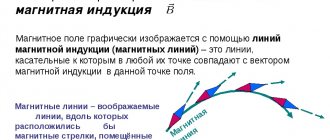
You can get a clearer idea of the direction of the field if there is a series of lines where the axes of all the arrows are relatively tangent. These parts are called magnetic lines.
A set of rows is referred to as MP. If we infinitely reduce the area of the contour, attracting it to a point, we can come to the expression for the infinitesimal stage d, T is active in the contour of the small region s, where the angle P has a specific value between the normality to the plane and the small contour. In this case, the direction of the field will be the point where the small outline is located.
Vortex electric field
Let us consider a stationary circuit located in an alternating magnetic field. What is the mechanism for the occurrence of induction current in the circuit? Namely, what forces cause the movement of free charges, what is the nature of these external forces?
Trying to answer these questions, the great English physicist Maxwell discovered a fundamental property of nature: a magnetic field changing over time generates an electric field
. It is this electric field that acts on free charges, causing an induced current.
The lines of the resulting electric field turn out to be closed, and therefore it was called a vortex electric field
. The vortex electric field lines go around the magnetic field lines and are directed as follows.
Let the magnetic field increase. If there is a conducting circuit in it, then the induced current will flow in accordance with Lenz’s rule - clockwise, if viewed from the end of the vector. This means that the force acting from the vortex electric field on the positive free charges of the circuit is also directed there; This means that the vector of the vortex electric field intensity is directed exactly there.
So, the lines of intensity of the vortex electric field are directed in this case clockwise (looking from the end of the vector , (Fig. 7).
Rice. 7. Vortex electric field with increasing magnetic field
On the contrary, if the magnetic field decreases, then the lines of intensity of the vortex electric field are directed counterclockwise (Fig. 8).
Rice. 8. Vortex electric field with decreasing magnetic field
Now we can better understand the phenomenon of electromagnetic induction. Its essence lies precisely in the fact that an alternating magnetic field generates a vortex electric field. This effect does not depend on whether a closed conducting circuit is present in the magnetic field or not; With the help of a circuit we only detect this phenomenon by observing the induced current.
The vortex electric field differs in some properties from the electric fields already known to us: the electrostatic field and the stationary field of charges that form a direct current.
1. The vortex field lines are closed, while the electrostatic and stationary field lines begin on positive charges and end on negative ones. 2. The vortex field is nonpotential: its work on moving a charge along a closed loop is not zero. Otherwise, the vortex field could not create an electric current! At the same time, as we know, electrostatic and stationary fields are potential.
So, induced emf in a stationary circuit is the work of a vortex electric field to move a unit positive charge around the circuit
.
Let, for example, the circuit be a ring of radius and penetrated by a uniform alternating magnetic field. Then the intensity of the vortex electric field is the same at all points of the ring. The work force with which the vortex field acts on the charge is equal to:
Therefore, for the induced emf we obtain:
An accurate experiment was carried out to measure persistent current in a metal ring
Rice. 1.
The magnetic flux in a metal ring with a diameter of about 1 micron induces a persistent current. At a temperature of about 1 K, the current value is approximately 1 nA (nanoampere). The direction of the current is chosen arbitrarily. Drawing by Yu. Erin
In 1983, theoretical physicists put forward a hypothesis according to which a magnetic flux penetrating a metal ring with a diameter of about 1 micron should create an undamped current - the so-called persistent current. The reasons for its occurrence have nothing to do with superconductivity and lie in the quantum features of the movement of some electrons in the metal. Several theories of persistent current have been proposed that predict its magnitude and direction. However, the small value of such a continuous current does not allow its value to be accurately measured and compared with existing theoretical models. A group of American and German scientists, thanks to their original experimental setup, for the first time managed to very accurately measure the magnitude of the persistent current in a metal ring. Their result should help physicists identify the correct model for describing this phenomenon.
What is resistance?
Everyone knows that electric current in matter is the directed movement of free charged particles. In a metal, current is created by free electrons—electrons located in the outermost orbits of an atom and weakly bound to the atomic nucleus. In order for directional movement to occur, it is necessary to create a potential difference or voltage at the ends of the conductor. The voltage-induced electric field in the metal causes electrons to diffuse through it. Moving charged particles collide, lose part of their energy and are scattered by ions, various defects, inhomogeneities of the crystal lattice and impurities in the substance. This dissipative (i.e., accompanied by a decrease in energy) scattering leads to the appearance of resistance.
If electrons are considered as particles that obey the classical laws of physics in their movement, then by writing Newton’s second law, we can obtain a mathematical relationship between the density of the current flowing through the metal and the electrical voltage causing its flow. Simply put, we can theoretically derive Ohm's experimental law. This is how, at the beginning of the 20th century, Paul Drude received the theory of electronic conductivity of metals and, in particular, the famous formula for resistance, named after him (see Drude Theory). One of the main characteristics in Drude's theory was the length and time of free travel of electrons in a metal between collisions with “interference.” Since Drude's formula described the resistance of conductors well, it practically did not change even when quantum mechanics appeared.
In the 70s, negative magnetoresistance was discovered - a decrease in the resistance of a conductor with an increase in the magnetic field induction. This discovery did not fit into the framework of Drude's theory. In 1979, American and Soviet physicists established that it is necessary to add a term related to the quantum behavior of the electron to the classical resistance formula, since the electron, according to the well-known principle of dualism, is not only a particle, but also a wave. In other words, resistance must be explained not only by the collision of particles, but also by taking into account the so-called effects of quantum interference of electron waves.
A year later, Boris Altshuler and his colleagues built a quantitative theory of this phenomenon, which explained, in particular, negative magnetoresistance. In their article, in addition to the already known classical quantities, such as the time and mean free path of electrons, new characteristics appeared to describe resistance - the time and length of phase coherence of electrons. The phase coherence length is the distance of non-dissipative scattering of an electron, that is, the distance that an electron wave or electron travels without experiencing inelastic scattering (without losing its original energy). Phase coherence time is the time between inelastic collisions of an electron, or the time during which an electron wave does not lose its energy. From the definition it follows that at such a length the electron makes a zero contribution to the total resistance of the metal.
A decrease in temperature suppresses the probability of an inelastic collision of an electron wave and, accordingly, the probability of a decrease in the electron energy, which is reflected at the macroscopic level in the form of a decrease in resistance. Consequently, the lower the temperature, the longer the time and length of phase coherence. For example, at the temperature of liquid helium (about 4 K), the phase coherence scale is approximately one micrometer for many metals.
The reader may have a question: how does the Drude electron mean free path differ from the phase coherence length, which at first glance has the same physical meaning? The thing is that in classical theory it does not matter at all whether an electron collides with an ion, defect, etc. elastically or not. Any electron scattering is interpreted as an event leading to an increase in the resistance of the substance. In the quantum approach, electrons within the phase coherence length elastically collide with obstacles in their path and do not change their energy until a certain moment, until the probability of an inelastic collision with interference becomes significant.
Persistent currents and causes of their occurrence
Quantum corrections to resistivity were noticed in 1983 by physicists Rolf Landauer, Markus Büttiker and Joseph Imrie, who published in the journal Physics Letters A
interesting hypothesis. What happens if you take a metal wire with a length and cross-sectional area less than or equal to the phase coherence length, close it in a ring, cool it to low temperatures and then penetrate it with a magnetic flux (Fig. 1)?
Scientists have come to the conclusion that undamped currents will begin to flow in such a ring, which have nothing in common with the currents in superconductors. They were called persistent currents (from the English persistent
"constant"). The magnetic field plays an important role here. The fact is that electrons move with equal probability in the ring either clockwise or counterclockwise, that is, on average, the current in the ring is zero. To destroy this symmetry and set a specific direction for the movement of electrons is the main task of the magnetic field.
Note that the differences between superconducting and persistent currents are very significant. As already mentioned, an electron can move without resistance within the phase coherence length. In a superconductor, due to the combination of electrons into pairs, or more precisely, into Cooper pairs, their length and phase coherence time are equal to infinity. They move without resistance for as long as desired and for as long a distance as desired. Moreover, a superconducting current is created by absolutely all conduction electrons of the metal.
In the case of persistent current, no pairing of particles occurs. A persistent current is created only by those electrons for which there is the greatest probability of unhindered movement within the phase coherence length. Some particles, even within the limits of phase coherence, are not able to move without losing their energy. By lowering the temperature, we not only increase the phase coherence length, but also increase the probability of more electrons passing through obstacles without dissipation. However, there are still particles for which this task is insurmountable.
The described phenomenon seems incredible, but let's remember that the movement of an electron around an atomic nucleus can also be interpreted as an undamped current. Roughly speaking, a similar picture is observed in a metal ring.
At the macroscopic level, the difference between these two types of currents is that the magnitude of the current persistent current does not depend on the cross-sectional area of the ring. Moreover, the superconducting current in a ring with the same dimensions will be much greater than the persistent current in it. It is also interesting to note here the fact that persistent current exists in the ring, which actually has resistance. Nothing prevents you from connecting a power source to the ring and thereby causing current to flow through it. Simply, the total current will be the sum or difference of the normal current coming from the battery and the persistent current (it all depends on the direction of flow of the normal current).
The miracles don't end there. Theorists, among other things, have shown that the value of the persistent current oscillates depending on the magnetic flux passing through the ring. The period of such oscillations is equal to the ratio of two fundamental constants - Planck’s constant h
and electron charge
e
(
h
/
e
= 4.1·10–15 T·m2).
In physics, the ratio h
/
e
is called a magnetic flux quantum -
fluxoid
(in superconductivity, the fluxoid is 2 times smaller:
h
/
2e
; the two arises due to the combination of electrons into Cooper pairs). The maximum value of the persistent current (maximum amplitude) will be observed when the magnetic flux through the ring is an integer number of fluxoids. If the magnetic flux is a multiple of half the fluxoid, then a persistent current will not arise.
Despite the fact that the reasons for the occurrence of persistent currents are no longer in doubt, the theory of these currents has not yet been fully constructed. Firstly, there is no clear formula that determines the amount of persistent current in the ring. Secondly, although it is clear that the direction of current flow depends on the number of electrons involved in this movement, theorists cannot accurately predict which way it will flow. Everything is based only on rough estimates. Thus, for a temperature of 1 K in a ring with a diameter of about 1 μm (this corresponds to the phase coherence length at a temperature of 1 K), the amplitude of the persistent current should be on the order of one nanoampere (10–9 A).
To date, several plausible theoretical models have been put forward to describe this effect. Each of them predicts periodicity from the magnetic flux, and each gives results that are the same order of magnitude as the 10–9 A above. But all models differ greatly in the number before the power of 10–9. Therefore, it is possible to find out which theory quantitatively correctly describes the phenomenon of persistent current only by conducting experiments to most accurately measure its value.
I would like to emphasize that the reasons causing the emergence of persistent currents are exclusively of a quantum nature. This also applies to the magnetic flux passing through the ring. The “classical” influence of the magnetic field in the form of the Lorentz force acting on all moving charged particles is insignificant. Without going into details, let's give a clear example. Let the magnetic flux through a ring with a diameter of the order of 1 micron be created using a long solenoid with a diameter of, say, 0.5 microns. Its location is such that the plane of the ring is perpendicular to the axis of the solenoid and intersects its middle. Outside the solenoid the induction is zero and the magnetic field has virtually no effect on the ring. This would be the case in classical physics. However, according to quantum mechanics, the dynamics of electrons is not determined by the induction of the field, but by its so-called vector potential, which is not equal to zero outside the solenoid. Generally speaking, the situation described here is known in physics as an example of the Aharonov–Bohm effect. Thus, we can say that the appearance of persistent currents in the ring is due to two reasons: phase coherence of electrons and the Aharonov-Bohm effect.
Experiments to observe and measure persistent currents
In the first part of the news it was said that at very low temperatures the phase coherence length is approximately 1 micron. This means that by making a ring with a circumference of about a micrometer and cooling it to helium temperatures, it is possible to observe and measure an undamped persistent current.
However, as often happens, technical problems arose. First of all, the metal must not be superconducting at low temperatures. There are such materials - gold, copper and silver - so, in principle, the issue with the material is resolved. Another problem is the impossibility of directly soldering an ammeter, and even a microscopic one, into the ring in order to measure persistent current. There are simply no such ammeters, and the current is so low (about 1 nA) that it is outside the measuring range of the most accurate measuring instruments of this class. Then scientists took a different path. The emerging continuous current can be measured using special, very sensitive magnetometers - SQUIDs. From the recorded magnitude of the magnetic field created by persistent currents, it is then easy to reconstruct the current value corresponding to the observed field.
Using this technique, a group of scientists from the Bell Laboratory led by Laurent Levy - 7 years after the publication of the work of Büttiker, Landauer and Imrie - conducted the first experiment in 1990 to observe and measure persistent currents on an array (about 100 thousand pieces) small, approximately 0.5 μm in diameter, copper rings (see LP Lévy, G. Dolan, J. Dunsmuir, H. Bouchiat. Magnetization of mesoscopic copper rings: Evidence for persistent currents // Phys. Rev. Lett.
64, 2074–2077). The result was disappointing: there are persistent currents, they really depend on the magnetic flux through the rings, and their value oscillates with a period equal to one fluxoid. But even the SQUID was unable to accurately measure their value - the sensitivity of the magnetometer of the Levy group was at the level of the measured value. In addition, strong interference arose due to magnetic impurities in the substance, which are always present even in a very pure ring.
Later, new attempts were made, under the leadership of other scientists, to measure persistent currents using the same SQUIDs, but in all experiments the scatter of data was so great that it often varied by orders of magnitude. The only achievement was confirmation of the presence of current oscillations with a period h/e
. It became clear that the instrumental error of existing magnetometers does not allow accurately measuring the observed effect.
And recently in Science
a joint article by American and German scientists appeared, Persistent Currents in Normal Metal Rings, which originally studied persistent currents in arrays of aluminum rings with a diameter of about 1 micron. The design they proposed makes it possible to measure the magnitude of persistent currents with unprecedented accuracy - 250 times more accurate than what was possible using SQUID magnetometers. For the first time, the accuracy of persistent current measurements was sufficient to verify the correctness of existing theoretical models.
The experimental setup of the authors of the article was a silicon wafer - a cantilever - on which 1680 rings with the same diameter of 308 nm were deposited lithographically (see Electron lithography) (Fig. 2). The entire system was cooled to a temperature below 1 K and placed in a magnetic field of the order of 1 T (such a huge value of magnetic induction did not allow the rings to go into a superconducting state at this temperature, despite the fact that aluminum becomes a superconductor already at 1.2 K).
Rice. 2.
Scheme of the experimental setup of the authors of the article.
A
- an array of identical aluminum rings is lithographically deposited on a monocrystalline silicon wafer (on a cantilever).
The cantilever is cooled to a temperature below 1 K. A magnetic field is applied at a certain angle Θ. The component of the magnetic field that is perpendicular to the plane of the plate generates persistent currents in the rings. The parallel component of the magnetic field creates a rotational moment of the cantilever, which in turn changes the initial (before the appearance of the magnetic field) frequency of free oscillations. Since the torque, in addition to the magnetic field induction, also depends on the strength of persistent currents, by measuring the frequency shift, it is possible to determine their value for a given field induction. B
and
C
are scanning electron microscope images of the cantilevers and the array of metal rings on them (
C
is a magnified image of the area marked with
the red rectangle
in
B
).
From the discussed article in Science
The plate was positioned at a certain angle relative to the magnetic field lines. The magnetic field component perpendicular to the plate induced a persistent current. At the same time, the parallel component imparted a rotational moment to the cantilever. The torque itself is the product of several quantities - the already mentioned magnetic field induction, the total current strength of the rings, their area and the angle between the lines of force and an imaginary perpendicular to the cantilever. If the angle of its inclination to the field lines were equal to zero, then no persistent current would arise in the rings, since the magnetic flux through the rings would be equal to zero. Obviously, the greater the tilt of the cantilever, the greater the current flows through the rings. It would seem advantageous to position the ring plate perpendicular to the power lines, but this configuration creates zero cantilever torque and makes it impossible to measure current.
A cantilever, like any other body, has a characteristic frequency of free vibrations. The torque changes the characteristic oscillation frequency. Bearing in mind this and the fact that the torque also depends on the current strength in the rings, the authors changed the magnetic field induction and recorded with a laser a new frequency of free oscillations of the cantilever. Based on the deviation of the oscillation frequency from the original value, scientists calculated the total persistent current of the rings. Since the rings in the array are exactly the same, it is easy to determine the current in a single ring. The scientists presented the results of all their measurements in the form of graphical dependences of the magnitude of the persistent current of one ring on the magnetic field induction (Fig. 3) for different angles of inclination of the silicon wafer.
Rice. 3.
Dependence of the persistent current of one aluminum ring on the induction of a magnetic field applied to an array of rings with a diameter of 308 nm at a temperature of 365 mK and an angle Θ = 45° (
A
), for an array of rings with a diameter of 418 nm at a temperature of 365 mK and Θ = 45 ° (
B
) and for an array of rings with a diameter of 793 nm at a temperature of 323 mK and Θ = 6° (
C
).
In all graphs, the period of oscillations corresponds to the magnetic flux of one fluxoid. In Figures A
and
B
, the current is measured in nanoamps; in Figures
C
, the current is measured in picoamps (10–12 A).
Images from the discussed article in Science
On each of the curves, the oscillating nature of the dependence of the persistent current on the magnetic field induction is easily seen. The period of oscillations corresponds, as predicted by theory, to the magnetic flux of one fluxoid, that is, 4.05·10–15 T·m2.
In conclusion, I would like to say about the enormous—without exaggeration—importance of the article by American and German researchers. Theoretical physicists finally had the opportunity to compare their models with accurate experimental data, finding out at the same time which theory of persistent currents most correctly describes them.
Source:
A. C. Bleszynski-Jayich, W. E. Shanks, B. Peaudecerf, E. Ginossar, F. von Oppen, L. Glazman, J. G. Harris.
Persistent Currents in Normal Metal Rings // Science
. 9 October 2009. V. 326. P. 272–275.
Yuri Erin
Earth's magnetic field
Our planet can be imagined as a magnet, the axis of which is inclined by 12 degrees. The intersections of this axis with the surface are called magnetic poles. Like any magnet, the Earth's lines of force run from the north pole to the south. Near the poles they run perpendicular to the surface, so there the compass needle is unreliable, and other methods have to be used.
Particles of the “solar wind” have an electric charge, so when moving around them, a magnetic field appears, interacting with the Earth’s field and directing these particles along the lines of force. Thus, this field protects the earth's surface from cosmic radiation. However, near the poles, these lines are directed perpendicular to the surface, and charged particles enter the atmosphere, causing the northern lights.
Electromagnets
Current formula
In 1820, Hans Oersted, while conducting experiments, saw the effect of a conductor through which an electric current flows on a compass needle. A few days later, Andre-Marie Ampere discovered the mutual attraction of two wires through which a current flowed in the same direction.
Interesting. During electric welding, nearby cables move when the current changes.
Ampere later suggested that this was due to the magnetic induction of current flowing through the wires.
In a coil wound with an insulated wire through which electric current flows, the fields of the individual conductors reinforce each other. To increase the attractive force, the coil is wound on an open steel core. This core is magnetized and attracts iron parts or the other half of the core in relays and contactors.
Electromagnets
Right hand rule
When a conductor moves in a magnetic field, an emf is induced in it. Its direction depends on the direction of movement of the wire. The method by which the direction of magnetic induction is determined is called the “right-hand method”.
Right hand rule
Calculating the magnitude of the magnetic field is important for the design of electrical machines and transformers.