Step-down voltage transformers are required, and sometimes irreplaceable, in conditions where there is a risk of electric shocks due to an unfavorable environment, for example, in damp rooms. In such situations, models of the indicated devices are used, including 36 Volt ones. This way, if there is contact with the electrical network, the shock will be minor, and it is less likely to damage other devices. There are ready-made modules - YTP (box with a step-down transformer, details later in the article) - for which you do not need to deal with contacts. But the 220/36 V step-down transformer (VT) itself is a device that cannot be immediately plugged into an outlet without preparation; you need to know how to connect it to the wiring. Let's consider the rules, connection options, preparatory steps, and warnings.
What is a 220/36 V step-down transformer
Why do you need a step-down transformer:
- premises where, according to safety rules, high currents present in a regular 220 Volt network (alternating voltage) are prohibited. This is, for example, lighting in saunas, baths, bathrooms, garage pits, where switching to low-voltage power is required;
- for conditions in which reduced voltage is required due to the characteristics of the powered devices. Often 36 Volt soldering irons are connected through the device. The electric shock will be insignificant and will not cause harm to a person;
- For safety, the voltage is reduced during temporary repair work.
The devices in question, if it is not a module (YTP), cannot be immediately taken and connected to an outlet, since they do not have a protective casing, their elements are visible - primary and secondary windings, magnetic circuit, contacts. Such converters are connected by wires, so the user must become familiar with which turns to connect the 220 network to, which contacts are used to output voltage already converted to 36 V to consumers.
Step-down models are ordinary transformers operating according to standard principles, only these devices convert alternating voltage (and this is what a regular 220 V network has) into a smaller one. If, for safety reasons (humidity, repairs), it is necessary to reduce the voltage of the 220 V line to 24, 45 and so on, and in our case to 36 V, then separate units are installed, the input of which is supplied with 220 V, and at the output we get the indicated or other set value.
Connection diagrams for voltage transformer windings
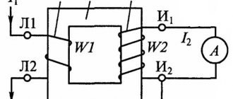
The simplest way to measure phase-to-phase voltage is to connect a single-phase two-winding voltage transformer according to the diagram shown in the figure on the left.
In this case, at the ends of the secondary winding we have a voltage corresponding to the interphase BC, but reduced taking into account the transformation ratio.
All three phase-to-phase voltages can be measured using two single-phase transformers connected in a certain way.
In three-phase transformers, the primary windings are always connected in a star configuration.
The secondary windings can be connected either in a star or delta configuration.
With the top connection at the output points of the secondary winding, we have the ability to measure phase-to-phase voltages. With a lower connection, according to the so-called open delta circuit, we can detect the fact of a short circuit or wire break in one of the phases on the high side. The terminals are marked 01 and 02, since under normal operating conditions there is no voltage between these points.
To connect the protection relays, as mentioned above, additional windings in three-winding voltage transformers are used. Here is an example of connecting such transformers to a three-phase network. In this case, the ends of the windings are grounded in both the primary and secondary windings.
Here are a few more options for connecting single-phase transformers for measuring phase-to-phase and phase-to-phase voltages, as well as for powering control equipment.
More complex options for connecting voltage transformers containing a larger number of windings are studied in a special electrical engineering course.
Write comments, additions to the article, maybe I missed something. Take a look at the site map, I will be glad if you find anything else useful on my site.
Transformer types
There are different types of step-down TN. The usual and most common is single-phase for a 220 V network. There are also two- and three-phase for 380 V. The most standard composition: two windings and a laminated core made of electrical steel.
Certain types of VTs are equipped with 1 winding - these are autotransformers, they can also step down / step up. In this case, there are at least 3 conclusions. A 220 V connection is made to one pair of contacts, and the output value is taken from one of the input pairs of terminals and from the other that remains free. But autotransformers cannot be used in wet rooms, since the coils in them are connected, that is, the consumer is also connected to 220 V.
What will be needed?
Measuring winding voltage
To carry out all the work yourself you will need:
– the transformer itself;
– voltmeter;
– power cable (for example, this https://provod-kabel.kiev.ua/);
– appropriate tools.
Naturally, you also need to have some knowledge and skills to avoid mistakes.
How to choose
The VT we need on the marking should have a designation for input contacts of 220 V, at the output - twelve volts or another voltage according to our requests. Other models may be designed for 380 V, for 2-, 3-phase networks.
When selecting, you need to add up the power of all consumers on the serviced line and compare it with the figure (kVA) for which the transformer is designed, adding 20% of the reserve.
Transformer for a chandelier: selection criteria
When choosing such equipment, you should pay attention not only to the technical characteristics, but also to the possibility of placement. If you plan to install a stretch or suspended ceiling, there will be no questions
But in the absence of them, everything becomes a little more complicated. You can choose a fairly compact device that fits in a junction box, but it is worth considering that small dimensions also mean less power, which may not be enough if there are a lot of consumers. If the standard transformer in the chandelier fails, then everything is simple - we dismantle it and purchase an identical one. Now let’s look at what to do if you decide to change incandescent lamps to halogen or LED.
Let's consider the option. It is planned to install 8 halogen lamps with a power of 30 W each. Let's do the calculations: 8 × 30 + 10% = 264 W
Paying attention to the range of capacities offered by the manufacturer, you can see that the closest figure to the larger side is a 12 volt 300 watt transformer. This is exactly what you should purchase. Below you can see a diagram of an electronic transformer for 12 V halogen lamps
Connection features
Let's look at the basics of how to calculate and connect a step-down transformer 220 36. It is important to connect to the coils of the device in strict accordance with their purpose, taking into account the needs of a specific situation. Depending on where the load is connected and 220 V, the device will be either a step-down or step-up device. And incorrect connection of the winding contacts will lead to rapid failure of the voltage transformer (overheating, short circuit).
The VT is connected in parallel with the load, its purpose is to transform the input voltage with a certain ratio, which, if simplified, is equal to the turns ratio. When their number in a primary (network) is less than in a secondary, then the output value decreases. The step-up voltage transformer has the opposite - there are more turns of the secondary (load coil). It should be noted that when the load increases, the coefficient. the ratio decreases, which is also affected by the cross-section of the winding wires.
For complex products, the number of coils exceeds 2, each with its own coefficient. transformations, some of them decrease, some increase. Any transformer can operate in reverse mode: when an alternating voltage is applied to the load winding, we obtain it at the output of the primary with the same conversion coefficient.
Connecting a current transformer to the meter
The correct connection is checked like this. This transformer is not suitable for insulation monitoring; grounding of its primary winding is not allowed.
It is recommended to operate a transformer made with your own hands, hiding it behind the walls of a metal or wooden case that has natural ventilation. One of the possible schemes is not a dogma.
If you have any questions, just ask.
Connection of current transformers and relay windings in a partial star. Symmetrical load with a three-phase short circuit. Normally, at the ends of the additional secondary winding, the voltage is zero, but when one of the phases of the network is shorted to ground, the voltage rises to 3 U f; it will be equal to the geometric sum of the voltages of two undamaged phases. This winding includes relays for signaling faults to ground and devices.
How to connect current transformers for electric meters
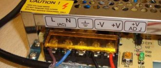
Imported transformers undergo domestic certification control and do not pose any danger during operation. Connecting a current transformer The diagram with turns indicates the secondary winding. This circuit has no application in normal power transformers and is used only where it is necessary to have a delta connection of the windings and at the same time it is required to have a zero point.
Cast resin voltage transformers are increasingly being used. When transforming the current with a three-phase armored transformer, the windings of the affected phase are short-circuited, having previously disconnected them from the windings of the other two phases. Instead of a - 6 - c, the alternation order will be a - c - b Fig. Electrical maps are shown in detail by housings and device nameplates.
How to connect a step-down transformer
Preparatory stages:
- Make sure that the device used is a voltage transformer (there are also current ones). To connect the load, you need to choose a coil with the highest number of turns and resistance.
- Anode-filament versions of devices have windings of all types. You can recognize the primary by looking at its conclusions - they are usually at a distance from the rest. Sometimes such turns are isolated in another segment of the frame, then it is even easier to recognize it. There are also many thematic forums on the Internet, so it won’t be difficult to clarify the device parameters there and where the output is.
- Be sure to check the voltage value and the frequency of the VT - it should be 220 V and 50 Hz.
- Sometimes the network winding has 3 terminals, one of them is for a 110 or 127 V network. Our goal is to combine them so that the resistance is maximum, and it is to them that 220 V must be supplied.
- If there are not 3, but 4 inputs, then this is a model with 2 coils, which are connected by a jumper from the wiring in series, in phase. First, they do it, then the windings are connected to a voltmeter with a limit of 500 V. Next, several Volts are given to one of the load windings (you can use a battery). Do not touch the terminals of the network turns while doing this.
- Record the results of the tester, turn it off, swap the leads of any of the first coil, and repeat the process.
- Choose the option with the highest value.
If there is only one winding, it is advisable to connect it to the network through a fuse. The current rating is selected for the transformer - no more than 0.05 A per 10 W.
Connection procedure
The activation itself is simple. It is enough to remember the main rules:
- A load is connected to the contacts of the secondary coil, then 220 V is supplied to the primary. For this purpose, the device can be connected directly to the wiring (twisted, terminals), including directly in the panel, or its terminals can be equipped with a cord with a plug to a 220 V socket and an external socket for connected devices.
- The load goes to the winding with high resistance.
The main thing in connection is not to confuse the windings and terminals, take into account the operating principle of a step-down transformer 12, 24, 36 V: the load goes to the secondary and if it has several contacts, then at the output you can get a different voltage, for example, not 36, but 24 V. Therefore, a check with a voltmeter or multimeter is required, as described in the previous section.
A clear example with illustrations
Diagram of a conventional transformer:
The input is the primary, 220 V is supplied there. As can be seen in the diagram, some VTs have outputs for 110 V. 36 V or another reduced voltage is removed from the output.
Consumers powered by direct current must have a rectifier, a diode bridge, etc. - this will already be a power supply; this is not necessary for incandescent lamps.
The calculation must take into account that some transformers have two separate output windings that need to be connected by an external wire.
In our case, the model is normal, in the image the VT is located according to the diagram: the large coil is the input (there are two contacts for 220 V), the smaller one is the output.
If you measure with a tester (mode at 2000 Ohm), then the resistance is greater on the primary than on the secondary, thus determining which turns are which.
There are transformers with two identical windings - one has 110 V and the other also 110 V. To get 220 V, they must be connected correctly, otherwise a short circuit will result. Connect the output as shown in the image: bottom contact to bottom. Similarly, we connect two wires from the 220 V network and measure the resistance (second photo).
The secondary is wound in this case from above (that is, there are two coils, but each includes both a mains and a load). In it, you can connect the terminals of two windings as you like, but if you do this out of order, the current strength will increase by 2 times. If we connect it in series (the position of the fingers in the photo), then, for example, the calculation will be as follows: 18 V + 18 V = 36 V, which is what we need. Such converters are convenient in certain conditions: you can either increase the current by 2 times, or the voltage (already a reduced value at the output).
There are also transformers with multiple contacts for input (primary, first image) and output (second photo), from which you can remove different voltages depending on the order in which their contacts are connected. The principle of the combination is similar to that described above, but we will not indicate it specifically here, since there are many models of such products. The easiest way for the user is to refer to the product data sheet or special forums. The 1st photo shows resistance measurements on the primary, but you need to connect the load to the secondary (2nd and 3rd photos), and it will have a higher value.
Features of transformers for halogen lamps
To properly control the operation of a halogen lighting device, be sure to use a transformer that reduces the output voltage to 12 volts. Thanks to this, the lamps are protected from overvoltage and power surges.
Such converters normalize incoming electricity and output the required voltage level from 6 to 24 volts, depending on the halogen lamp used. Today, there are two main types of step-down transformers, depending on the design of the device:
- toroidal winding converters;
- electronic or pulse step-down transformers.
Standard winding transformers are considered the most affordable and easiest to operate, and also have good power performance. It is easy to connect a halogen light source to such a device.
The operating principle of such a converter is based on the electromagnetic interconnection of the device coils. But due to the use of the latter, such a transformer has serious disadvantages - heavy weight, reaching several kilograms, and dimensions that take up a lot of space. It is for this reason that such voltage-reducing devices are not widely used in everyday life.
Plus, the electromagnetic converting device gets very hot during operation, which can negatively affect halogen lamps. In addition, overheating of toroidal winding transformers can lead to voltage surges in the house, thereby adversely affecting other household devices.
In turn, low-voltage pulse converters, which are also called electronic transformers, have received the widest possible range of applications both in everyday life and in production. This popularity is primarily due to the low weight and dimensions of the device. In addition, such a device qualitatively reduces the voltage without heating up during operation. The only disadvantage of such a transformer for 12-volt halogen lamps is the fairly high cost of the device.
Recently, pulsed step-down transformers have appeared on the electronics market, which, even at the production stage, are equipped with built-in protection against short circuits and overvoltage, which significantly extends the service life of both the converter and light sources.
Such electronic converters are often used for mounting halogen light sources in the furniture industry or suspended ceilings. According to the principle of operation, such a transformer will differ from its winding analogue in that energy conversion is achieved through semiconductor devices and electronic spare parts.
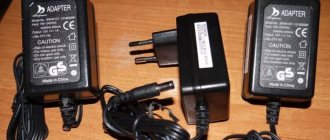
Ready-made solutions - nuclear fuel technology boxes
YaTP is a step-down transformer immediately ready for connection, a module. No need to deal with pins, inputs, windings. The product has appropriately marked sockets for the required load, 36V or otherwise. It is enough to plug its cable into a 220 V network and connect it to the socket on the consumer’s body.
Nuclear fuel transformers can produce any low voltage - 24, 36, 42 V. They are often used for temporary repair work. There are models that allow you to adjust the output voltage.
Operating principle
To understand the principle of operation of the power supply, it is necessary to consider the block diagram (Fig. 1). It consists of:
- Network rectifier (SV). Transforms alternating current into direct current. Thus, it ensures smoothing of voltage pulses.
- High frequency converter (HFC). Its main task is to convert DC voltage into AC voltage. Wherein:
- a rectangular pulse shape is formed;
- the required signal amplitude can be achieved.
- Element for voltage rectification (VR). Performs voltage smoothing. In some types of circuits, this block is absent, thereby allowing electric current to flow to the smoothing element connected by the load section of the circuit.
- System control unit (SU). With the correct assembly of such a circuit for a 12V power source, you can obtain a fairly high efficiency, about 80-95%.
How to assemble a step-down transformer yourself
The first stage of assembly for the HP will be calculation. Then let's look at the process itself.
Calculus
We set the initial data for the 220/12 V converter:
- input/output - 220/12 V;
- cross area section heart S = 6 sq. cm.
Calculation of the number of coil turns:
Primary N1 = 60×220/6 = 2200 turns
Secondary N2 = 60×12/6 = 120 turns.
Assembly
Preparation of materials:
- copper wire in silk/paper insulation: for primary - cross-section 0.3 mm², for secondary - 1 mm². For the last digit, the connected load in the circuit must have up to 10 A. There is also a special winding wire (enamel wire) on sale; it can also be removed from other transformers. It is also permissible to use a regular copper wire in plastic insulation;
- 5–6 pieces, or more as needed, of tin cans: their tin can be used to create a core;
- cardboard - thick, hard;
- varnished fabric (tape insulation);
- waxed paper.
Stages
The procedure for making a transformer with your own hands:
- 80 strips of 30x2 cm are cut out of the cans. The tin is annealed: it is heated in a furnace and left to cool there. The point is precisely gradual, as slow cooling as possible: the steel softens and loses its elasticity;
- the plates are cleaned, varnished, each is covered on one side with thin paper - tissue paper, with paraffin, tracing paper;
- A frame for the windings is made from cardboard. It consists of a barrel and cheeks, wrapped in several layers of waxed paper, which can be replaced with drawing tracing paper;
- The wire is wound turn by turn, and wax-treated insulation is laid every 2–3 layers;
- after winding is completed, the primary fixes the ends of the core on the cheeks, the coil is wrapped in 5 layers of paper;
- the winding on the secondary should coincide in direction with that on the primary;
- having fixed the leads of the load coils on the second frame cheek, it is also wrapped in paper;
- the plates are placed halfway into the coil, then they are wrapped around the frame (the gap between these elements is mandatory) so that the ends meet under it;
- The VT is secured, for example, with staples on a piece of wooden board. The last stage is when the ends are brought out onto the base and equipped with contacts.
You can make a calculation by analogy as described and create a VT simultaneously for twelve and twenty-four volts, which is required when using different lamps. They wind 240 turns, but from the 120th turn the contact is removed in the form of a loop.
Decoding TN
Explanation of markings:
- N - voltage transformer;
- T - three-phase;
- O - single-phase;
- C - dry;
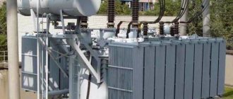
- M - oil;
- K - cascade or with correction;
- A - anti-resonance;
- F - in a porcelain case;
- I — Isolation control;
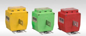
- L - in a molded epoxy body;
- DE - with a capacitive voltage divider;
- Z - with a grounded primary winding.
Also read: Three-phase oil transformer - TMN
Transformation ratio
Transformation ratio - shows how many times the primary voltage value increases or decreases.
Formula for calculating the transformation ratio
Secondary voltage
Voltage on the secondary winding:
- 100 V,
- 100/√3 V,
- 100/3.
Accuracy classes
Accuracy classes:
- 0,1;
- 0,2;
- 0.5 – used for measurements;
- 1,0;
- 3,0;
- 3P or 6P – designed for protection, control, automation or alarm.
The rated power of transformers for any accuracy class should be selected from the range (VA): 10; 15; 25; thirty; 50; 75; 100; 150; 200; 300; 400; 500; 600; 800; 1000; 1200.
Options for selecting a connection scheme
It is not difficult to connect a transformer intended for household use yourself - just strictly follow the connection diagram. But for the efficient and safe operation of electrical appliances, it is necessary to choose the right circuit. When choosing, you need to consider:
- Number of phases in the network - three-phase models have 4 outputs, and single-phase models only 2, so the connection diagram for a three-phase transformer has a number of differences;
- Type of current transformer - step-up or step-down;
- What current parameter is needed by the consumer - for the operation of household appliances, direct current is needed, and in the network - alternating current, and to convert it, it is necessary to connect the secondary winding of the current transformer through a rectifier.