Gas protection of transformers, operating principle of a gas relay
Gas protection for transformers is the most sensitive and versatile protection against internal damage. It is installed on oil-cooled transformers that have an oil conservator.
The principle of operation of gas protection is based on the fact that any damage in the transformer, including increased heating of the oil, leads to chemical decomposition of the transformer oil, as well as organic winding insulation materials, resulting in the release of gas inside the transformer.
This gas affects special gas protection devices, which give a warning signal or shut down the transformer.
Gas protection responds to damage such as an interturn short circuit in the transformer windings, to which differential and overcurrent protection does not respond; since in such cases the magnitude of the circuit current is insufficient to trigger the protection.
The nature of the damage in the transformer and the size of the damage affect the intensity of gas formation. If the damage develops slowly, which corresponds to slow gas formation, then the protection gives a warning signal, but does not turn off the transformer.
Intense and even violent gas formation, indicating a short circuit, creates a signal in the gas protection system of such a magnitude that, in addition to warning, causes the shutdown of the faulty transformer.
Gas protection for transformers also triggers a warning signal when the oil level in the tank drops.
Action of transformer gas protection
It is worth saying that gas protection has become widespread due to the special sensitivity of this system - it responds well to any internal damage that occurs in the object.
If there is any malfunction inside the unit, either an electric arc will form or the parts will heat up, and this will lead to severe decomposition of the oil and insulating materials, which in turn causes the formation of gases. Since volatile gases are much lighter than oil, they will rise into the expansion tank located at the very top of the transformer. If gas formation is too intense, the pressure of this substance will begin to move the oil, which will begin to move towards the conservator through the casing.
It follows from this that the gas protection of the transformer reacts to the intense formation of gases and the movement of oil inside the object, since in total these two actions signal that a breakdown has occurred inside the unit.
Gas relay - types, internal structure and design
There are three main types of gas relay:
The most common are gas float relays.
The relay body is a cast vessel made of aluminum alloy or cast iron, coated with a protective paint and varnish material with two floats. There are also single-float relays with flange or threaded connection. The relay vessel is embedded in a cut in an inclined pipeline designed to connect the transformer and expansion tanks.
Fig No. 1. Gas relay in transformer design
Gas relay elements
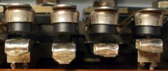
Let us repeat that the gas protection of the transformer is carried out through a relay. In other words, the principle of protection is based on the operation of this device. One of the fundamental elements of protection are flat-bottomed aluminum cups, which carry out a rotational movement in time with movable-type contacts around the axis of the cup.
These wires can become connected to the non-moving ones if the cups begin to fall. And during proper operation (when the oil volume in the relay housing is at an acceptable level), these basic protection elements are held in a certain position in which they do not close any of the contacts.
When the oil level in the casing drops, the cups also begin to fall along with the contacts, which close with other, stationary ones. Moreover, in case of minor damage, only the upper cup will lower, and the closure of its contacts will lead to the fact that the gas protection device of the transformer will only give a signal of a breakdown.
If the intensity of gas formation is high, then the flow of oil and gas will also affect the blade, which, when the contacts are closed together with the lowered cup, will cause a shutdown of the operating transformer.
During normal operation of the unit, the oil speed inside has values of 0.6/0.9/1.2 m/s. This indicator depends on the quality of cooling of the object. When a problem occurs, the response speed of the transformer gas protection takes from 0.05 s to 0.5 s. It can be added that on the territory of the Russian Federation, the gas relay with two spherical plastic floats BF80/Q is most widespread.
Gas relay
This type of protection in a transformer is represented by a mechanical relay, which is supplemented by two pairs of contacts. It is worth noting that the intensity of gas formation inside the transformer will directly depend on the degree and nature of the damage that caused this gas formation.
It is thanks to this that it is possible to create such gas protection for a transformer that will be able to determine the degree and nature of damage and, depending on the data received, send a signal or immediately turn off the unit. The main protection element in such devices is a KSG class gas relay. Its installation is carried out in the oil pipeline, which is located between the tank and the conservator.
Gas protection of transformers, principle of operation
The operation of the float mechanism is based on the principle of hydromechanics. Two mercury relay contacts are attached to the floats; they control the auxiliary current circuits. The float located on top has contacts connected to the signal circuit. The lower contacts located on the lower, second float are included in the transformer shutdown circuit.
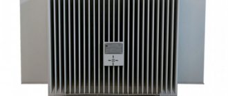
Fig No. 2. Float type gas relay
If the transformer has damage inside the housing, as a result of which gases are formed, like decomposition products of transformer oil, they will rise to the oil conservator and enter the gas relay.
Gas or air collects in the upper part of the relay, the transformer oil filling the gas relay vessel will be displaced, the upper float will lower, and the contacts will close, triggering a “signal.” The sound alarm sounds and the control blinker falls out at the substation.
The subsequent further decrease in the level of transformer oil in the tank causes the lower float to lower, and the lower contacts close, triggering the transformer shutdown.
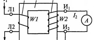
Fig No. 3. Schematic diagram of switching on a gas relay
Rapid gas formation causes oil to flow from the transformer tank into the expander, as a result of which the lower float turns the plate, it overturns, causing the transformer to turn off.
The relay is activated when the oil flow rate through the pipe is 50 cm/sec. The sensitivity of the relay to the oil flow rate is adjustable; for this, the adjusting weight on the graduated plate is set to the appropriate value. The relay is adjustable to operate at any oil movement speed from 50 to 150 cm/sec.
The operation of the relay can be monitored through the viewing window on which the level scale is applied. In the upper window, you can see how much oil is displaced in cm3, the lower inspection window shows the oil level above the upper edge of the throttle washer outlet in centimeters.
On the relay body, on its cover and on the bottom, there are two special taps; with the help of the upper one, gas is taken out and released; through the lower one, oil is taken out and the relay vessel is emptied.
Paddle type gas relay
The principle of operation of gas protection, a paddle-type relay is identical to the operation of a float relay, the difference is that its main element consists of a float and a blade, they are connected to a mercury contact that triggers a shutdown.
Cup type gas relay
Cup-type relays are more advanced modern models used in gas protection of transformers; instead of a float, there is a cup in the housing that can rotate around its axis. When the oil level in the relay drops, the contact closes; when gas is formed rapidly, the blade rotates and the contacts are switched off.
Operation of transformer gas protection
If the temperature is too high anywhere inside the transformer, the oil will generate gas. The gases formed as a result of this will tend to enter the expansion tank of the device, and in order to penetrate there, they will pass through the body of the gas relay.
It is through this that gas protection of the transformer is carried out. If the gas pressure in the relay housing is too high, the oil level will inevitably begin to drop, which, in turn, causes the cups to tip over. At this moment the gas relay is activated.
RKTU-01
Relay RKTU-01 continuously monitors leakage current in DC, AC or rectified voltage circuits (including monitoring the insulation of gas protection circuits). If the current exceeds the set limit (which is set by the user using a DIP switch on the front panel of the case), a trip signal is issued. The RKTU-01 relay has a wide range of response settings, thanks to which it can be used at various nominal operating voltages from 24 to 220 V.
If the gas relay contact closes, a current flows in the RKTU-01 input circuit, determined by the load of the gas protection circuit and obviously exceeding the fixed blocking setting.
Power transformers
In power transformers, in addition to the presence of a gas relay, which responds to gas formation and movement of oil towards the expander, there are also jet-type relays. The purpose of these relays is to protect the contactors of oil-filled transformer tap changers from damage that may occur due to too rapid flow of oil from the contactor tank into the conservator.
It is also worth mentioning that gas protection of power transformers is triggered even with the most minor damage, that is, even with low intensity of gas formation and at low oil speed. By the way, the electrical protection of the jet relay is not capable of detecting such minor violations.
Features of operation of gas protection of transformers
It is a mandatory requirement after each protection operation to inspect the transformer and check the condition of the relay. First of all, check the oil level in the conservator, make sure there are no leaks, check the integrity of the glass membrane installed on the exhaust pipe; in some cases, the membrane is made of oil-resistant rubber.
The presence or absence of gas is checked using a viewing window in the relay vessel, and the color and volume of the gas are determined. A gas sample is taken. The chemical composition of the gas should indicate the nature of the damage inside the housing, indicates the location of the fault, in the steel of the magnetic circuit or due to oil decomposition, the amount of gas helps determine the degree and nature of the damage.
For example, the presence of hydrogen oxide and dioxide indicates a fault in the insulation. The color of the gas is gray-white, which means that the electrical paper or oil barrier insulation made of impregnated cardboard is damaged; yellow gas indicates the destruction of wood; dark color indicates damage to the oil.
The gas flammability test occurs after taking a gas sample for chemical analysis. If the gas is burning, it means that putting the transformer into operation is strictly prohibited.
If there is air in the relay tank (gas does not burn), it is released through the valve in the relay housing, then an inspection is carried out; if there are no fallen protection trigger blinkers, the transformer is first turned on at idle, then, after the appropriate command, it is placed under load.
For gas protection of power transformers from 330 kV, if there is air in the relay, it is necessary to identify the cause of the air. Otherwise, there is a possibility that when the transformer is inserted, the insulation gaps may overlap.
There is a rule that says that all transformers with a power of 1 MW or more must be equipped with protection. To accomplish this task, gas protection of the transformer was chosen.
Furnace transformer protection
Features of operation and application of the Tesla resonant transformer
The operation of furnaces is associated with a sharp increase and decrease in current, therefore it is not recommended to use differential protection here, but only gas and thermal ones. The heating elements of such furnaces can operate on reduced voltage from 220–660 Volts. Most often, special electric furnace transformers are used here. Of course, we are talking about furnaces for melting metal, and not for cooking. In them, the melting modes are changed by both the supply voltage and the magnitude of the arc current. Furnace transformers must be equipped with protection against overloads, as well as in the event of a short circuit. Overload protection is installed on the low side, and current transformers for instantaneous operation on the high side. In this case, the relay setting is adjusted in such a way that it does not turn off during normal operational short circuits, because they operate in this mode and during some short circuits, the shutdown should not occur, but only the raising of the electrodes.
In any case, in the end, I would like to note that the consequences of abnormal operating conditions of the transformer, and therefore the cost of subsequent repairs, depend on the settings and correct operation.
Protection of power transformers, general information
As is known, power transformers (hereinafter referred to as ST
) are the most critical and expensive elements in the circuits of any electrical substations, therefore it is extremely necessary to competently approach the organization of their protection. Only this approach allows us to completely eliminate the possibility of damage from all types of short circuits and abnormal conditions.
Types of damage
. During operation of transformers, the following types of damage may occur:
- 3- and 2-phase short circuits on the low-voltage side; - single-phase short circuits to the body on the high-voltage side; - interturn short circuits; - short phase-to-phase short circuits behind the transformer; - short single-phase short circuits behind the transformer.
Types of protection
.
To protect STs
with a power of more than 1 MVA from internal damage and various abnormal conditions, the following types are used today:
Longitudinal differential protection
, which protects against all types of short circuits, both in the windings and at their terminals. As a rule, it is installed on transformers with a capacity of 6.3 MVA and above. The coverage area is limited by the current transformers on the high and low sides of the transformer.
Current cut-off
(), which does not have a time delay, is capable of protecting the transformer from all short circuits on the power source side. It is used in cases where the transformer is not equipped with differential protection.
Gas protection
, which protects
the CT
from internal damage, which is accompanied by the release of gases from the transformer oil, and from a decrease in the operating oil level in the tank.
It is used primarily for transformers with a power greater than 1 MVA and equipped with expanders. For the dry type, special pressure gauge protection is installed.
Jet protection
, which is a type of gas and is installed to preserve that part of the transformer tank where the on-load tap-changer is located. Acts to shut down when the speed of oil movement through the pipe connecting the conservator to the tank exceeds more than 0.9 m/s.
Maximum current
(MTZ), capable of protecting against short circuits inside the tank and at its terminals, as well as against all external short circuits. In this case, in the event of damage to the busbars and outgoing feeders and failure of its own switches, the transformer is switched off by the input switches.
Zero sequence current protection
(TNZP), necessary for protection against short circuits in a low-voltage network that operates in a solidly grounded neutral mode.
Special reserve
Overcurrent protection, which protects against interphase short circuits in a low voltage network and comes into effect in the event of insensitivity of the main set of overcurrent protection. Overcurrent protection in one phase, protecting against overcurrents caused by overload.
Transformers with a power of 0.4 MVA or more are equipped with this protection, which can be overloaded when the second parallel operating station
.
Protection signaling single-phase faults
to the ground in the windings, at the terminals and on the 10 kV supply lines.
Features of modern devices
. Of all the above measures, the main ones are differential and gas, which, without a time delay, turn off the transformer from all sides, keeping it intact and safe.
At the same time, overload protection, considered auxiliary, acts on the signal when it reaches 115% of the rated load. In some cases, when distant substations are serviced by fire safety teams, this protection can also be introduced to disconnect the transformer.
The result of all the above types of protection is a reduction in repair time for damaged equipment and the rapid restoration of normal power supply to disconnected consumers.
Today, all developers of modern types of protection for ST
They are trying to equip them on the basis of microprocessor technology, which is completely devoid of the disadvantages of electromechanical relays (for example, freezing contacts).
At the same time, a gradual departure from mechanics makes it possible to increase the overall reliability of the entire electrical equipment of an electrical substation by an order of magnitude.
Division of transformer protection into main and backup
Any type of damage in a transformer poses a potential danger to both the integrity of the equipment and the reliability of the entire power system. Therefore, it is extremely important to competently set up the operation of protections at power plants, traction and transformer substations, local transformer substations and transformer substations. For this purpose, transformer protection is conventionally divided into two categories - main and backup.
Basic protection is a type of automation that is aimed at analyzing the internal state of the transformer (windings, hardware, additional equipment). This type covers both the device itself and adjacent buses, wires, etc.
Backup protection covers those disturbances that occur outside the transformer but can directly affect its conductors and internal components. These are all kinds of overloads, short circuits and overvoltages in lines, on adjacent devices, etc.
Rice. 2. Primary and backup protections
Benefits of protection
Among the main advantages of gas protection of a transformer are the following points:
In addition to the above, we can add that all transformers with a power of 1,000 kW or more are supplied with this type of protection. However, there is a small drawback, which is that gas protection does not react in any way to damage to the unit’s terminals, and therefore must be equipped with a second protection against internal problems. For example, in low-power transformers, overcurrent protection and current cut-offs became such a protection system.
Protection Features
It is important to note that gas protection is multifaceted in its operating principle. It reacts not only to the formation of gases, but also to the presence of atmospheric air in the transformer, to movement or shocks of oil inside the casing, as well as to mechanical damage that may occur due to vibration of the unit housing.
In order to avoid false triggering of gas protection and unnecessary shutdown of the transformer, the lower float of the gas relay is most often set so that it responds to oil speed in the range from 50 to 160 cm/s.
Source
Gas relays RGT-50 and RGT-80
Transformer protection is one of the most important tasks of automation systems in substations. Its failure can lead to emergencies and significant material losses, because a variety of consumers are connected to it. Moreover, according to regulatory documents, gas protection is required for most transformers at substations with a power of 400 kVA and above, as it is the most effective and universal at the moment. To fulfill this requirement, gas relays are used, the features of which we will consider below.
The principle of operation of a gas relay for protecting a transformer is based on monitoring gas pressure. The relay is placed in a special metal casing and cut into the transformer oil line between the tank and the conservator. In the event of a sharp increase in temperature, which can occur for various reasons (for example, due to a short circuit in the transformer windings or a “steel fire”), the transformer oil begins to decompose or the organic elements of the winding heat up, causing gas to form inside the transformer.
Heated gases tend to enter the device expander, passing through the relay body. If the heating is weak, the gas pressure will increase gradually and the relay will give a warning signal without turning off the transformer. But at high gas pressure, which indicates strong heating, which, as a rule, is associated with a short circuit, the relay turns off the transformer.
It should be noted that a gas relay for protecting a transformer is capable of responding not only to the gas pressure formed as a result of heating, but also to the presence of atmospheric air in the transformer, to movement or shocks of oil inside the casing, as well as to various mechanical damage that can arise from - for vibrations in the unit body during operation. However, modern gas relays provide protection mechanisms against false operation and transformer shutdown. It is not for nothing that gas relays are widely used to protect transformers of various powers. There are three main advantages.
The first is the simplicity of organizing this type of protection. The second is the high sensitivity of gas relays. They even react to an interturn short circuit in the transformer windings, which is not available for differential and overcurrent protection. And the third advantage is relatively high performance. If a short circuit occurs, the gas relay turns off the transformer in a matter of seconds. That is why the use of gas relays to protect transformers is enshrined in regulations.
Today, there are several manufacturers in the country that produce gas relays for protecting transformers. One of them is, which produces gas relays RGT-50 and RGT-80 (Fig. 1).
In the mid-1990s, these relays replaced the Buchholz gas relays, widely used in the Soviet Union, produced by the Magdeburg Electrical Engineering and Instrumentation Plant (GDR), and today they are no less common in Russia than their predecessors. Gas relays RGT-50 and RGT-80 are successfully used to protect oil-filled transformers, autotransformers and reactors with an expander from damage inside the tank. Their flow sections have a diameter of 50 and 80 mm, respectively, and are designed for oil flow rates of 0.65, 1.0 and 1.5 m/s.
Rice. 1. Relay RGT-80
One of the main elements of such relays are the control contact blocks - BKR1 and BKR2. The BKR2 block has two floats - upper and lower, on which permanent magnets are installed that control the reed switches. The upper (signal) contact system of the relay is activated when the oil level in the transformer tank drops by 100–250 cm³.
The lower (disconnecting) contact system operates before the oil level reaches the lower level of the flange inlet on the relay body. As already noted, gas relays RGT-50 and RGT-80 have proven themselves in operation and are well known to our consumers.
At the same time, other products for electrical networks and protection of electrical equipment from ECCO-Technology have no less potential, which we will briefly describe below. Review of ESSO-Technology products The company presents a wide range of modern low-voltage and high-voltage equipment: KRU 2-10, KM-1F and KRUN, K-59, TEMP, relay RKTU-01 and other equipment. Let's look at these solutions in more detail.
The microprocessor terminal for control and protection of connections TEMP is used to protect overhead and cable lines, sectional and input switches. This device has rich capabilities and performs many protection, automation, control, measurement, recording and alarm functions.
Domestic gas and jet relays
Gas relays of the RGT series and jet relays of the RST series are a domestic analogue of the Buchholz relays, which were widely used during the Soviet Union.
New relays have improved characteristics, are developed and produced in the Russian Federation and make it possible to update outdated instrumentation without any alterations. LLC "ESSO-Technology", Cheboksary
In the Soviet Union, starting from the 1930s, three main types of gas relays were consistently used, which generally had a similar principle of operation, but differed in some design features. At first, oil transformers with expanders were protected from explosion and fire using Soviet-made relays PG-22, PGZ-22, PG-54 and RGZ-61, then - RGChZ-66. The last to be installed on Soviet transformers were Buchholz relays, produced in the GDR by the Magdeburg Electrical Engineering and Instrumentation Plant (EGEM) and supplied to the USSR since 1970. They included two elements: the upper (signal) and the lower (disconnecting), which began to move when the oil was displaced by gas from the relay. The signal and shutdown elements were floats to which magnets were attached. When the oil was displaced from the relay, the magnets began to interact with the magnetic control contacts, closing the alarm circuit or overturning the pressure valve (flap).
Buchholz relays were installed in most energy enterprises, but by the mid-1990s the instrument fleet was already in need of updating, and then a concept was developed: to create products that would be almost identical to their Western counterparts, but at the same time would have better technical characteristics and would be produced in Russia.
This task was completed in 1995. With the support of RAO UES of Russia, two enterprises - OJSC Firm ORGRES, a large company operating in the electric power industry since 1933, and OJSC VNIIR - in accordance with TU3425-002-00113483-96, jointly created gas relays RGT-50 , RGT‑80 and inkjet relays RST‑25. Currently, the main partner of OJSC Firm ORGRES for the promotion and sale of these products is ESSO-Technology from Cheboksary.
Relay RGT and PCT
Gas relays of the RGT series (Fig. 1) are designed to protect oil-filled transformers, autotransformers and reactors with an expander from damage inside the tank. When damaged, the oil heats up, gas is released, the oil level drops, or it spills from the tank into the conservator. RGT‑50 is designed as an analogue of the BF‑50/10 and RZT‑50 relays. The initial samples of the RGT-80 relay are BF-80/Q, RZT-80 and RGChZ-66.
Rice. 1.
Gas relay RGT‑80
Relay types are set depending on the bore diameter and the oil flow rate setting. Thus, the flow sections of the RGT-50 and RGT-80 relays have a diameter of 50 and 80 mm, respectively, and are designed for an oil flow rate of 0.65; 1.0; 1.5 m/s.
One of the main elements of the gas relay is the control contact blocks (BKR1 and BKR2). The BKR2 block has two floats - upper and lower, on which permanent magnets are installed that control the reed switches. In the RGT‑50 and RGT‑80 relays, the upper (signal) contact system is activated when the oil level drops by 100–250 cm³. The lower (disconnecting) contact system operates before the oil level reaches the lower level of the flange inlet on the relay body. When the oil flow rate in the pipeline from the tank to the conservator exceeds the relay operating value, the pressure plate shut-off system is activated.
The jet relay RST‑25 (Fig. 2) protects oil-filled transformers and autotransformers from damage when oil spills from the switch tank into the conservator. The relay is an analogue of URF-25 and RZT-25.
Rice. 2.
Jet relay RST‑25
The flow section of the PCT‑25 has a diameter of 25 mm and is designed for an oil flow rate of 0.9; 1.2; 1.5; 2.0; 2.5 m/s.
The contact system of the PCT‑25 relay is activated only by oil flow.
The response speed of the RGT and PCT relays is 0.1 s.
The installation and connection dimensions of all of the listed relays allow them to be used to replace existing RZT-25, RZT-50, RZT-80, RGC3-66, BF 80/Q, BF 50/10 and URF 25/10 without any modifications .
Features and advantages of jet and gas relays RST‑25, RGT‑50 and RGT‑80: - they have more advanced float and contact systems than their “predecessors”; — provide the ability to implement two independent shutdown and two independent signal circuits; — allow you to change the settings for the oil flow rate; — allow you to replace contact systems in case of their malfunction without removing the relay from the transformer.
In 2004 (Cheboksary), in partnership with OJSC Firm ORGRES, began work on the promotion and sale of relays RST-25, RGT-50 and RGT-80. LLC "ESSO-Technology" is one of the enterprises of the Russian electrical industry, specializing in the production of modern low-voltage and high-voltage equipment. This company has always worked in the field of import substitution, and therefore the “Switch to Domestic” concept proclaimed by the government was met with approval and enthusiasm. ESSO-Technology LLC has a quality certificate ISO 9001-2008 (ISO 9001:2008), which is proof of building an effective and modern management system.
Instead of an afterword. Blitz interview with the executive director of ESSO-Technology LLC Nikolai Valerievich Myasnikov
ISUP: Are the RGT and PCT relays literally analogues of old products, or has their design undergone some changes or been improved?
N.V. Myasnikov:
Of course, the design has been changed for the better. Buchholz relays can rather be called the “progenitors” of new relays. The development of the RGT and RST series was carried out by both research staff of the Institute of Relay Manufacturing and specialists from ORGRES who worked in the energy networks of RAO UES of Russia, and they knew well what difficulties arise when operating Buchholz relays. The information they had was taken into account in order to make the RGT and PCT relays more modern devices. This is the first, and the second, you understand, materials and technologies change over time. Thanks to their improvement, it is often possible to achieve higher quality at the same or lower cost of the product.
ISUP: The article is devoted to the production of inkjet and gas relays.
What could you tell us about other areas of your company’s activities? N.V. Myasnikov:
Of course, our work is not limited to the production of relays. We have a fairly wide range of products, which can be found on the company website. The main activity of ECSO-Technology is the production and supply of products for the repair of high-voltage circuit breakers, oil transformers, disconnectors and other equipment located at substations. It must be said that the production of spare parts for the repair of old substations is a large and important job. There is currently a lot of equipment in use whose service life is running out. It must be maintained in working order while it is being replaced with new, more modern products. It is impossible to simply take and replace everything at the same time due to the fact that this involves very large financial costs. Not all operating organizations have such funds. But substations must be kept in working order. Therefore, spare parts are replaced, while simultaneously and gradually introducing more modern equipment.
ISUP: What allows you to stay ahead of the competition?
N.V. Myasnikov:
Of course, we have competitors. But we also have a wealth of experience, which gives great advantages when working with customers. We have been repeatedly contacted on the recommendations of our old clients, they contacted us because they were faced with a problem: either they could not find the necessary equipment, or they were not able to identify some old part to replace. They just don't know its name! And then they recommend us, and we solve all problems.
RKTU-01
Relay RKTU-01 continuously monitors leakage current in DC, AC or rectified voltage circuits (including monitoring the insulation of gas protection circuits). If the current exceeds the set limit (which is set by the user using a DIP switch on the front panel of the case), a trip signal is issued. The RKTU-01 relay has a wide range of response settings, thanks to which it can be used at various nominal operating voltages from 24 to 220 V.
If the gas relay contact closes, a current flows in the RKTU-01 input circuit, determined by the load of the gas protection circuit and obviously exceeding the fixed blocking setting.
KSO, KRU, UBPVD, KRUN
High-tech equipment for electrical networks includes the following devices:
KRUN type K-59 are designed for receiving and distributing electrical energy of alternating three-phase current of industrial frequency 50 and 60 Hz with voltage of 6 and 10 kV. KRUN type K-59 are used as distribution devices, including at transformer substations (including complete, or block, transformer substations).
In addition to these products, the product line of ESSO-Technology LLC includes:
In conclusion, we note that it has another interesting area of work: it is engaged in the production and supply of products for the repair of high-voltage circuit breakers, oil transformers, disconnectors and other equipment located at substations. This is a critical task, given that it is impossible to quickly modernize networks, and old equipment must be in working order while it is gradually replaced by new ones. ECSO-Technology has a quality certificate ISO 9001-2008 (ISO 9001:2008), which is proof of building an effective and modern management system.
Source: ESSO-Technology LLC, Cheboksary
Source
Gas protection of transformers
Gas protection for transformers is the most sensitive and versatile protection against internal damage. It is installed on oil-cooled transformers that have an oil conservator.
The principle of operation of gas protection is based on the fact that any damage in the transformer, including increased heating of the oil, leads to chemical decomposition of the transformer oil, as well as organic winding insulation materials, resulting in the release of gas inside the transformer.
This gas affects special gas protection devices, which give a warning signal or shut down the transformer.
Gas protection responds to damage such as an interturn short circuit in the transformer windings, to which differential and overcurrent protection does not respond; since in such cases the magnitude of the circuit current is insufficient to trigger the protection.
The nature of the damage in the transformer and the size of the damage affect the intensity of gas formation. If the damage develops slowly, which corresponds to slow gas formation, then the protection gives a warning signal, but does not turn off the transformer.
Intense and even violent gas formation, indicating a short circuit, creates a signal in the gas protection system of such a magnitude that, in addition to warning, causes the shutdown of the faulty transformer.
Gas protection for transformers also triggers a warning signal when the oil level in the tank drops.
Transformer protection
The direct purpose of a protective device for a high power transformer is to protect it from internal damage. These internal threats include the following:
- Turn faults in windings such as HV and LV.
- Transformer steel fire.
- Oil leakage from the transformer tank.
The principle of operation of transformer gas protection is based on the fact that the system controls the decomposition of transformer oil, which occurs due to the effect of very high temperatures on gases. An increase in temperature is a local problem that occurs due to a short circuit in the winding of the device being described or when a steel fire occurs. When this problem occurs, the place where the failure occurred will become very hot, causing the temperature of the gases to also increase.
Gas relay operating principle
Gas protection (GZ) is carried out using special gas relays. The gas relay is a metal casing embedded in the oil line between the transformer tank and the conservator. The relay is filled with oil.
gas relay transformer
The casing has a sight glass with a scale, which is used to determine the volume of gas accumulated in the relay. On the cover of the gas relay there is a tap for releasing air and taking a gas sample for analysis, and there are also contacts for connecting the cable.
The designs of gas relays differ in the principle of execution of the reacting elements in the form of:
Float relays gas relay
Float relays have two floats mounted on hinges inside the casing, which are hollow metal cylinders. The floats are equipped with mercury contacts connected by flexible wires to terminal clamps on the relay cover. The mercury contact is a glass bulb with two contacts soldered into its vertical part. The cones contain a small amount of mercury, which at a certain position of the cones closes contacts with each other, thereby creating a circuit through a relay. When the speed of gas and oil flows is about 0.5 m/s, the lower float located in the flow path overturns and its mercury contacts close in the shutdown circuit. Due to the fact that in the event of a short circuit (short circuit) violent gas formation immediately occurs in the transformer, the GZ produces a shutdown within a short time of 0.1-0.3 seconds. The disconnecting element also operates when the oil level in the relay housing is greatly reduced.
Rice. 9.4 Float gas relay, principle of operation
Paddle relay gas relay
The principle of operation of gas protection, a paddle-type relay is similar to the operation of a float-type relay, differs in that its main element consists of a float and a blade, they are connected to a mercury contact, which gives a shutdown command.
Rice. 9.5 Vane gas relay operating principle
Cup relays
Cup relays use open metal cups instead of floats and usually open contacts operating directly in oil instead of mercury contacts. It is normal for the relay body to be completely filled with oil, while the upper and lower cups are also filled with oil and are held in their original state by springs.
Cup gas relay
The most famous and widespread gas relay is the RGChZ-66 type, produced by the Zaporozhye Transformer Plant.
Currently, gas and jet transformer protection relays of the RGT50, RGT80, RST25 types, developed by ORGRES and VNIIR, are produced. These relays have advantages over older designs.
Gas protection of transformer on-load tap-changer on jet relay
The gas protection of the on-load tap-changer of the transformer is made on a jet relay and acts to turn off the transformer when there is an intensive movement of oil flow from the on-load tap-changer tank towards the conservator.
The on-load tap-changer contactors are located in a compartment separate from the transformer tank. Since the arc burns in the oil when switching contactors, the oil gradually decomposes, releasing gas and other components. This oil does not mix with the rest of the oil in the tank and does not degrade its quality. The on-load tap-changer tank is also connected to the expander (separate compartment) and a special relay, for example, type URF-25, is installed in the connecting pipe.
Jet relay URF 25, URF 25/10
This relay is called a jet relay and only operates when oil is released. Once activated, the jet relay remains in the actuated position and must be returned to its original position by pressing the button on the relay. The relay is also equipped with a test button, by pressing which you can turn off the transformer.
The jet relay URF 25/10 is installed in the pipeline between the step switch head and the expander. Installing a relay allows you to control the oil flow. If the oil flow speed exceeds the response threshold of the valve gate (0.9-4.0 m/s ±15%, depending on the valve gate), the switching contact is switched on and the transformer is switched off.
Gas protection of on-load tap-changer
The gas protection of the on-load tap-changer of the transformer is made on a jet relay and acts to turn off the transformer when there is an intensive movement of oil flow from the on-load tap-changer tank towards the conservator.
The on-load tap-changer contactors are located in a compartment separate from the transformer tank. Since the arc burns in the oil when switching contactors, the oil gradually decomposes, releasing gas and other components. This oil does not mix with the rest of the oil in the tank and does not degrade its quality. The on-load tap-changer tank is also connected to the expander (separate compartment) and a special relay, for example, type URF-25, is installed in the connecting pipe. This relay is called a jet relay and only operates when oil is released. Once activated, the jet relay remains in the actuated position and must be returned to its original position by pressing the button on the relay. The relay is also equipped with a test button, by pressing which you can turn off the transformer.
OVERCURRENT PROTECTION DURING EXTERNAL SCROLL (MAXIMUM CURRENT PROTECTION)
Maximum current protection (MCP) is a backup protection of the transformer, and serves to disconnect the transformer in the event of its damage and failure of the main protections, as well as in the event of a short circuit on the busbars or on connections extending from them, if the relay protection or switches of these elements fail to operate. According to the conditions of selectivity, the MTZ must have a time delay and, therefore, cannot be fast-acting. For this reason, as the main protection against damage in transformers, it is used only on low-power transformers.
Protection of two-winding step-down transformers.
The MTZ transformer circuit with one-sided supply is shown in Fig. 8.21. To include the transformer itself in the protection zone, the relay is installed on the power source side and must act to open switch Q1.
Current overcurrent relays are switched on CTs installed at switch
Q2
. In Fig. 8.21, and a diagram of a relay transformer is shown, made with two current relays KA1
and
KA2,
which, having been triggered, with a time delay, simultaneously act to turn off the switches
Q1
and
Q2.
In this case, in the case of external short circuits on the low voltage (LV) side of the transformer, opening switch
Q2
reserves the action of switch
Q1.
Often relay protection is performed with two time delays;
from the first t1
to turn off the switch
Q1
on the LV side, and from the second
t2 = t1+Δt
to turn off
Q2
on the HV side.
CTs installed at switch Q2.
Rice. 8.21 MTZ of a two-winding step-down transformer
a - diagram of current circuits with three CTs; b - diagram of current circuits with two CTs
In the case of an undisconnected external short circuit on the LV side, the overcurrent protection with a time delay tx
will turn off switch
Q1
, while the transformer will remain energized on the HV side.
In case of damage in the transformer and failure of its main high-speed relay protection, the time-delay MTZ will turn off switch Q2.
Current relays KA1
and
KA2
in the MTZ circuit of transformers with HV 110-220 kV are connected to CTs connected in a triangle (Fig. 8.17, a). This design of the overcurrent current circuits prevents its possible non-selective action during a short circuit to the ground: in a 110-220 kV network (in the case when the transformer neutral is grounded). The protection can operate for all types of phase-to-phase short circuits on both the HV and LV sides of a transformer with a Y/Δ winding connection diagram.
CURRENT CUTTING
Current cut-off is a simple fast-acting protection against damage in a transformer. The cut-off area is limited; it does not operate in case of turn faults and ground faults in a winding operating on a network with a low ground fault current. The cutoff is installed on the supply side of the transformer and is performed without a time delay.
On transformers in a network with a solidly grounded neutral, the cutoff is set in three phases, and in a network with an isolated neutral, in two.
In addition, the current cutoff must be adjusted to the inrush of the magnetizing current; however, the setting selected according to the first condition is, as a rule, larger.
The cutoff area includes the busbar, terminals and part of the transformer winding on the supply side. The cut-off, which is a protection against internal damage, must disconnect the transformer from all sides that have power sources. The advantage of cutoff is its simplicity and speed. Cut-off in combination with overcurrent protection and gas protection provides good protection for low power transformers. Thus, a transformer with a voltage of 35 kV and a power of up to 4 mW can be protected with one UZA-AT device, UZA-10 by installing it on the HV side of the transformer and connecting it to current transformers connected in a triangle.
OVERLOAD PROTECTION
Transformers can be overloaded for significant periods of time. Therefore, if operating personnel are present, the transformer overload protection acts on the signal. In its absence at the site, control of the transformer overload can be carried out by means of telemechanics. Overload protection at facilities without permanent duty personnel can act on unloading or shutdown (if it is impossible to eliminate the overload by other means). Overload protection according to the PUE is installed on transformers with a power of 0.4 mW or more.
To ensure overload protection of all transformer windings, the following placement of overload alarm devices should be used.
— On two-winding transformers — on either side.
- On three-winding transformers with windings of the same power - on the supply side (usually HV). On transformers with possible power supply from 2 sides - from all three sides.
— On transformers with windings of different power on all three sides.
Thus, in order to cover all possible modes and parameters of the transformer, it is advisable to install an overload alarm on all three sides of a three-winding transformer.
The response time of the overload protection, in order to avoid false signals, must exceed the time of operation of the protection and restoration of normal mode by the automatic action of reducing the starting load current to the rated one. The time delay generally accepted in a number of energy enterprises is 9 seconds. It is set the same on all signaling devices that do not have special time delay requirements.
PROTECTION OF ELECTRIC MOTORS
GENERAL INFORMATION
According to the electrical installation rules (PUE), the following relay protection devices must be installed on motors with voltages above 1000 V:
— protection against phase-to-phase short circuits;
— protection against earth faults;
— protection against double ground faults;
— overload protection.
Synchronous motors additionally require protection against asynchronous operation. The types of protection used for this purpose depend on the power of the electric motors: Current cutoff is used as protection against phase-to-phase short circuits for motor power up to 5000 kW. It can also be used for engines of higher power that do not have phase terminals on the neutral side of the engine. For motors of higher power, and also if the current cut-off for motors of lower power does not meet the sensitivity requirements, differential protection is applied, provided that these motors have terminals on the neutral side. As protection against ground faults with fault currents of more than 5 A for motors with a power of more than 2000 kW, and 10 A for motors of lower power, zero-sequence current protection is used, which acts on shutdown. On lines supplying motors to mobile machinery, ground fault protection, for electrical safety reasons, must act to disconnect regardless of the magnitude of the ground fault current. On transformer-motor units, ground fault protection acts on the signal. This protection is included in all of the devices listed below.
As protection against double ground faults, zero-sequence current protection is used, which acts on shutdown. It is used in cases where the earth fault protection has a time delay. Its use is mandatory if protection against phase-to-phase short circuits is carried out in two phases.
Overload protection is required for motors subject to overload for technological reasons or under particularly severe starting conditions. Overload protection in accordance with CIS standards can be performed with dependent or independent time delay. Overload protection can act on unloading the mechanism through technological circuits or a signal: - 1st stage and on shutdown - 2nd stage. The time delay for overload protection at a current equal to the starting current of the motor is longer than the time it takes to start it. As a rule, with this type of engine protection there is a significant thermal reserve - conventional engines can withstand at least two starts in a row in terms of temperature. This makes it possible to perform the action of such overload protection to unload the mechanism.
Thus, according to the PUE, motors with a power of less than 5000 kW can have current cut-off, current protection against ground faults, and overload protection. According to the PUE, overload protection should act on the signal, unloading mechanisms and, only as a last resort, on shutdown. In such a situation, a significant time delay is not required; it is only necessary to adjust to the time of self-start of the electric motor.
The asynchronous mode is accompanied by an overload of the motor, and overload protection reacts to it. Therefore, overload protection often simultaneously functions as protection against asynchronous mode. Simple current protections can trip and reset when current fluctuates. Therefore, overload protection in asynchronous mode must accumulate a time delay. This principle should be incorporated into overload protection. Just as before, two stages of overload protection can be used: the stage with a shorter time delay acts on resynchronization, and the one with a longer time delay acts on shutdown. Since it is not possible to distinguish between overload mode and asynchronous mode in this case, automatic resynchronization cannot be provided. If there are on-duty personnel at the site, they can detect this visually when the 1st alarm stage is triggered. Special protection against loss of excitation is available in excitation devices for large motors. It is advisable to use these devices for automatic resynchronization.
For motors operating in a unit with a step-down transformer, general protection can be provided if it satisfies the protection requirements of both the motor and the transformer. To facilitate self-starting conditions, as well as to prevent the supply of asynchronous voltage to excited synchronous motors or braked mechanisms, motors must be equipped with undervoltage protection. This protection can be either individual or group. In some cases, to speed up the supply of voltage to the buses, or to prevent the supply of voltage to the motors by external network automation, synchronous motors can be additionally equipped with underfrequency protection, since they are capable of maintaining the voltage in the network for a long time. Therefore, when using such a relay to protect the engine, there is no need to use special voltage relays for this purpose.
In addition to the listed protection functions required for engines, special protections for engines have additional functions, the use of which improves the operating conditions of the engine, thereby reducing the likelihood of damage and extending its service life. These include:
— protection against phase loss;
— limiting the number of starts;
— launch prohibition based on the time elapsed from the previous launch;
— protection of minimum current or power;
— protection against jamming or rotor braking.
Special motor protection devices can work not only with current and voltage, but also with temperature sensors.
High-power engines also have technological protections that can act to shut down engines when: the temperature of the engine, its bearings increases, bearing lubrication stops, or air circulation in the cooling system.