Connection diagram for chandelier with remote control
The main design element is the signal switching controller. Most often, this is a non-separable box that contains information about connecting LEDs - LED, or halogen lamps - H. On Chinese controllers, the information may be in hieroglyphs with poor duplication in English.
The block shows a channel connection diagram
Such devices may be designated “Wireless Switch” or “Control Switch,” which means a switch controlled by a remote control. The most popular models are Y-2E and Y-7E. If one of the models is found, then we can consider ourselves lucky with the controller in the chandelier. Model Y-7E is best suited for home luminaires controlled by remote control.
Its structure includes:
- Three control channels, two of which are 1000 W each, respectively, for halogens and LEDs for a chandelier, one is 200 W for fluorescent light sources;
- Switching system for input alternating voltage 240V;
- A receiver that provides capture of the control signal from the remote control at a distance of up to 8 m.
For your information! More powerful models can use three 1 kW channels.
The diagram for connecting different types of lamps to their channel is shown below.
At the input to the controller, a pair of blue and brown wires is used; this is the standard color for the input voltage circuit. If you have doubts about the correct connection of the ceiling wires to the microcontroller unit, you can additionally look for the INPUT or input sign.
Important! The antenna is connected separately; as a rule, it is a short piece of wire in a dense white braid. You can't touch him.
How to connect an LED chandelier
The very fact of using a universal controller in a lighting device simplifies the task, since the device paired with a remote control can be removed from the chandelier and used in any other lamp. In addition, it is possible to use a chandelier for one type of light source - halogen or LED, without compromising the design. You just need to guess which pair of contacts corresponds to the button on the remote control.
Block for LED chandelier without remote control
It’s another matter if the LED chandelier is connected using a monoblock that has only one pair of pins. As a rule, the input to the block is made with wires of any color. Since the controller is not grounded, there is not much difference where to solder the zero and phase. At the output of the Chinese there is a pair of colored wires without markings.
Advice! Even if the box is marked “+” and “-”, before connecting the wires going to the LED lamp, you must check the polarity with a multimeter.
In addition, before assembling and hanging the chandelier, you need to check how the remote control works and whether the unit heats up under load. Separate tests are carried out on the range of signals from the remote control.
How to connect a halogen chandelier with a remote control
The connection procedure is no different from the LED version. The only addition is the installation of a step-down transformer for the halogen lamp.
The appearance of the step-down transformer is shown in the photo.
The trance power should be greater than the total lamp consumption
The number of electronic converters is equal to the number of halogens; as a rule, one or two blocks are used for each group of lamps, depending on the power and connection diagram.
Pass-through light switch
To control the lamps from two places, they do not install simple switches; pass-through SWITCHES are used, so named according to the principle of operation. Below is a visual comparison of their circuits.
The switch simply breaks or shorts the phase conductor passing through it, de-energizing or lighting the lamps.
The switch is designed differently, inside it, with each key press, the phase conductor is connected to one or the other internal contact. In this case, the phase does not break, but only transfers to the adjacent contact - because of this, the device is also called a changeover switch. Read on to find out why it is needed and how it is used.
Connection diagram for an infrared heater via a mechanical thermostat
This, in my opinion, is the most optimal connection diagram for an infrared heater. You can use any - mechanical, electromechanical or digital (electronic).
When implemented, many of the most important disadvantages of previous methods are eliminated.
In this case, you will need to carry out the electrical wiring from the electrical panel to the installation site of the infrared heater in advance. An option with external installation is possible, for example, in a cable duct - but this method is less safe and often spoils the appearance of the room.
Electrical wiring is laid from the electrical panel or other source to the thermostat, and from there it goes to the heater.
The most difficult thing here is connecting the wires inside the regulator. As an example of the most affordable and widespread mechanical thermostat, I took the BALLU BMT-1 model. His example, the diagram below, shows how to correctly connect the conductors inside.
Most mechanical thermostats have similar installation patterns, you can see this in the example of the ZILON model, which we reviewed earlier. In addition, instead of mechanical ones, digital (electronic) sensors are often used; they have a greater number of operating modes, adjustment options and external appearance. An installation example of one of them is available HERE.
Main disadvantages
— Larger financial costs than previous schemes
For implementation, it is necessary to first carry out the electrical wiring, purchase additional electrical equipment, a thermostat and cable.
— The need for additional electrical work
The need for preliminary work on laying cables and installing regulators requires the involvement of appropriate electrical specialists. Or the knowledge and skills, and most importantly the time, to do this work with your own hands.
— Impossibility of installing several IR heaters or one powerful one
The thermostat contacts rarely allow the possibility of connecting to it a current greater than 10A, in rare cases 16A. Accordingly, the maximum total power of heaters should not exceed 2-3 kW.
Advantages of connecting an IR heater via a thermostat
— Possibility of automatic adjustment of room temperature
You get a fully automated heating system. Which itself maintains the temperature, turns on and off at the programmed time.
— Ease of management
You choose the installation location of the thermostat yourself and its location is not tied to the installation location of the heating elements.
— Completely safe hidden electrical wiring
Electrical wiring is done in advance. In this case, you can choose the correct cross-section of conductors, the type of their connection in junction boxes, etc. In this case, all conductors are hidden, significantly reducing the likelihood of cable damage.
- Appearance
Cables hidden behind the wall decoration and the ability to choose the appearance of control devices allow you to preserve the original appearance of the interior and even decorate it.
CONCLUSION: If we ignore the installation difficulties and additional costs for equipment and electrical wiring, this is an almost ideal option in terms of functionality for small rooms. Where one or two heaters are often enough, the total current consumption of which does not exceed 10-16A to maintain a comfortable temperature, there is no better way to think about it.
If you have the task of heating a large room using several electrical heating devices or energy-intensive, powerful models, the best option for you is to connect through a thermostat and contactor.
This is interesting: Connection diagram for a self-retaining relay for a gas boiler
Wiring for turning off lights from two places
From the logic of operation it is clear that cables with a larger number of cores are supplied to the places where the light is turned on than for the switch. The image below schematically shows standard electrical wiring for turning on the light from 2 places, using a junction box.
Since everything is switched in an electrical junction box, three-core cables are laid from the devices to it (in an apartment or private house this is VVGng-LS 3x1.5mm.sq.):
— Up to each switch mechanism
- To the lamp
— To the electrical panel or the nearest electrical box
A total of 4 cables are used. Be careful, if there are more than two controls, this rule does not work.
Ways to use semiconductors in chandelier lighting control
The use of transistors is becoming much more popular. Their performance is characterized by long-term operation and high switching frequency. Several controls are provided for review and selection. Meter based control
Counting pulses are the basis for lighting control. The first one is usually responsible for resetting the counter. Repeated – for serial connection of lamps.
Each new press of the switch activates a new pair or group of lamps. To reset the pulses from the counter, it is enough to pause for a third of a minute.
Shift register in control system
The principle is already contained in the name itself. The impulse, hitting the starting point C, is transmitted further along the chain to D and 1.
The incandescent lamp circuit is connected and operates on the same principle as in the example with a meter.
To search for breaks in a faulty electrical network, use special
devices for detecting hidden wiring
. As an alternative method, this can be done using a radio or smartphone.
You can calculate the level of room lighting by knowing the luminous flux of the lamps used.
What to look for when choosing a voltage stabilizer can be found here
Thyristor control system
Rectifier VD6-VD9 powers the entire control circuit. When the switch is turned to the “On” position, the first lamp in the EL3 circuit lights up.
Next, the capacitors charge and accumulate the high and low signal so that DD1 keeps the transistor and thyristor off. When the switch is turned to the "Off" position, the capacitor is recharged.
Microcontrolling a chandelier
The microprocessor is equipped with software. Thanks to this, the operating principle can be unique. After all, such a scheme may have additional built-in functionality in addition to conventional lighting. Nevertheless, the same scheme as in previous cases is taken as a basis.
The connection and control diagrams for the chandelier do not have such significant differences.
Even the electronic system remains true to the original principle.
But what really doesn’t add up is the quality and durability.
Relay connection system
The relay method has a significant drawback: the system wears out quickly. A maximum of several thousand times of use will lead to circuit failure. As you know, it is located in a decorative cap under the ceiling. It is unlikely that anyone will be inspired by the annual procedures of dismantling a chandelier “at the root.”
Let's get acquainted with the relay connection system. Its main elements:
- thermistor R1, R2;
- capacitor C1;
- relay K1;
- diode assembly.
When the lamp is turned on, the cold thermistor (R2) has a high resistance force. High voltage is applied to the relay, the contacts open and the first 3 lamps in the circuit light up. After 1-2 seconds, the thermistor heats up, which gives a constant but reduced resistance in the circuit.
Turning off the power for half a second will be enough to prevent the thermistor from cooling down and all contacts remaining closed. Now all 6 lamps are lit.
The system is somewhat undeveloped, but still has the right to life.
For the “Electroeffluvial chandelier” scheme
An electroeffluvial chandelier, an ionizer, is an emitter of negative air ions that can increase the saturation of the air in a home room with air ions. The design consists of a square base made of 2 mm wire and a mesh of 1 mm wire, at the nodes of which pointed needles of wire with a diameter of 0. 3 mm. Four conductors, soldered together, go from the corners to the center of the square. High voltage is applied to this point, and through the insulator the chandelier
suspended from the ceiling. The thyristor high-voltage converter consists of a step-down power transformer T1, a rectifier on VD1, a storage capacitor C1, a high-voltage transformer T2 and a thyristor control unit - III winding T1, R2, VD2. Details. Instead of the KU201L thyristor, you can use the KU202N. The use of triacs (for example, KU208) is unacceptable. Any small-sized transformer T1 from a tube radio (wound independently on a Ш19 core, set thickness 30 mm: I winding - 2120 turns of PEL-0.2 wire; II winding - 2120 turns of PEL-0.2; III winding - 66 turns of PEL-0 ,2). zu on KT707 circuit T2 - high-voltage coil from the electronic ignition unit of the Tral chainsaw or magneto. Can be made from a core and a high-voltage coil from a TV type CNT-35 (“Record-66”, “Rassvet”). Wind the primary winding yourself with PEL-0.51 wire in the amount of 200 turns. Instead of a high-voltage column VT-18/0.2, you can use 5GE600AF. Insulate high-voltage wires only with PVC tape. Before turning on the converter for the first time, you must connect a 220 V lamp in the gap at point A. If after switching on the lamp lights up, swap the terminals of winding III T1. If after this a high voltage appears, but the lamp continues to glow at least slightly, increase the resistance of resistor R2. There should be no odors when the air ionizer is operating - this is a sign of the appearance... See description of the diagram...
Using a counter
Another circuit is built on logical elements. The essence of the idea is that you apply pulses and logical units alternately appear at its output. They are used to turn on semiconductor switches such as transistors.
Switching of groups of lamps occurs when the switch is quickly switched (on/off), so clock pulses are received at the input of counter C and logical units appear at the output. Work algorithm:
- EL1 & EL
- EL1 & EL3 & EL
- EL1&EL2&EL3&EL
The counter is reset when a signal is applied to input R. To do this, turn off SA1 for 15 seconds.
- Counting pulses are generated by DD3.
- The first switching on, a logical zero is formed at the output of DD3, is held from C2.
- A short switch discharges the capacitor and a logical one appears at the output of DD3. Element DD2.1 switches on the rising edge at the counting input. And so on with each short-term opening of SA2.
Parallel connection
In most cases, a parallel circuit for connecting spotlights (lamps) is used. Even though a large number of wires are required. But the voltage is supplied to all lighting devices at the same level; if one burns out, one does not work, all the others work. Accordingly, no problems with finding the location of the breakdown.
Parallel connection diagram for spotlights
How to connect spotlights in parallel
There are two ways to connect in parallel:
- Ray. Each lighting fixture has a separate cable (two or three wires, depending on whether you have a ground connection or not).
- Trailed. The phase coming from the switch and the neutral from the panel go to the first lamp. A piece of cable goes from this lamp to the second one, and so on. As a result, four pieces of cable are connected to each lamp, except the last one.
Radial
The beam connection scheme is more reliable - if problems occur, then only this light bulb does not light up. There are two disadvantages. The first is high cable consumption. You can put up with it, since the wiring is done once and for a long time, and the reliability of such an implementation is high. The second disadvantage is that a large number of wires converge at one point. High-quality connection of them is not an easy task, but it can be solved.
You can connect a large number of wires using a conventional terminal block. In this case, a phase is supplied from one side and, using jumpers, it is distributed to the required number of contacts. On the opposite side, the wires going to the light bulbs are connected.
Methods for connecting wires in radial design
In almost the same way, you can use Vago terminal blocks for the corresponding number of contacts. You need to select a model for parallel connection. It is better if they are filled with a paste that prevents oxidation. This method is good - it’s easy to implement (strip the wires, insert them into the sockets and that’s it), but there are a lot of low-quality fakes, and the originals are expensive (and it’s not a fact that they will sell you the original). That's why many people prefer to use a regular terminal block. By the way, there are several types, but carbolite ones with a protective screen are considered more reliable (they are black in the picture above).
And the last acceptable method is to twist all the conductors with subsequent welding (soldering will not work here, since there are too many wires, it is very difficult to ensure reliable contact). The downside is that the connection is permanent. If something happens, you will have to remove the welded part, so you need a “strategic” supply of wires.
An example of a beam connection for spotlights
To reduce cable consumption with the radial connection method, a line is drawn from the switch to the middle of the ceiling, fixed there, and wires are routed from it to each lamp. If you need to make two groups, install a two-key (two-position) switch, draw a separate line from each key, then turn off the lamps according to the chosen circuit.
Daisy chain connection
Daisy chain connections are used when there are a lot of lamps and it is very expensive to run a separate line to each one. The problem with this method of implementation is that if there is a connection problem in one place, all others also become inoperative. But localization of the damage is simple: after a normally working lamp.
Actual implementation of parallel connection in a daisy chain method
In this case, you can also divide the lamps into two or more groups. In this case, you will need a switch with the appropriate number of keys. The connection diagram in this case does not look very complicated - just add one more branch.
How to connect spotlights to a double switch
Actually, the diagram is valid for both methods of implementing parallel connection. If necessary, you can make three groups. There are also such three-position switches. If you need four groups, you will have to install two two-position ones.
Ceiling chandeliers - varieties
According to the number of lampshades, there are:
- chandeliers with one shade or lampshade (single-arm);
- with two shades or lampshades (double-arm);
- three-arm (with three shades), etc.
Basically, the number of lampshades depends on the style of execution (classic, loft, modern, etc.) and design. Moreover, the more shades and lamps on a chandelier, the greater the lighting power and, as a rule, the greater power consumption of electricity. The larger the area a given lighting device can illuminate.
By type of control, chandeliers are divided:
- wired control (two or three wire connection, plus a grounding contact if the chandelier has a metal structure);
- wireless control (via radio or from a phone via Bluetooth);
- combined options.
If you haven't bought a chandelier yet, just plan to do so
In this case, it will be very important to determine what type of wiring is installed in your apartment or house. The choice of a chandelier with a suitable connection diagram and control option depends on this
12 connection diagram options
Below is a table to help you make this choice. It is enough to determine what type of wiring you have and what switch is installed. If you select the right chandelier, no major alterations or interventions will be required in your existing wiring diagram. With the exception of some options, where there is a “change required” mark. We will discuss these changes below when we take a closer look at connecting the chandeliers of these models.
To decide on the choice of chandelier and connection option
- You need to determine your wiring type (2, 3 or 4 wire). Just look at the ceiling and see how many wires you have coming out of the ceiling in the place where the chandelier is attached.
- Which switch is used to control the lighting (in table 1, 2-key or dimmer).
- We select from the table the desired functions that correspond to the option number of your electrical wiring.
- And next to it, in the column, we see which chandelier performs these tasks.
You need to pay attention!
If you have 3 wires coming out of the ceiling, then in this case your wiring may have 2 “scenarios”
The difference will be that according to one option, one “phase” will come from the switch to the chandelier, and in the other option there will be two – “L1” and “L2” (pay attention to the number of keys on your switch)
If your wiring has 4 wires, then you can use any type of chandeliers and any controls here.
About connecting the ground wire in the chandelier
In modern chandeliers with metal fittings, a yellow-green
colors. The grounding wire is designated by the Latin letters PE
.
If the apartment's electrical wiring is made with a grounding wire (it should be yellow-green
, but can be of any color), then it also needs to be connected to the terminal to which
the yellow-green
wire of the chandelier is connected.
In old houses, apartment electrical wiring is usually made without a grounding conductor. Old chandeliers or those with plastic fittings also do not have a grounding conductor. In such cases, the grounding conductor is not connected; it will not affect the performance of the chandelier, since it only performs a protective function.
In the photographs, the wires coming out of the ceiling and chandelier are shown in white, and this is no coincidence. There is no single international standard for the color marking of wires in the electrical network, and even more so in chandeliers. And in Russia, the color marking of electrical wires has changed since January 1, 2011. Only the PE ground wire is marked yellow-green in the specifications of all countries
color.
Attention! Before connecting the chandelier, to prevent electric shock, it is necessary to de-energize the electrical wiring. To do this, turn off the corresponding circuit breaker in the distribution panel and check the reliability of the shutdown using the phase indicator
Installation of chandeliers with remote control
A modern manufacturer of lighting equipment for household needs is trying to make its products universal. The decision is correct; a chandelier designed for several types of lamps will be purchased faster than a product designed only for halogens or LEDs. It is this pair of light sources that will be the optimal combination for a ceiling lamp. Halogen provides powerful and rich lighting at night, while LED ideally illuminates the apartment space in the evening.
The optimal combination is a halogen lamp and two LED backlights
If you remove the decorative trim of a chandelier designed to be controlled from a remote control, you will be able to see several parts and pairs of wires:
- Microblock with a receiver and a controller for switching signals received from the control panel. This is the main unit, the wiring from the halogen and LED lines of the chandelier is connected to it;
- A wiring system, a transformer, necessarily electronic, and a set of halogen lamps;
- LED lamp line power driver unit.
First of all, you need to understand the markings and designations
Of course, the chandelier must come with a remote control and a wiring diagram. Although for many Chinese lamps, information about connecting and calibrating the remote control can be written on a tiny sheet of paper pasted on the back of the decorative cover.
Important! The remote control system for controlling the lamp uses high-frequency radio waves, most often in the 27.1 MHz range allowed for household toys.
This means that if a chandelier of normal quality was purchased and installed, the remote control will allow you to control the lighting from almost anywhere in the apartment. In addition, you will no longer need to point the box in the direction of the chandelier, as many do out of habit developed over years of handling the TV or air conditioner remote control.
Features of connecting a Chinese chandelier
The electrical part of lamps produced in Southeast Asia is often characterized by:
- reduced cross-section of conductors;
- the use of unknown alloys instead of copper for the manufacture of conductors;
- low quality of insulation of wires and terminal terminals (inelasticity of the material, reduced thickness, reduced insulating properties).
The first two points can lead to excessive heating during operation and further deterioration of the quality of the insulation, its cracking and shedding. This can be avoided by periodically removing the chandelier and inspecting it, but it is unlikely that anyone will do this at home. Therefore, it is necessary to at least check the quality of the wire insulation before installation. To do this, you need to unscrew the incandescent lamps or turn off the power supplies for halogen and LED lamps and measure the resistance between each core and the housing. It must be endless. It’s even better to take measurements using a 250 or 500 volt megger. If the insulation resistance turns out to be low or zero, you must return the Chinese chandelier to the seller or replace the conductors yourself with better ones.
“Smart Home” Do it yourself - Controlling a chandelier using two wires
Controlling a chandelier via two wires...
As you know, in many houses there are only two wires to the switch, in this case it is possible to turn on the chandelier in the room only as a whole (let’s say six lamps), but I would like to turn on only three light bulbs, and when, say, you need more light, turn on three more. In this situation, you cannot do without a third wire for an additional switch. Or maybe you are not yet going to make repairs and ditch the walls for laying the third wire. There is a way out of this situation; you will only need one module designed specifically for this. It is built directly into the chandelier (you can see how the module is connected in the chandelier in the figure at the end of the page). This module is compatible with all types of electric lamps! This means you can use LED or energy-saving lamps. Everyone knows that: Dimmers are absolutely incompatible with economical fluorescent light bulbs, and yet there are more and more such lamps! In Europe they have simply decided to legally ban the use of incandescent lamps. Three types of firmware were written for this module (three modifications of this module). We will consider each modification separately.
1. Control of the chandelier via two wires, “Normally off”
This module with this firmware modification is best installed in a closet or hallway. We connect the module according to the diagram below. The diagram shows that: One light bulb (or part of the chandelier) is connected directly and turns on every time it is turned on. The second light bulb (or part of the chandelier) is switched on through the module. When you turn it on for the first time, only one light will light up. To turn on or turn off the additional lighting channel, you need to turn off the light with the switch and turn it on again within one second, the second lamp will light up. The lighting turns off in normal mode, as before. The peculiarity of this modification is that the additional channel always starts in the off state.
2. Control of the chandelier via two wires, “Normally on”
This module with this firmware modification is best installed, for example, in the kitchen. When you turn on the light, both lights (both channels) will light up, and if necessary, the light can be dimmed (by turning off the additional channel). We connect the module according to the diagram below. The diagram shows that: One light bulb (or part of the chandelier) is connected directly and turns on every time it is turned on. The second light bulb (or part of the chandelier) is switched on through the module. When turned on for the first time, both channels (main and additional via the module) will light up. To turn on or turn off the additional lighting channel, you need to turn off the light with the switch and, within one second, turn it on again, the second lamp will light up or turn off (depending on what position it was in before). The lighting turns off in normal mode, as before. The peculiarities of this modification are that the additional channel always starts when it is on.
3. Control of the chandelier via two wires “With memory mode”
This module with this firmware modification is the most convenient in my opinion. The last state of the additional channel (on/off) is recorded in the microcontroller, and the next time the light is turned on, the additional channel will restore its previous state. That is, it remembers each of its states. We connect the module according to the diagram below. The diagram shows that: One light bulb (or part of the chandelier) is connected directly and turns on every time it is turned on. The second light bulb (or part of the chandelier) is switched on through the module. To turn on or turn off the additional lighting channel, you need to turn off the light with the switch and, within one second, turn it on again, the second lamp will light up or turn off (depending on what position it was in before). The lighting turns off in normal mode, as before. The peculiarities of this modification are that the additional channel starts in the state in which you last left it. This version of the firmware uses a non-volatile flash memory cell, and if the power goes out, nothing will happen.
Specifications:
Control: From a standard switch Memory: Non-volatile (FLASH) Maximum switched current: 220V - 500 Watt Overall dimensions, LxWxH, mm: 30x30x18 Article number: UL2 Supports work with all types of lamps.
Price: Negotiable.
Upon purchase you will receive: Assembled module, instructions.
To enlarge the image, hover over it
smart-home.do.am
How to live without a chandelier?
In fact, chandeliers are present in the homes of the indigenous people of the country. They are usually hung in the dining room, above the dining table, and in the kitchen to make cooking convenient.
There is usually no chandelier in the living room, and for good reason. Americans believe that there is no need for an overhead light source in this room. Family members watch TV or read books in the living room, and spot lighting is enough for this.
Residents of the United States feel absolutely comfortable lighting hundreds of candles every evening and being content with a faint flicker. For a Russian person, this option is not suitable. This, of course, is good for a romantic meeting with a loved one and creates a special aura in the room, but it is not suitable for spending time in the evening after a hard day at work.
Americans are accustomed to this way of life and do not pay attention to the inconvenience. But in their home appliance stores, lamps and fixtures are selling like hot cakes. And the choice here is colossal, for every taste and budget.
Many Russians who have moved to another continent are surprised by such “wrong” habits of arranging apartments. For most Russians, a chandelier is not only a way to illuminate a room, but also a source of pride. During renovation, the most expensive and beautiful one is selected. Therefore, we, Russians, will never understand Americans on this issue.
Controlling a chandelier via two wires | Electrics and low voltage
When dealing with repairs and all sorts of finishing and alterations, not every craftsman is able to provide for all the nuances and “little things.” And renovation and finishing work does not always include a complex of major renovations.
This happens very often with light. More precisely - with electrical wiring. For example: they forgot to run an additional wire for the lighting of the living room, or: they changed the wallpaper in the bedroom, but did not scratch the walls so as not to “spread dirt”, but there is no “evening” lighting for the room at all! There are many similar situations, and the modern idea of comfort is already inextricably linked with the wide possibilities of lighting design, with various lighting options. So let's think, because there are no hopeless situations!
Let's start with the most common case. In old apartments, only two wires are connected to the central chandelier, that is, even simple lighting in “two modes” cannot be done. Hammer the ceiling? Hang several sconces on the walls? Not necessary. There are many different “schemes” for controlling a chandelier via two wires - very simple, of medium complexity of implementation and quite serious electronic devices. We will look at the simplest and easiest to repeat switching circuit.
The very principle of “two-position” lighting is very simple, it is enough to reduce the current on the lamps of a lamp or chandelier, and by connecting a diode of sufficient power to the circuit, it will not be difficult to implement two lighting modes.
Using a regular two-key switch, we can turn on our chandelier at “half” power (S1), or at full power (S1 and S2 together). Where is it easier?
But if we add another diode of the same type to our circuit, only turning it on “in the opposite direction,” then the light will turn on when you press any “full-intensity” key, and the second key will turn on the full lighting power again. An additional advantage of such a scheme is that by first turning on the lighting “at full intensity”, we heat up the llama filament, increasing its resistance, and when full voltage is applied, there is no sudden jump in current, as with the usual switching on of cold lamps. Does everyone remember that light bulbs usually burn out the moment they are turned on? So, our circuit will extend the life of incandescent lamps indefinitely!
However, the possibilities of the two-wire circuit are not exhausted. Just a couple of new elements in the circuit make it possible to turn on and off individual groups of lamps.
Quite simple? And the functionality of such a switch is quite at the level - by turning on one switch key, we supply “half” voltage to L1, L2, L3, and lamps L4 and L5 do not turn on at all, since the diode “rectifies” the supply voltage, and the capacitor does not “pass” constant current.
As you can see, you don’t need to be a great specialist or professionally involved in electrical engineering to turn on the light in various configurations, having only a two-wire line at your disposal. To simplify the task even further, the approximate ratio of the power of the connected light bulbs and the capacity of the “control” capacitors:
Of course, these figures are approximate, you can install capacitors with a capacity of ±1.2 µF, it is important that the operating voltage of these devices is NOT LESS than 250V, or better yet, let it be 400V. These are, for example, ceramic capacitors K73-11, but diodes should be selected based on the ratio - 500 W ? 2.5 A, that is, the forward rated current of the diodes must be at least 2.5 A for a 5-arm chandelier with 100 watt bulbs, and the maximum reverse voltage of the diodes must be at least 250 V
In practice, you can use KD202 diodes with letter
index Zh, K, M, R, or any diodes KD203, KD206.
For a chandelier of lower power (say, 3 bulbs of 75 Watt each), you can use a KD226 diode V, G, D, E with a direct transmission current of 1.7-2 A.
The diodes for the presented circuits are mounted directly into the switch body, or in the installation box, as follows: From Figure 4 it can be seen that the diodes are connected “towards” each other to the common terminal of the double switch, where voltage is usually supplied, and the “input” and “output” The circuits are on opposite connectors. Nothing complicated. But the capacitors will have to be “hidden” in the casing or body of the chandelier itself, where the power wires are connected.
I would like to hope that thanks to this material, there will be one less “hopeless” situation during repairs!
Power of one light bulb, W Capacitance of the capacitor in the circuit, uF 100 10 75 7.5 60 6.5 40 4.5
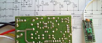
The process of repairing the chandelier control unit
The problem with the faulty controller was that more than one relay would not turn on. And sometimes one relay might not turn on. That is, if one more relay can be turned on, then the second and especially the third are no longer turned on.
To repair, you first need to make sure that the remote control is working (the batteries are normal, and when you press any button on the remote control, the indicator lights up), and supply power to the controller:
We connect the controller to carry out measurements and checks during the repair process
I connected the power through the Vago terminals, it is very convenient. I inserted both wires N (black) into the terminal block, although either one is enough. The fact is that I do not connect the load, and wire N, if it dangles, can short-circuit to the output phase wires. The presence of output voltages can be checked by connecting 3 load lamps. But you can do it simpler - check the presence/absence of phase at the outputs with a phase indicator.
For convenience, I recommend that you connect our device not through a Vago, but through a two-pole circuit breaker, so as not to plug it into a socket; it’s more convenient to turn it on/off. Denomination – the lower the better.
First of all, we check the supply voltage. We measure with a conventional multimeter, switched to constant voltage mode, on the electrolytic capacitor of filter C3. In relation to the common wire (minus the diode bridge and capacitors C3, C4, as is more convenient).
The voltage when the relays are turned off (almost no load, idle) on the filter capacitor is 11.2V; when any of the relays is turned on, it drops to 6V. At this voltage, even if the decoder gives a signal to open the transistor and it opens, the relay will still not turn on.
Naturally, suspicion immediately fell on the part of the electrical circuit responsible for power supply. Namely, to the limiting capacitor C2 in front of the diode bridge.
It says 155J. This means 15x10^5 picoFarads. And since there are a million picoFarads in 1 microFarad, this means that the capacitance of the capacitor is 1.5 μF. The voltage is clear, 250V.
If its capacitance has dropped, then it greatly limits the current of the diode bridge, and under load the voltage at the bridge output (and at the input, in the first place) drops significantly.
Another possible culprit for the drawdown is the electrolytic capacitor at the output of the diode bridge 470 uF 25V.
We change the 1.5 µF capacitor.
Now we measure the voltage at the output of the diode bridge in four operating modes:
- idle: 12.9V,
- switching on one relay: 12.2V,
- switching on two relays: 11.7V,
- switching on three relays: 10.5V.
Everything works fine!
Other malfunctions of chandelier controllers are below: