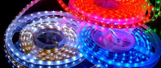
Addressable LED strips
The addressable LED strip became such a lighting device. The brightness and ratio of the basic colors, as in a conventional RGB lamp, are adjusted using the pulse-width modulation method, which is used for digital load control. The fundamental difference between an addressable device is that each light-emitting element is controlled separately (with a conventional tape, the entire segment of the web glows equally).
Possibilities of addressable LED strip.
The correct purchase of LED strip on AliExpress.
What else can be said about the cross-section of the wires? For example, a 2812 tape consumes about 60mA per diode. With a backlight length of 5 meters, the current will be 18 Amps!
According to all calculation tables, such a current requires wires with a cross section of 2.0-2.5 mm2. Even on the tape itself, copper tracks do not provide such a cross-section.
Therefore, if you want normal glow and brightness, even for standard 5-meter sections, always connect power at both ends.
In addition to the cross-section of the wires, the quality of the tracks themselves also plays an important role. Of course, the Chinese will tell you that they have the best products and no one has complained.
But how can you check this without buying the product? Elementary - request information on the weight of the tape. After that, compare identical models from different manufacturers.
For example, for a strip 5m long (60 LEDs per meter) with a weight of less than 100g, voltage drops begin after 1.5 meters!
This is explained by very thin copper tracks or low-quality copper in them.
Address tape device
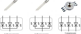
Addressable LEDs became the basis for the construction of such lighting devices. They contain the actual semiconductor light-emitting element and an individual PWM driver. Depending on the type of addressable element, the RGB LED can be located inside a common housing or be remote and connected to the driver pins. Separate LEDs or an RGB assembly can be used as a light emitter. The supply voltage may also vary. Comparative characteristics of common microcircuits used to control color LEDs are given in the table.
| PWM driver | U supply, V | LED connection | Note | Current consumption |
| WS2811 | 12-24 | External | Built-in 12 V voltage regulator. Fast and slow modes | Depending on the LEDs used |
| WS2812B | 5 | Built-in | LED form factor - 5050 | Up to 60 mA per element (at maximum brightness) |
| WS2813 | 5 | Built-in | LED form factor - 5050 | Up to 60 mA per element (at maximum brightness) |
| WS2815 | 12 | Built-in | LED form factor - 5050 | Up to 60 mA per element (at maximum brightness) |
| WS2818 | 12/24 | External | Control input voltage – up to 9 V. Additional control input | Depending on the LEDs used |
The current consumption of one meter of address tape is quite high, because power is spent not only on the glow of pn junctions, but also on switching losses of PWM drivers.
How to calculate the number of addresses for DMX 512 tape
DMX (RGB)
• 1 pixel = 3 DMX channels (RGBW) • 1 pixel = 4 DMX channels (RGBW)
By having different densities of LEDs on a strip and different lengths, you can multiply it all together and get different results.
For example:
• (8PL30) 30 RGB LEDs/m strip x 5 meter reel = 150 pixels (150 pixels x 3) = 450 channels • (8PL60) 60 RGB LEDs/m strip x 5 meter reel = 300 pixels (300 pixels x 3) = 900 channels • (8PL144) 144 RGB LEDs / m strip x 2 meters = 288 pixels (288 pixels x 3) = 864 channels • (8PX30) 30 RGBW LEDs / m strip 5 m = 150 pixels (150 pixels x 4) = 600 channels • (8PX60) 60 RGBW LEDs/m strip x 4 meter reel = 240 pixels (240 pixels x 4) = 960 channels
Convenient to remember:
• 170 pixels RGB = 510 channels DMX = 1 DMX universe • 128 pixels RGBW = 512 channels DMX = 1 DMX universe
Design of the lamp element
Each addressable LED contains a minimum number of pins:
- U power (VDD);
- common wire (GND);
- data input (DIN);
- data output (DOUT).
This allows elements with built-in emitters to be placed in 4-pin packages (WS2812B).
WS2812B pinout.
Microcircuits with external LED connections will require at least three more pins to connect LEDs. As a result, a standard package with 8 pins has one free leg, which developers can use for other needs.
WS2818 pinout with additional data output.
Thus, the designers of the WS2811 chip used a free output for the speed switch, and WS2818 - for a backup data input (BIN).
Where can I buy?
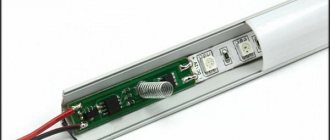
The photo below is of the WS2812B that I purchased for myself. Its length is 5 meters, and the LEDs are hidden behind waterproof silicone. That is, you can safely leave it where it may be rainy or even dusty.
In my opinion, this is the best type of LED strips. You can control the brightness and color of each LED individually, allowing you to create complex and very beautiful effects.
The LEDs in the WS2812B strip are connected to each other in series. In addition, each LED is equipped with its own chip, which allows you to control the strip via 1
-wired interface. This means that you can control all the LEDs on the strip using just one Arduino digital pin.
The photo below shows the chip that each LED is equipped with. In addition, each LED is RGB
-Light-emitting diode.
LED strips of this type are very flexible. They can even be cut to the desired length. In the picture below you can see that the tape consists of segments, and each segment consists of one RGB
-LED.
The incision must be made in a special place, which is marked with a black stripe.
There is a connector at each end of the strip. I decided to cut off the connectors and solder comb pins instead. This is more convenient if you want to connect the LED strip to an Arduino or breadboard.
Connecting elements
All elements located on the canvas are connected in parallel via power supply, and in series via the data bus. The control output of one microcircuit is connected to the input of another. The control signal from the controller is supplied to the leftmost DIN pin of the driver circuit.
Connection diagram of elements on the canvas.
It is better to power the LEDs and microcircuits from a separate unit, especially if the strip is powered by a voltage other than 5 V. The common wire of the controller and the voltage source must be connected.
Appearance of a piece of tape on the WS2812B.
Connection over 5 meters.
If you need to connect more than 5m of smart tape, then to ensure its uniform glow, you cannot simply increase the backlight sequentially. We are talking here primarily about nutrition!
When the number of pixels on the controller allows you to connect a large length, you can easily connect the DI and DO connectors together. But the power supply (5V or 12V) will still have to be pulled separately (in parallel).
There are controllers with additional wires for “extra” power in such a case.
Mistake #6
You cannot connect several pieces of tape in series and at the same time apply an initially higher voltage to them.
For example, take three pieces of ws2812b (5m+5m+5m) and apply 15 volts to them at the very beginning of the tape, counting on a consistent voltage drop.
In this case, you will have to install your own controller for each segment, and somehow guarantee the same consumption of the segments.
Mistake #7
The ribbon glows with a yellowish or red tint instead of white.
Most likely the issue here is an incorrectly selected wire cross-section. Always use a minimum of 1.5mm2.
Lack of color is the first sign of voltage sag. The shift to red is explained by the fact that blue and green colors on the 2812b chip require about 3.5V, but 2V is enough for red.
Therefore, when the voltage on the LEDs drops, the green and blue crystals turn off, and the red one remains on until the last one.
Glow control
The elements of the address tape are controlled via a serial bus. Typically, such buses are built using a two-wire circuit - a strobe line and a data line. There are such tapes, but they are less widespread. And the devices described are controlled using a single-wire circuit. This made it possible to simplify the canvas and reduce its cost. But this is paid for by the low noise immunity of the LED device. Drivers can interpret any induced interference with sufficient amplitude as data and light up unpredictably. Therefore, during installation, additional measures must be taken to protect against interference.
The control protocol contains 24-bit commands. Zero and one are encoded as pulses of the same frequency, but of different durations. Each element writes (“latches”) its command, after a pause of a certain duration, a command is transmitted to the next chip, and so on along the chain. After a pause of increased duration, all elements are reset and the next series of commands is transmitted. The disadvantage of this principle of constructing a control bus is that the failure of one microcircuit interrupts the transmission of commands further along the chain. The latest generation drivers (WS2818, etc.) have an additional input (BIN) that avoids this problem.
Software part
The code and libraries can be downloaded here.
SUP_v1.0Download
Unpack the archive, copy the libraries from the lib folder to the C:\Program Files (x86)\Arduino\libraries folder.
Then open the file SUP_V1.0.ino and see the settings:
Next, connect the Arduino to the computer and upload the code. After the “download complete” message, you can check the functionality of the device.
Short clicks on the button change the color of the ribbon according to the prescribed array of colors, long clicks increase or decrease the brightness one by one.
The brightness is adjustable for two modes, when the motion sensor is triggered and without it being triggered. Adjustment for each mode is made in the state of the sensor in which you want to adjust the brightness.
This was the home version of the backlight, and now I’ll show you the car version:
"Running Fire"
The so-called SPI tape, which in everyday life is called “running fire” because of the most common lighting effect that is built on it, deserves special consideration. The difference between such a tape and the types considered is that the data bus contains two lines - for data and for clock pulses. For such devices, you can purchase an industrially manufactured controller with a set of effects, including the aforementioned “running fire”. You can also control the glow from conventional PIC or AVR controllers (including Arduino). Their advantage is increased noise immunity, but the disadvantage is the need to use two controller outputs. This can be a limitation for building complex lighting systems. Also, such devices are characterized by a higher cost.
SPI tape with a two-wire control bus.
What else needs to be done
Look!!! The tape came in a reel, and when connecting it to the power supply, the power supply went into protection, most likely this was due to the fact that the contacts were connected to each other and there was a short circuit. Since the tape is open without insulation. As soon as I untwisted the tape, everything became normal, so pay attention, if the block goes into the protection, then remove it from the reel and everything will be fine.
If everything was done correctly, then everything will work perfectly.
To make the light more diffuse, I bought clear heat shrink tubing. I cut it into 2 cm pieces and crimped each LED into pieces. So the light became softer and more diffused. And besides, you can safely roll the tape into the spool and connect it without fear of shorting the contacts.
Also in these circuits you can use 12-volt power supplies, but connect them through a 5-volt voltage converter. Or use other types of tapes, but you need to look at the settings there, since they have a different LED operation scheme. And adjustments need to be made to the firmware. Happy holidays and a good new year!
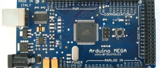
I also connected an Arduino Nano V 3.0 with the same firmware to another address tape that I used in the color music project. And it turned out to be a pretty good effect. And you can also make something out of it. For example, I glued it to the table and made the table illuminated, it also looks pretty good. Look at the video on YouTube at the bottom of the article.
Lamp connection diagram and typical errors
The connection circuit for multimedia devices has much in common with the circuit for conventional RGB lights. But there are also differences - in order to correctly connect an addressable LED strip to the controller, you need to keep a few points in mind.
- Due to the increased power consumption of the address tape, it cannot be powered from the Arduino board (if small segments are used, this is undesirable). In general, a separate source will be required to provide power supply (in some cases there may be one, but the power circuits for the LEDs and the controller must be made separately). But common wires (GND) of the power circuits and the Arduino board must be connected. Otherwise, the system will not work.
- Due to reduced noise immunity, the conductors connecting the controller output and the web input should be as short as possible. It is highly desirable that they are no longer than 10 cm. It would also be a good idea to connect a capacitor C to the power line with a voltage higher than the supply voltage of the tape and with a capacity of 1000 µF. The capacitor must be installed in close proximity to the tape, ideally on the contact pads.
- Tape sections can be connected in series. The DOUT output must be connected to the DIN input of the next piece. But with a total length exceeding 1 meter, a serial connection cannot be used - the conductors of the web power lines are not designed for high current. And in this case, it is necessary to use a parallel connection of segments.
- If you connect the controller output and the DIN input directly, if an emergency occurs in the luminaire, the controller output may fail. To avoid this, a resistor with a resistance of up to several hundred ohms must be placed in the wire gap.
Failure to follow these simple rules may result in the multimedia system not working or its components failing.
Wires and connectors
A digital tape at the end has at least not two, but three wires.
- V+ (5V or 12V)
- V-(GND)
- control wire
Two of them are normal power, and the third is responsible for the direction of the signal. Special connectors are soldered to the wires at the ends of the ready-to-use product:
- DI (Digital Input) or digital input at the beginning of the tape
- DO (Digital Output) digital output
If you have such connectors, you will not be able to connect the tape with the wrong side. The second DO end is required when increasing the length of the light structure.
Mistake #4
But without such connectors, the beginning and end of the tape can be confused.
In this case, nothing will burn or glow.
Mistake #5
The power cables from the controller are too long.
If you have a situation where the tape does not light up until you touch and run your hand over the power wires, then most likely they are too long and the control wire is subject to interference.
In this case, try twisting them into a pigtail. It helps in some situations.