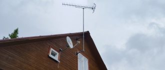
Input panel on the pole
So what do we have initially?
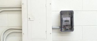
Local electricians installed a plastic box on a pole, which is better called a single-phase input switchgear (IDU) or metering panel, in which they mounted an AMS b1b-sa2sc meter and two machines - C63 before the meter, and C50 after it. Input cable – two-core, stranded aluminum with a cross-section of 16 mm2:
VRU. Aluminum cable entry on pole
An isolated overhead line (IOL) comes from a transformer, which is located more than a kilometer away. There is an assumption that the short-circuit current in the section will be relatively low. I wrote on my blog what this means and what conclusions can be drawn.
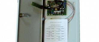
Closer photo of the internal structure of the shield:
Shield on a pole with input machines and a counter
Judging by the rating of the input machine, the allocated power is more than 13 kW, which is very good for rural areas. Next, the connection is made with rigid aluminum conductors with a cross-section of 10 mm2, and a 2x1.5 SHVVP wire with a length of more than 15 m is temporarily screwed in, which goes to the house under construction.
With such machines at the input, taking into account the fact that all electrical wiring will be done “from scratch,” it must be done with high quality, on a budget and safely. It is important that the scheme must take into account all the nuances that may emerge in the future, so as not to be remade later.
An input distribution device (IDU) is
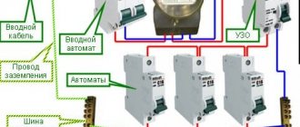
The copper bus N is intended for connecting the zero working conductors of the home network. In the input distribution device ASU, the PE and N buses are connected to each other, but according to certain rules. The protective grounding conductor is connected to the PE bus, from which wiring is carried out throughout the premises. Bus N must be secured to the ASU body through dielectric non-conducting insulators.
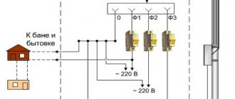
First input: 1 power supply line for apartments, 2 supply and group lighting lines for common building premises, stairs, corridors, lobbies, halls, technical undergrounds, attics, lighting of entrances to the house, number lamp, etc. The metering of the switchboard is determined by installing an electric meter in it.
The input circuit depends on the circuit of external supply lines, the number of floors of the building and reliability requirements, the presence of elevators and other power electrical receivers, the presence of built-in enterprises and institutions, and the magnitude of electrical loads. A characteristic feature of building an ASU circuit at home is the separate power supply of apartment loads and working lighting of common building premises from one input and power consumers from another. If we divide it in another place, in a house or in panels on a floor or apartment, we get a TN-CS system; X1..... In some cases, when it is appropriate due to the conditions of load distribution at the inputs, it may be possible to supply the tenants' lighting installations from the power input, but the possibility of connecting them is checked by calculation. The input circuit breaker is designed to protect the electrical wiring of the house from overload and ultra-high short circuit currents, as well as deliberate power outages for maintenance of the home network.
The phase wires go through the main three-phase circuit breaker to the meter. An example of calculating an ASU circuit
Structural electrical diagram of the site
First you need to decide what and where it will be:
In the ASU, electricity is distributed to three consumers -
- per home (main consumption), maximum power consumption - 7.5 kW, distance to the home distribution board (distribution board) - 15 m,
- to the summer kitchen (later there will be living quarters for guests) - 2.5 kW, distance to the control panel of the summer kitchen - 20 m,
- for outbuildings (workshop, shower, toilet), max. power – 2.5 kW, distance to the summer kitchen control panel – 20 m.
Block diagram of electrical equipment
All capacities are given taking into account a utilization factor of 0.7. This means that, theoretically, consumers can have the following maximum power:
- house – 10.7 kW,
- summer kitchen – 3.5 kW,
- outbuilding - 3.5 kW.
That is, up to 70% of all electrical appliances of each ASU consumer can operate for a long time at the same time. If the percentage (utilization rate) is higher - for example, relatives and guests have arrived, and a large feast is planned - then the time of simultaneous use of each of the consumers is limited to several minutes. After this, the corresponding AB can be “knocked out”.
Scheme of the ASU (input electrical panel)
Obviously, the ASU will have one input circuit breaker (AB), which is already installed, and three AVs, through which power is supplied to 3 consumers.
We select the cable cross-section and AB rating for
the house .
Now the AB is installed at 50 A, it will have to be removed. This relates to safety and costs - for 50A you need to install a thicker cable, this does not make sense. For a power consumption of 7.5 kW, the current is 7500/220 = 34 A. The cross-section of the copper core of the cable going to the house is chosen to be 6 mm2 . We select a machine with a rated current of 32 A (its time-current characteristic is such that at a current of 36 A it will turn off no earlier than after 1 hour)
For a summer kitchen and outbuildings (power 2.5 kW) you need cables with a core cross-section of 2.5 mm2 , protected by 16 A .
Next we solve the issue with grounding. It turned out to be not so simple. Two grounding systems suggest themselves:
TT – with a circuit (grounding electrode) not electrically connected to the PEN conductor or neutral coming from the street. The advantage of the system is that it is independent of the state of the street electrical network. There is no need to redo anything or connect anything additional. But the minus lies there too - if a voltage appears at the incoming neutral that is very different from the ground potential, it can do a lot of business. In addition, I recommend installing an SPD, because the Black Sea coast of the Caucasus, according to the map given in the PUE, is the most dangerous in terms of thunderstorm activity. And with a TT system, lightning protection will be cumbersome or ineffective.
TN-CS – grounding system with re-grounding and separation of the PEN conductor into the neutral wire (bus) N and protective PE. It takes a long time to explain, but such a system involves re-grounding, installing a main grounding bus (main grounding bus) and separating the PEN conductor BEFORE THE COUNTER. Otherwise, if the grounding is connected after the meter, it will be incorrect and unsafe. This is aggravated by the fact that the input is not a two-pole, but a single-pole AB.
You can read in detail, for example here – https://we.cs-cs.net/blog/506.html and https://cs-cs.net/vru-vvod-zazeml and https://zen.yandex.ru /media/yury_kharechko/kak-pravilno-vypolnit-zascitnye-provodniki-v-sistemah-tns-tncs-i-tt-5f9346b7a81c50318e18ec3e
Therefore, it was decided to install a protective grounding bus PE (GZSh) to the meter distribution block on a DIN rail RBDp-35 with a width of 43 mm. It has a central conductor, which passes through it through stripping the insulation, and can have a cross-section of up to 25 mm2, and 4 smaller wires - up to 6 mm2.
This block will play the role of a main shield, it will receive a PEN conductor from the street and a protective conductor from the grounding device (circuit) with a cross-section of 10 mm2. The protective conductor PE and the neutral conductor N (through the meter) will go from the GZSh (PE bus) to consumers.
I hope that the RBD-p with the PE bus will not be sealed (like the introductory AB). After all, the contacts need to be stretched, and it may be necessary to replace or add a cable. But if, nevertheless, the sealing of the RBDp-35 pass-through block is required by the energy supervision authorities, you will have to make a separate PE bus, which does not need sealing. And connect the protective wires of consumers to it. I just don’t know where to mount it in this cramped ASU. Perhaps on the bottom or side wall.
The RBD 80A distribution block with a width of 29 mm is used as bus N. You can connect 3 wires with a cross-section from 1 to 16 mm2 and 4 wires with a cross-section from 1 to 10 mm2. The neutral wire N comes to it from the meter output, and wires 6 and 2.5 mm2 go to consumers.
It is possible to form an N bus before the meter, and power the meter with one wire, but this connection often raises unnecessary questions from the relevant authorities. Moreover, the instructions for this AMS b1b-sa2sc meter do not contain such a diagram. Moreover, the meter is already connected, and there is no point in redoing its connection diagram.
As a result, the diagram (more precisely, the location and connection of elements) of the ASU will be like this:
Electrical diagram of the incoming electrical panel
The PEN wire split will look like this (shown to explain the design of the RBDp 35):
Separation using pass-through block RBDp 35
The difference from what is in the photo is that after RBDp 35 we will actually have wire N, which goes through the meter to bus N.
Let me remind you that the layout and arrangement of the ASU elements is dictated not only by technical requirements, but also by the existing connection and arrangement of the elements, as well as by the dimensions of the panel.
A couple more questions regarding the ASU.
SPD , as I said, it is advisable to install it. But where to do this? Since there is no space in the panel, and it is dangerous to install the SPD in such a tight space, it is necessary (if such a decision is made) to install a separate box for the SPD. For connection: if it is possible to resolve the issues with sealing (i.e., either sealing is not needed at all, or they will be sealed without problems), take the phase after the incoming 63 A AB, put it in a box, and then connect it through a 50 A circuit breaker to the phase terminal of the SPD . Connect the ground terminal of the SPD to the PE bus. To connect, you will need 2 wires with a cross-section of 6 mm2 and a length of no more than 0.5 m, an SPD of class 1 is needed (another designation is B-class). Install class 2 surge protection devices in the control panel of the house, kitchen and outbuildings. Thus, the negative consequences of lightning strikes (and they happen very often in these places) will be significantly reduced.
Ground electrode. Here is what Nikita writes: “Tell me about grounding, will one metal corner driven into the ground or a round pin be enough? I watched them do this, they measure it with instruments, everything is fine. Some people simply make an outline from several pins and corners. And how deep should I drive it? The depth is motivated by the level of soil freezing, for us it is at “0” meters! Well, it’s not far from the waters here, they always stand a meter away. Let's say I drove 2 corners into the ground, welded a plate to them and secured it to a power pole, welded a bolt and nut onto it, take a single-core wire, screw it to the welded bolt with a nut. And about the depth of driving, if I have the South and the soil does not freeze, the water depth is always no more than one meter, then what depth should I dig a trench, also 0.5 meters? And to what depth should they be driven from the trench depth level? Can the welding areas be coated with bitumen mastic?”
Everything is correct. Place the ground electrode near the pole, weld it from 2 corners, remove the plate or corner with a bolt. The trench can be not so deep, 0.2 m is enough. The length of the corners is 2 m, if the ground is not rocky and it is possible to hammer in this length. If less than 2 m, 3 corners are better, at a distance of at least 1.5 m from each other. Treat welding areas to prevent oxidation.
Check the grounding for quality (it is better to do this regularly). If there are no devices, the normal home test option is to connect a 60...100 W light bulb to phase and ground (instead of zero). It should burn no worse than from phase and zero. That is, if the voltage on the light bulb does not differ much from the normal operating mode (the difference is a few volts), then the grounding is of good quality.
Home electrical panel
According to Nikita, the control panel in the house will contain the following consumers and groups:
1) refrigerator up to 500 W / 2.27 A / 1.5 mm cable / automatic C6 2) Electric stove 2.5 kW + hood 0.5 kW + electrical appliance 1 kW = 4 kW / 18.18 A / 2.5 mm / C16 3) washing machine 2.5kW/11.36A/2.5mm/C10 4) water heater 50-80 l 2kW/9.09A/2.5mm/C10 5) Bedroom: heater 1.5kW+0.5 gadgets=2kW/9.09A /2.5mm/C10 6) children's room: heater 1.5kW+0.5 gadgets=2kW/9.09A/2.5mm/C10 7) bathroom: hairdryer 1.5kW+heater 1kW=2.5kW/11.36A /2.5mm/C10 living room: gadgets 1kW+electrical appliance up to 1.5kW=2.5kW/11.36A/2.5mm/C10 9) light around the house up to 5 amperes/1.5mm/C6 10) Reserve oven until I’m not betting, but we’re counting on it right away. 3kW/13.63A
The total load is obtained if everything is turned on at once: 22.5 kW and 100 Amperes.
My answer, some aspects of electrical panel building:
There are no powerful pumps or sawmills in the house. In addition, I am sure that in rural areas the short-circuit current is small. Therefore, I insist on installing circuit breakers with a tripping characteristic of type B. Read why in private homes it is better to install circuit breakers with a characteristic B rather than a C. In short, circuit breakers with a time-current characteristic “B” work much more reliably where there is a large distance to the transformer substations and worn-out electrical networks. As a result, an electrical installation with “B” will be safer than with “C”.
The maximum current will not reach 100 A, since it will be limited to AB 32 A. As I said, this is quite enough for an ordinary house, since everything will never turn on at once. Therefore, all cables with a cross-section of 2.5 mm2 can be protected by AB at 16 A - such a machine will perfectly protect the cable during overload and short circuit, and there is no need to limit power by group.
Installing an RCD is more preferable than a difavtomat, since it allows you to create more flexible systems. For example, it is very difficult to find a differential automatic machine with a time-current characteristic “B”. And it is much more difficult to determine the reason for the operation of the differential circuit breaker than in the case of using the RCD + AB combination.
If possible, it is better to buy electromechanical RCDs (more reliable than electronic ones) and with the “A” type of differential current (if there are a lot of electronics in the house, “A” provides greater safety than the cheaper “AC” type).
There is no need to install an RCD for lighting. On the refrigerator too - it will have to be hung on a separate differential circuit breaker or RCD, because if there are other problems on this RCD, the refrigerator will be left without power. Therefore, if the new refrigerator is powered through a separate AV, and there are no open grounded objects nearby, it is better not to install an RCD.
At the entrance to the home distribution board, you need to install an introductory 2p automatic machine, despite the fact that there is an automatic machine for the house in the main switchboard. This is necessary for convenience - it is convenient to run the wires, and it is convenient, if necessary, to instantly turn off the power to the entire house. After all, you need to run to the pole, and the main switchboard may be locked (this is the stupid requirement of local electricians).
A voltage relay is another component to protect household consumers. If the voltage goes outside the limits (for example, 175...245 V), the house will lose power. I recommend installing voltage relays in several articles on the blog. Plus voltage relays - almost all of them show the current voltage value, and some (this is especially convenient) - current consumption and power.
The rated operating current of the RCD and voltage relay in this case must be no less than the rated current of the input circuit breaker - 32 A. Better - more.
As a result, the scheme will be like this:
Home electrical panel diagram with voltage relay and RCD
Loads:
- L1 – Electric stove, kitchen sockets,
- L2 – Washing machine,
- L3 – Water heater,
- L4 – Bedroom,
- L5 – Children’s room,
- L6 – Bathroom,
- L7 – Living room,
- L8 – Oven,
- L9 – Refrigerator,
- L10 – Home lighting.
Description of the shield device.
The PE, L and N wires come from the ASU via a three-core cable. The PE protective grounding wire comes to the PE bus, to which the protective conductors of all consumers are connected. All new shields usually already have this tire. If the shield is metal, it is also grounded.
The phase and neutral L and N pass through a two-pole switch on the voltage relay (I wrote about this above). After the voltage relay, the phase and neutral are supplied to the cross-module X0, which is needed exclusively for convenient, understandable and high-quality installation. The cross-module contains 2 buses, each of which must contain at least 5 screw terminals. In order not to clutter the diagram with wires, the connection is indicated by one wire; in fact, the connection will be separate wires from X0 to QF1, QF2, QF3, QF12+QF13.
You can do without a cross-module using jumpers. The main thing is that a maximum of 2 wires should be pulled into one terminal, and always of the same cross-section.
RCD QF1 “works” in two groups – L1 and L2. Three groups are connected to the RCDs QF2 and QF3. For ease of installation, I suggest using local neutral buses, shown in the upper right corner of the diagram.
Input distribution devices VRU1
(1.06 Mb) |
Input-distribution devices VRU1
are designed for receiving, distributing and metering electricity in networks of 380/200 V three-phase alternating current with a frequency of 50 Hz, as well as for protecting lines during overloads and short circuits. Installed in distribution networks, both in four-wire and five-wire versions with a working neutral and protective grounding conductor.
The ARU1 busbar is made of copper busbars and can withstand a short-circuit shock current of 10 kA without damage.
At the request of the customer, domestically produced components can be replaced with products manufactured by foreign companies. Input distribution devices VRU1
designed for receiving, distributing and accounting for electricity in networks of 380/200 V three-phase alternating current with a frequency of 50 Hz, as well as for protecting lines during overloads and short circuits. Installed in distribution networks, both in four-wire and five-wire versions with a working neutral and protective grounding conductor.
The ARU1 busbar is made of copper busbars and can withstand a short-circuit shock current of 10 kA without damage.
At the request of the customer, domestically produced components can be replaced with products manufactured by foreign companies.