Microchip PIC18F252
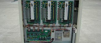
Everyone has probably ever thought about the question of how much a particular household electrical appliance consumes. For example, how much energy does a TV consume in standby mode? How does the energy consumption of a refrigerator change in different operating modes? For these purposes, you will need an AC wattmeter, and in the article we will look in detail at the design of one of the device options (Figure 1).
| Picture 1. | Digital AC wattmeter. |
It makes no sense to develop such devices for direct current due to the fact that in this case everything is very simply calculated using known laws and mathematical formulas, and only an ammeter is required from the measuring instruments. For alternating current, everything is a little more complicated and previously analog wattmeters for alternating current, although they provided high accuracy, were difficult to manufacture, not to mention digital wattmeters and the ability to assemble such devices at home. Modern technologies and element base make it possible to design multifunctional devices at minimal cost. Cheap microcontrollers (MCUs) with rich peripherals and powerful computing capabilities significantly simplify the creation of various automation and control systems. Integrated precision analog peripherals, and in some microcontrollers a digital signal processing subsystem, make it possible to develop multifunctional measuring instruments.
The digital wattmeter, the design of which we will consider, is designed to measure the power consumption of devices connected to an alternating voltage network of 207 - 235 V / 50 Hz. The main element of the wattmeter is an 8-bit PIC microcontroller from Microchip PIC18F252 series, which, using external ADCs, measures the current flowing through the load, the voltage across the load, calculates the effective value of the voltage (effective value) in the network, the effective value of the current and the average value of power consumption. All specified parameters are displayed on a two-line character LCD indicator.
The device does not have a separate power source. A built-in mains power supply is used, due to which the microcontroller part of the device is completely isolated from analog nodes that are under mains voltage.
Digital wattmeter - DIY
In our everyday life we use many different devices with different power consumption.
If it is necessary to do this, many ask the question of how to correctly determine the power so as not to overload the 220V network, what device is needed for this, etc. To measure the power consumed by a device, you need a wattmeter, for example, a TV, receiver, tape recorder, homemade amplifier, etc.
To use it for your amateur radio purposes, you can make a simple amateur radio wattmeter. The error of this device is insignificant, but it is enough to make it from several parts, which significantly reduces the cost of the design of the device and allows it to be manufactured even by a novice radio amateur with little design experience. The schematic diagram of a simple amateur radio wattmeter is shown in Fig. 1.
Fig.1.
The basis of the device is an alternating current voltmeter already known to you, which includes a dial indicator PA1, diodes VD1, VD2 and resistors R1, R3. Resistor R3 bypasses the indicator - microammeter M2003, to obtain a milliammeter with a needle deflection current of approximately 1 mA, and trimming resistor R1 sets the more precisely selected measurement range, in this case 100 W.
A voltmeter is connected in parallel to resistor R2, which is located in the load power circuit - between the XP1 power plug and the XS1 socket. When the wattmeter is plugged into the network, and the power plug of a load, say, a table lamp, is inserted into the socket, a current flows through resistor R2, the greater the power consumed by the load. This means that the voltage drop across resistor R2 will depend on the load power - this is what the voltmeter measures.
What parts will be needed to build this device? First of all, of course, the dial indicator. Although in this case it is the same as in the previous device, it is possible to use another indicator - with a total needle deflection current of 1 mA and any internal resistance. In this embodiment, resistor R3 is not needed. Diodes - any from the D9 series, trimming resistor also of any type, for example SPO.
Resistor R2 is a wirewound, very low resistance - 2 Ohms. You can make it yourself from a wire with high resistivity, for example, nichrome, constantan, manganin, but most likely you won’t be able to find such a wire and you will only have at hand a PEV or PEL copper wire in varnish-resistant insulation.
Then cut 3.6 m of such wire with a diameter of 0.2 mm, wind it around the body of the MLT-2 resistor with a resistance of at least 100 Ohms and solder the ends of the wire to the terminals of the resistor - the resistance of the resulting resistor will be approximately 2 Ohms.
There are few parts in the device, and they can be mounted on a small strip of insulating material mounted on the terminals of the dial indicator. The indicator itself is placed on the front panel of the case, and a power socket is attached to the side wall of the case.
Having plugged in a 100 W table lamp, apply mains voltage to the wattmeter and move the trimmer resistor slider to set the indicator needle to the final scale division.
Attention! Be careful to set the indicator needle to the final scale division only with a screwdriver with an insulated handle!
The wattmeter scale will be uneven because diodes work in it. Therefore, it is advisable to characterize the device, as was done in the previous design. To do this, you need to turn off the resistor R2 and apply a constant voltage (approximately from 0 to 1 V) from an regulated source to the upper contacts of the XP1 plug (plus) and the XS1 socket (minus). In this case, you should not shift the trimmer resistor slider.
After this, check the readings of the wattmeter, counting them using a graph - the characteristics of the diode and plugging lamps of different powers into the socket of the device - 75 W, 60 W, 40 W. Is it possible to measure relatively low power consumption with our wattmeter, say 5 or 10 W?
This is possible if you know one “trick”. Insert a tee into the wattmeter socket and plug in its lamp, for example, with a power of 60 W, into one of the pairs of sockets. Then insert the plug of the controlled low-power device into the other pair of sockets, and notice the increase in the indicator readings - it will be equal to the power consumption of the device.
For those who want to build a wattmeter with a power of 200 W or 500 W, we recommend reducing the resistance of resistor R2 to 1 and 0.5 Ohms, respectively, to avoid excessive voltage drop across it. Naturally, a multi-range wattmeter option is possible if you install a switch in it and connect resistors of different values instead of R2. We hope that you can design such a device yourself and use it for your amateur radio needs.
Schematic diagram
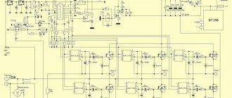
The circuit diagram and PCB design were developed in the free SoloPCB tools design environment. The schematic diagram of the device is shown in Figure 2. A complete list of components used is given in Table 2.
| Figure 2. | Schematic diagram of a digital AC wattmeter. |
To calculate power consumption, we need to know the voltage across the load and the current consumed by the load. The voltage to be measured is the AC mains voltage, so it must be taken into account that it can be in the range of 207 V - 253 V. In order to increase the accuracy of measurements, it is necessary to measure the mains voltage, rather than using a fixed average value of 230 V in calculations .
The mains power lines are connected to connector J1 (AC IN, AC input). The analog node for measuring network voltage consists of a resistive divider (R1, R2 R3), a precision reference voltage source (U3) and an ADC (U5). A resistive divider connected between phase and neutral is designed to reduce voltage scaling with a coefficient of R1/(R1+R2+R3)=1/201. This way we reduce the ±320V peak voltage to ±1.59V. We then use the REF03 (Analog Devices) voltage reference to offset this voltage up by 2.5V so that the ±320V range matches the input range ADC 0.91 V – 4.09 V.
Classification of wattmeters
Before measuring power with a wattmeter, current and voltage are first measured in the area under study. In order to obtain clear summary information, this data should be converted using wattmeters, which can be analog or digital.
For a long time, most of all measurements were carried out with analog devices, which in turn were divided into the categories of indicating and recording. They display the value of active power at a given section of the circuit. A typical representative is considered to be an indicating device with a semicircular scale and a rotating arrow. The scale is marked with a graduation corresponding to the values of the increasing power, which it measures in watts.
Another type, a digital wattmeter, refers to measuring instruments capable of measuring not only active, but also reactive power. All such devices are equipped with a display, which, in addition to power, displays current, voltage, and energy consumption readings over a certain period of time. The most advanced devices are connected and allow the data obtained to be output to a computer located remotely from the measurement site.
List of components used
| Designation in the diagram | Name, denomination | Housing, note |
| U1, U2 | 78L05 | SOT-89 |
| U3 | REF03 | SO-8 |
| U4 | ACS712-20A | SO-8 |
| U5, U10 | MCP3202-BI/SN | SO-8 |
| U6, U7, U8 | HCPL-0630 | SO-8 |
| U9 | PIC18F252-I/SO | SO-28 |
| BR1, BR2 | Diode bridge DF08S | 800 V / 1 A |
| TR1 | Transformer HR-E3013051 | 2 × 6 V, 1.5 VA |
| LCD1 | TC1602D | Two-line LCD indicator |
| C1, C18 | 470 µF 25 V | 10 mm × 10 mm |
| C2, C17 | 100 µF 16 V | 6.3 mm × 5.4 mm |
| C11, C12 | 22 pF 50 V | smd 0805, ceramics |
| C9 | 1 nF 50 V | smd 0805, ceramics |
| C2, C4, C5, C6, C7, C8, C10, C13, C22, C14, C15, C16, C17, C20 | 100 nF 50 V | smd 0805, ceramics |
| C21 | 1 µF 25 V | smd 1206, ceramics |
| R16 | 0 ohm | smd 0805, 1% |
| R2, R3 | 1 MOhm | |
| R5, R6, R17 | 1 kOhm | |
| R1, R14, R15, R18, R19 | 10 kOhm | |
| R7, R8, R9, R13 | 2.5 kOhm | |
| R4, R10, R11, R12 | 330 Ohm | |
| D2, D3 | Red LED | smd 0805 |
| D1 | Schottky diode SS14 | 1 A / 40 V, SMA housing |
| Y1 | Quartz crystal 20 MHz | |
| F1 | Fuse holder | Surface Mount |
| J1, J2 | Screw terminal block 1×3 | pitch 5.2 mm |
| J3 | Pin connector 1x5 | pitch 2.5 mm |
Printed circuit board
The PCB design was also done in the SoloPCB environment. Designing the instrument as a portable device was a good idea, with the PCB outline being designed in Autocad and then exported to the SoloPCB environment (Figure 5).
| Figure 5. | View of the digital wattmeter printed circuit board project in the SoloPCB environment. |
The printed conductors of the power lines (phase, neutral, ground) connecting the input (AC IN) and output (AC OUT) connectors are made as wide as possible, all blocking capacitors are located as close as possible to the microcircuits. The analog (AGND) and digital ground (DGND) buses are separate. All components are located on the top layer.
Note:
When designing the circuit and PCB in the SoloPCB environment, some elements that were missing in the libraries were created manually. A library of these elements is included in the archive with project files, which you can download in the downloads section.
DIAGRAM OF A SIMPLE WATTMETER
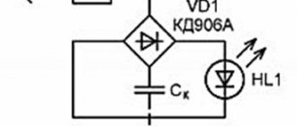
If you need to make a device to measure the power consumption of household appliances. It is not necessary to complicate the circuit with microcontrollers, LCD indicators and other expensive radio components. This design doesn't even require transistors. It is enough to feed part of the current from the consumer through a small transformer to a diode rectifier, and then to a dial indicator, in order to have a fairly accurate power indicator up to 1 kilowatt. If necessary, you can increase this range to at least 10 kW.
AC Power Meter
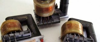
The basis of the device’s operation is a current transformer, which is essentially the same as a regular transformer. One winding consists of 3000 turns of thin wire wound on an iron core - this is the secondary winding. The primary winding is a pair of turns of the power cord. The ratio of current flowing through the primary side and the secondary winding is the inverse ratio of the number of turns. The linearity will not be ideal, but it will be good for average accuracy. In the end, whether the device consumes 540 watts or 580 is not very important. The half-wave rectifier consists of a small capacitor and germanium diodes; the forward voltage drop during the transition is measured by a 100 μA indicator. You can select the measurement limit of 1000 W and 100 W by connecting a resistor in parallel with the pointer head.
During testing and adjustment (selecting resistance), a 100 W incandescent lamp and a 500 W spotlight were used. That is, connect a load whose power you know in advance, and use it to set the required indicator readings. The finished wattmeter can be placed in any plastic box, or built into a surge protector. In this case, you will need to find a small switch, such as a recording level indicator from an old tape recorder.
Originally posted 2019-04-16 17:00:44. Republished by Blog Post Promoter
Source
Operating principle of an analog wattmeter
The basis of the design of the most common analog wattmeters is the electrodynamic system. Devices of this type make it possible to make the most accurate measurements and obtain the necessary results.
The operating principle of an analog-type wattmeter is based on two interacting coils. The first coil is stationary; its design uses a thick winding wire with a small number of turns and low resistance. This coil is connected in series with the consumer.
The second coil is in motion. A thin conductor with a large number of turns and high resistance is used for its winding. This coil is connected in parallel with the consumer and is equipped with additional resistance to protect against winding short circuits.
When the wattmeter is connected to the network, magnetic fields appear in the windings of its coils, interacting with each other. Due to this interaction, a torque is generated that deflects the moving winding by the calculated angle. This indicator is influenced by the product of current and voltage at a specified point in time.