Purpose and scope
UZM-51M (multifunctional protective device) is used to protect electrical equipment from voltage surges in single-phase electrical networks of any premises.
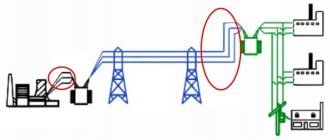
This device turns off consumption sources when the supply voltage increases or decreases, and also dampens its pulsed high-voltage surges. The reasons for these deviations may be different:
- overload of transformer substations;
- turning on powerful asynchronous motors and welding machines;
- short circuit or break of the neutral wire;
- lightning striking a power line.
UZM-51M is usually used in household electrical networks, installed after the electric meter and circuit breaker at the power supply input to the room. It can also be used in three-phase networks.
Important. For complete comprehensive protection, UZM-51M is installed together with other residual current devices.
Analogs
Analogues of the UZM-51 device include the following devices:
- OM-63 from ;
- RN-106 from NovaTek.
RN-106 is a voltage relay that protects against unauthorized entry into an apartment with a voltage of 380 V. Too high a voltage leads to the failure of all household appliances connected to the network at that moment.
Voltage relay RN-106 prevents failure of home appliances
The OM-63 power limiter is used primarily in single-phase networks. The device immediately turns off the power supply to the home when the power consumption exceeds the established threshold. The device also protects electrical equipment connected to the network from the negative effects of significant voltage drops from nearby lightning strikes or the inclusion of overly powerful equipment.
Principle of operation
Using the regulators installed on the device body, you can set the relay operation limit for the upper voltage from 240 V to 290 V and for the lower voltage from 210 V to 100 V.
When connected to the power supply, the indication on the UZM-51M does not work within the first 5 s. A flashing green light indicates that voltage testing is in progress. If it corresponds to the specified parameters, the electromagnetic relay turns on, and this is indicated by the uniform illumination of the yellow and green LEDs.
Reference. You can speed up the startup of the protective device by pressing the “Test” button.
In normal operation, the UZM-51M controller constantly monitors the voltage level, and the varistor dampens its pulses to an acceptable value.
Where to install UZM
As we said earlier, a voltage relay can be installed at the entrance to an apartment or house, or at all or some groups of consumers. Sometimes it can be difficult to choose a place to install the UZM. What can be said for sure is that it is placed after the introductory machine and, most often, after the electric meter. In principle, it can be installed before the meter, but only if the operating organization agrees. And they rarely give consent to this. Therefore, usually, the UZM is placed after the meter.
Two scheme options with UZM
The power supply circuit may also contain a fire protection RCD. So where should you put the surge protection device? Before the fire protection RCD or after? If you put it in front, then when the power is turned off it will be out of action. And if after, it may be damaged as a result of jumps. In general, decisions here are made individually. We can definitely say that the voltage relay must be installed before the first branch to consumers.
Connection in three-phase networks
There are special models of protective modules for three-phase networks - UZM-3-63. All three phases are connected to this device at once, and further supplied from the output. When triggered, all phases are switched off simultaneously, so that the power is lost completely. This is not always convenient, since problems usually arise with one of the phases.
Connecting a three-phase UZM
The issue can be resolved by installing one UZM for each phase. Then, if there is a imbalance at some phase, the rest will be in operation. It's more convenient. But this connection method - three single-phase UZMs - is not suitable if there is a three-phase load. In this case, when installing three separate UZMs, when disconnected in one of the phases, there may be a “flow” through the load to the adjacent one. So the choice is yours.
Appearance and design
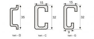
UZM-51M, like other modular devices, is mounted on a standard DIN rail. The relay housing is plastic, with two upper and two lower tunnel-type terminals.
On the front of the panel there are two rotating regulators that set the maximum and minimum voltage limits for the relay to operate, two transparent eyes and a “Test” button between them.
The lower eye glowing red means the emergency mode is turned on. The green glow shows that everything is normal. If the top eye glows yellow, it means that the electromagnetic relay contacts are closed.
The test button not only turns the device on and off, but also sets the restart time.
Inside the case there is an electromagnetic relay, a microcontroller and a varistor. The relay contacts break the phase wire, and the neutral wire passes directly through the housing as a bus.
False alarms or why ultrasonic monitoring does not work
Another point that must be taken into account when using such relays is surge protectors. When a test box is plugged into their socket, the AFIS may also not work.
They contain varistors that absorb impulses from the simulator, hence the whole problem. Therefore, be careful when checking and conducting such experiments for performance.
But what should you do if the sockets to which the spark protection does not respond are still identified? There are two ways:
install an additional AFDD as close as possible to the remote socket group
expand the area using a regular extension cord without a filter
Is the UZIS-I-002 simulator suitable for testing relays from other manufacturers? No one can give you guarantees on this question.
In different models, sparking is detected by different signs. A universal testing device can only be a real spark generator. But this thing is not cheap and large in size.
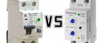
The UZIS, like the UZM 51MD, has an additional function. It cuts off the electricity when there is overvoltage.
However, unlike the UZM-ki, the Ecolight device does not protect against low voltage.
However, this is still convenient, since you do not need to have two different modular devices that take up additional space in the electrical panel. It is enough to purchase one, two standard modules wide.
The main difference between UZIS and UZM in this regard is that it does not turn on independently after the voltage parameters are restored to normal. Here the tongue, as on machine guns, will have to be cocked manually.
The following can be said about false positives. Drills and vacuum cleaners do not cause them, you can rest assured.
By the way, according to GOST, all spark protection devices must be tested with a whole set of varied loads. This includes halogen and fluorescent lamps, capacitor-start motors, etc.
But there are no welding machines there. As for them, without additional filtering, false alarms are possible on inverter devices.
At the same time, an ordinary transformer welder does not cause anything like this. Although it would seem that its direct purpose is to spark and give an arc.
The problem with inverters is typical for almost all such devices from different manufacturers. Apparently this is why the creators of GOST did not include it in their document.
The price of the device may seem overpriced to many (about 4,500 rubles), but double protection against fire and overvoltage is worth it. Despite the fact that foreign models from ABB, Hager and others are not yet particularly widespread in our market.
Operating instructions – download.
Technological map for installation - download.
Main technical characteristics and dimensions
- UZM-51M operates at a rated voltage of 220 V with a frequency of 50 Hz;
- maximum voltage - 440V with a frequency of 50 Hz;
- rated current - 63 A;
- maximum current - 80A;
- rated load power - 15.7 kW;
- maximum power - 20 kW;
- maximum absorption energy - 200 J;
- when the voltage increases, the shutdown threshold can be changed from 240 V to 290 V;
- when the voltage decreases, you can change from 100 V to 210 V;
- deviation of threshold values is no more than 3%;
- pulse protection is triggered in less than 25 ns;
- it is possible to switch the restart time from 10 s to 6 min;
- operating temperature from -25°С to +55°С;
- overall dimensions - 83x35x67 mm;
- weight - 140 g;
- service life of at least 10 years.
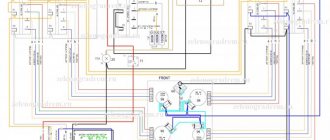
Connection diagrams
Figure 1 shows a typical connection diagram for UZM-51M.
In Fig. Figure 2 shows a diagram that allows the neutral wire to be connected on only one side, which makes it possible to combine the neutral terminals on one common terminal block.
In Fig. Figure 3 shows a diagram that allows you to disconnect the load with an additional switch.