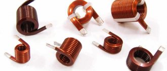
Species and types
There are low-frequency and high-frequency models. Screw and spiral coils are classified into a separate category. There are also modifications that are used in radio engineering. They are suitable for protecting capacitors or resonant circuits.
Devices in radio engineering
For transformers, coils with a cascade amplifier are suitable. The last category includes variometers; the main difference is the high frequency of the oscillatory circuits. Chokes can be single or double. The inductance and power supply of the system depends on this.
Low frequency
To be included in an electrical circuit, a low-frequency inductor is used. It is designed to suppress alternating current. The formula takes into account cyclic frequency and inductance values. The devices are based on a core made of steel. It can be with or without filters.
You may be interested in Installing an RCD in an apartment
To influence the frequency, a game is played with resistance. In a DC circuit, the voltage must remain constant. Filters are used to reduce the frequency. The main problem is the small capacity. To familiarize yourself with the inductor in detail, it is worth learning more about the resonant frequency, which stands out on the operating signal circuit.
When voltage increases in the circuits, stress is placed on the frame. The DC circuit uses opaque wirewound resistors. Single-layer universal-type coils are also suitable for these purposes. Their peculiarity is the use of ferrite rods.
Low frequency coil
High frequency
The devices are manufactured with different types of winding. We are talking about a set of advantages that save in a given situation. The scope of application of the elements is wide, taking into account the significant modulation frequency. In this way, it is possible to combat the increased resistance of metals. The coils have a core.
The main task is modulation of the generator frequency. It occurs due to signal amplification, and the process can be monitored by connecting an oscilloscope. Many high-frequency coils are not stable because they use a ceramic frame. It has a short shelf life, plus they are susceptible to high humidity.
Interesting! Modern products are made of aluminum and are compact.
Electricians are familiar with circuit and non-circuit modifications of high frequency. Depending on the winding, the stability of the electrical parameters is taken into account. High frequency models may use magnets and wires. We are talking about powder materials made from dielectrics.
The manufacturing process is associated with the cold pressing method. Inductive sensors differ in their protection. At enterprises, elements can be immersed in a solution or threaded into a tube. This is done to avoid short circuits. Global manufacturers solve the problem by using a secondary coil.
High frequency coil
The models have significant resistance and have a problem with electrolyte concentration. This changes the properties of the inductor. The conductivity of the solution decreases and the frequency of the electromagnetic field increases.
Designation, parameters and types of inductors
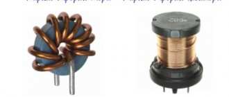
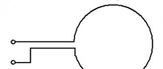
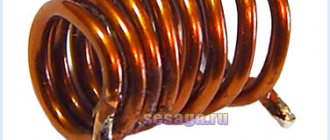
One of the most famous and necessary elements of analog radio circuits is the inductor. In digital electronic circuits, inductive elements have practically lost their relevance and are used only in power devices as smoothing filters. Inductors on circuit diagrams are designated by the Latin letter “L” and have the following image. There are dozens of types of inductors. They come in high-frequency, low-frequency, with and without tuning cores. There are coils with taps, coils designed for high voltages. For example, this is what frameless reels look like. Coils for microwave equipment are called microstrip lines.
They don't even look like coils. An effect called resonance is associated with inductance coils, and the brilliant Nikola Tesla received millions of volts from resonant transformers. The main parameter of a coil is its inductance. The inductance value is measured in Henry (H). This is a fairly large value and therefore in practice smaller values are used (mH, mH - millihenry and μH, μH - microhenry) 10 -3 and 10 -6 Henry, respectively. The coil inductance value is indicated next to its symbolic image (for example, 100 μH). In order not to get confused in microhenry and millihenry, I advise you to find out what the abbreviated notation of numerical values is.
Colored markings.
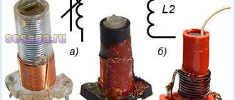
Many factors affect the inductance of a coil. These are both the diameter of the wire and the number of turns, and at high frequencies, when frameless coils with a small number of turns are used, the inductance is changed, bringing adjacent turns closer or apart. Often, to increase the inductance, a ferromagnetic core is inserted into the frame, and to reduce the inductance, the core must be brass. That is, you can get the required inductance not by increasing the number of turns, which leads to an increase in resistance, but by using a coil with a smaller number of turns, but using a ferrite core. An inductor with a core is depicted in the diagrams as follows.
In reality, a coil with a core may look like this. You can also find inductors with a tuning core. They are depicted like this. A coil with a tuning core looks like this in real life. Such a coil, as a rule, has a core, the position of which can be adjusted within small limits. In this case, the inductance value also changes. Trimmer inductors are used in devices that require one-time tuning. In the future, the inductance is not adjusted. Along with trimming coils, you can also find coils with adjustable inductance. In the diagrams, such coils are designated like this. Unlike trimmer coils, adjustable inductors allow multiple adjustments of the core position, and therefore the inductance. Another parameter that occurs quite often is the quality factor of the circuit.
The quality factor refers to the ratio between the reactive and active resistance of an inductor. The quality factor is usually in the range of 15 - 350. Based on an inductor and a capacitor, the most necessary unit of radio engineering devices, an oscillatory circuit, is made. The diagram shows the input circuit of a simple radio receiver designed to operate in the medium and long wave ranges. Currently there are practically no stations in these ranges. Inductor L1 has a sufficiently large number of turns to cover the maximum range. To improve reception, an external antenna is connected to the first winding L1. This can be a simple piece of wire up to two meters long.
Due to the large number of turns in inductance L1, there is a whole spectrum of frequencies and at least five to six working radio stations. Two inductances L1 and L2 wound on one frame constitute a high-frequency transformer. In order to select a station on inductor L2 that operates, say, at a frequency of 650 KHz, it is necessary to adjust the oscillatory circuit to this frequency using a variable capacitor C1. After this, the selected signal can be applied to the base of the transistor of the high-frequency amplifier. This is one of the uses of an inductor. The output stages of radio and television transmitters are built on exactly the same principle, only in reverse. The antenna does not receive a weak signal, but transmits EMF into space.
Designation of inductors.
Inductance
Any inductor has inductance . The inductance of the coil is measured in Henry (H), denoted by the letter L and measured using an LC meter.
What is inductance? If an electric current is passed through a wire, it will create a magnetic field around itself:
Where
B — magnetic field, Wb
I - current strength, A
Let's take this wire and wind it into a spiral and apply voltage to its ends
And we get this picture with magnetic lines of force:
Roughly speaking, the more magnetic field lines cross the area of this solenoid, in our case the area of the cylinder, the greater the magnetic flux (F) will be. Since an electric current flows through the coil, it means that a current with Current Strength (I) passes through it, and the coefficient between the magnetic flux and the current strength is called inductance and is calculated by the formula:
Calculation of the inductance of some types of high-frequency coils
Here are the calculation formulas for the most commonly used structures.
Inductance of a straight wire with a circular cross-section. This includes inductive elements of the DCV range, assessment of the inductance of the wire leads of resistors, capacitors, active elements:
Lpr = 0.002l(ln [4l/d]-1.75); lLprl = µH ,
where [l] = cm - wire length; d = cm - diameter of the wire without insulation.
Inductance of a round turn of circular wire. Used to evaluate the inductance of loop (resonant) antennas, communication coils, etc.:
Lcr = 0.00628V (ln [8D/d]-1.75),
where [D] = cm is the diameter of the coil.
The inductance of a closed geometric loop will always be less than the inductance of a straight wire of the same length. The greatest inductance is that of the closed geometric contours of the same perimeter that has the largest area. Consequently, the greatest inductance will be in a circuit shaped like a circle.
Inductance of a single-layer cylindrical coil (Fig. 4.2).
Rice. 4.2. Elements of a single-layer cylindrical coil
If the winding length l = m • N ( N is the number of turns ) corresponds to the inequality l >> D , then the formula is acceptable
L = π2 D2 N2 10-3 / l µH.
If the winding length of the coil is commensurate with its diameter, then a correction factor L0 . The value of this coefficient is found from the graph shown in Fig. 4.3, and the inductance value is determined from the expression
L = L0 • N2 • D • 10-3 µH,
Rice. 4.3. Graphical dependence of the correction factor
Inductance of a multilayer cylindrical coil. To obtain large inductance values, multilayer coils are used. The inductance of such coils can be determined using the previous formula, but the correction factor L0 (Fig. 4.4) will depend on the ratio of the winding thickness to the outer diameter t/D .
Rice. 4.4. Correction factor for multilayer coil
Inductance of a coil with a core . The use of cores makes it possible to obtain the optimal value of inductance and quality factor and ensure precise setting of inductance. Inductance of a coil with a core LC = μСL , where L is the inductance of the same coil without a core; μC is the effective magnetic permeability. If μ is the magnetic permeability of the material from which the core is made, then the ratio K μ = μс/μ is the coefficient of use of magnetic properties. It depends on the design of the coil and is determined experimentally.
For ferromagnets (ferrites, carbonyl iron) μс > 1 , for diamagnetic materials (brass, copper, aluminum) μс < 1 . Thus, using ferromagnets increases the inductance of the coil, and using diamagnets decreases it.
The inductance of a toroidal coil (with a ring core) is determined by the formula
Ltor = 0.00628 • μ • N2 (D - √D2T - Dв),
where DT is the diameter of the center line of the torus, cm; DB is the average diameter of the coil; μ is the initial magnetic permeability of the torus material.
Inductance of the shielded coil. Shielding is performed either by shunting the magnetic field with a ferromagnetic screen with a high relative magnetic permeability or by displacing the magnetic field with a diamagnetic screen (copper, brass, aluminum). To shield RF coils, as a rule, the second method is used.
Inductance of a cylindrical coil with an aluminum cylindrical screen
L = L • [1-(D/Dе)3] • [1-(I/2Iе)2],
where L is the inductance of the coil without a screen; D —winding diameter; DE - screen diameter; l —winding length; lE is the length of the screen. The quality factor of a shielded coil is always lower, and its own capacitance is higher than that of a coil without a shield.
Why are bifilar inductors needed?
Sometimes the coil is wound into two or more wire strands. Tesla used the design to increase capacitive qualities. As a result, it became possible to save materials - they said above. As for the state of the art at the current stage of technology development, the reason for the creation of bifilar coils may be the following:
Bifilar inductors
- One winding is grounded. Eliminates parasitic back-EMF that causes sparking and some other negative effects. When the voltage suddenly disappears, the magnetic field mostly induces current in the grounded winding, since the active resistance of the circuit is the smallest. The back-EMF effect is extinguished. In impulse relays, the auxiliary winding is short-circuited. The field energy is low and is dissipated by the active resistance of copper in the form of heat.
- Tesla's ideas have not been forgotten. Low value resistors are often made in the form of bifilar coils. Resistances often have a similar structure. For example, the well-known MLT, the tape is wound on a ceramic base. The essence of the idea is to increase capacitance, compensating for inductance. The resistor impedance becomes purely active. The meaning of the event is great when working on alternating current. In DC circuits, the imaginary part of the impedance (reactance) does not play a role.
- In switching power supplies, the voltage is of the same polarity and varies in amplitude. It will allow the bifilar transformer to be protected from the phenomenon of parasitic back-EMF, saving the key transistor from breakdown. The additional winding is grounded through a diode; in normal mode it does not affect the operation of the device. The back EMF is in the opposite direction. As a result, the pn junction opens, the potential difference is limited by the forward voltage drop. For silicon semiconductor diodes, the value is 0.5 V. It is clear that the voltage cannot penetrate a switching transistor of almost any type.
- Tesla's ideas are used in the creation of perpetual motion machines (in the literature: SE - superunit devices, with an efficiency above 1). The ability to eliminate reactance is used to idealize the work process.
Ferrite magnetic cores, coils with ferrite cores
Ferrites, which have become widespread in the last three decades, are solid solutions of metal oxides or their salts that have undergone special heat treatment (roasting). The resulting substance - semiconductor ceramics - has very good magnetic properties and low losses even at very high frequencies.
Before the introduction of GOST 2.723-68, magnetic cores made of magnetodielectrics and ferrites were designated on the diagrams in the same way - with a thickened dashed line.
Marking colors.
The ESKD standard left this symbol for magnetic cores made of magneto-dielectric, and for ferrite ones it introduced a designation that was previously used only for magnetic cores of low-frequency chokes and transformers - a solid thick line. The fears of some experts that the same designations of coils with magnetic cores made of steel and ferrite would make it difficult to read the circuits were not confirmed
The fact is that when studying circuits, attention is paid not only to the symbols of individual elements, but also to how they are connected to each other in a particular functional group, what place these groups occupy in the signal conversion chain
And if, for example, the cascade is radio frequency, then a coil with a solid magnetic core cannot be confused with a low-frequency choke. According to the latest edition of GOST 2.723-68 (March 1983), the magnetic circuits of the coils are depicted by lines of normal thickness. Wanting to show in the diagram a coil whose inductance can be changed using a magnetic circuit, a tuning control sign is introduced into its symbol. This can be done in two ways: either by crossing the designations of the coil and magnetic circuit with this sign.
To tune coils at frequencies above 15...20 MHz, magnetic cores made of so-called non-magnetic materials (copper, aluminum, etc.) are often used. The eddy currents arising in such a magnetic circuit under the influence of the magnetic field of the coil create their own field, counteracting the main one, as a result of which the inductance of the coil decreases. A non-magnetic magnetic trimmer is designated in the same way as a ferrite one, but the chemical symbol of the metal from which it is made is indicated next to it (in the coil designation shown in Fig. 6c, a trimmer made of copper is shown).
How are inductors different?
These circuit elements have a large number of types and types, which depend on the method and purpose of their use. Sometimes they are divided by frequency. Among them are the following types:
- Low frequency devices. They are used as chokes in fluorescent light bulbs, transformers (all windings can be considered inductive coils), and as a filter against magnetic interference. The core is made from electrical steels, or laminated cores are usually made from sheets (for alternating current circuits).
- High frequency devices. They are used in radio receivers, to amplify the communication signal, as accumulation and smoothing of chokes in power supplies operating pulsed. The core in this version is made of ferrite.
Its design features depend on the parameters of the inductance device.
Winding is carried out both in one and in several layers, wound to the turns or at a distance from each other. At the same time, even the distance differs: depending on the length, constant and progressive steps of turns are distinguished. The final size of the coil depends on the choice of winding type and design.
A variometer is a coil where the inductance is variable, it is designed a little differently than standard coils.
There are different solutions for this type of coil:
- Sometimes the cores in them are movable;
- Several windings are placed on a single core in a series connection, the induction varies depending on their placement;
- The coil can be expanded or narrowed; the decrease and increase in inductance depends on the winding density.
The rotor is the moving part of the coils. The stator is the stationary part. Winding methods can also be a classification for coils. For example, double-sided windings can eliminate interference in networks. Winding on one side eliminates differential interference.
Big encyclopedia of oil and gas. What are inductors and their classification
Reels
- these are wound or printed elements with inductive resistance. The coils are designed to convert the energy of an alternating electric field into the energy of an alternating magnetic field and vice versa, creating reactive inductive resistance to alternating current.
Classification.
Coils are classified according to several criteria. According to their design characteristics, coils are divided into cylindrical, toroidal, flat, single-layer and multilayer, with and without a core, shielded and unshielded. According to their use, coils are divided into: loop connections and chokes. The first are used in oscillatory circuits, the second - for connecting electrical circuits, and the third - for separating direct and alternating currents. According to the nature of the change in inductance, the coils are of constant inductance, tuning, and variable inductance (variometers), which differ from tuning coils in a wider range of changes in the nominal value.
Conventional images and symbols.
Conventional images of coils in the diagrams are shown in Fig. 1.
Rice. 1. Conventional images of coils in the diagrams: a, b - coils in the absence and presence of a magnetodielectric core; c, d - trimming coils; d - variometer
The only symbols have only standardized elements, these are coils with armored and toroidal cores. They combine the name of the ERE, the type of core, the number of the unified series, inductance, and tolerance. For example, KISB-9a-5-30±5% means inductor, armor core 9 a, unified row number 5, inductance 30 µH, tolerance ±5%.
Structure.
To manufacture coils, the following structural elements are required: frame, winding, framer, screen, fastening elements, elements of protection from external conditions. The frame is the structural basis of the coil. It is made mainly from plastic or ceramics in the form of a hollow tube with a smooth or cut outer surface (Fig. 2). Cutting the outer surface is necessary for winding in increments. The inner surface of the frame can also be smooth or cut. The cutting of the inner surface is intended for the builder. The frame may have one or several sections, elements for fastening to the board. High-power coils use finned frames that facilitate heat dissipation. External leads are pressed into plastic frames, and special grooves are left for them in ceramic frames. Sometimes, instead of a frame, a magnetodielectric core can be used, as, for example, in toroidal coils, or the coils can be made frameless. In the latter case, to ensure the necessary rigidity of the structure, a thick wire with a diameter of more than 1 mm, with a small number of turns (4 ... 6), is chosen for winding. The winding is designed to create an inductive effect. In single-layer volumetric coils it can be continuous or with a step (Fig. 3, a, b). In flat structures it has the shape of an Archimedes spiral (Fig. 2, c). In multilayer coils the winding is always continuous. It can be sectioned or non-sectioned, row, pyramidal or made “in bulk” (Fig. 3, d, e, f, g).
Rice. 2. Structural types of coil frames
Rice.
3. Main types of coil windings: a - single-layer continuous; b - single-layer with steps; c - single-layer flat; g - multilayer ordinary; d - multilayer “in bulk”; e - multilayer pyramidal;
g - multilayer sectioned In addition to those noted above, universal windings are widely used in multilayer coils (Fig. 4), in which the turns are not placed parallel to each other, but alternately from one edge of the coil to the other, intersecting at a certain angle.
Rice. 4. Universal winding: P
- Start;
K
- end of the turn;
— wire deflection angle;
— angle of intersection of the wire; p - number of transitions
Copper or silver-plated copper wire is most often used for winding. With single-layer winding with pitch, the wire can be without insulation, and with continuous single-layer and multi-layer winding, wires with enamel insulation are used. If it is necessary to ensure a small intrinsic capacitance of the coils, enameled wires are used, additionally covered with fibrous (silk) insulation or licendrate - multi-strand intertwined wire. In highly stable and powerful coils, winding is carried out in the form of silver-plated copper bars, embedded in a ceramic frame. The external leads of the coils are made of copper wire with a diameter of 0.5 ... 1.5 mm, which is pressed into a plastic frame or inserted into the grooves of ceramic frames. Coil cores can be cylindrical, coil, armored, W-shaped, toroidal, H-shaped (Fig. 5).
Rice. 5. Types of magnetic cores: a ... g - cylindrical with thread, smooth, with a sleeve, tubular; d, f - reel; g, h - armored with a closed and open magnetic circuit; and - cup; k - toroidal; l - ring; m - H-shaped; n - W-shaped
Solid cylindrical cores are most often used in tuning inductive elements, and tubular cores are used in ferrovarioters. Armor and cup cores, in turn, provide high quality factor of the coils, their shielding and make settings. Toroidal and annular cores reduce the size of coils due to low magnetic flux dissipation. Coil-shaped cores have an increased degree of utilization of the magnetic properties of the material, but cause large losses at high frequencies. W-shaped cores are used in those coils in which the inductance will be controlled by current. Since the coils are designed to operate at high frequencies, to reduce energy losses, the core for them is made of ferromagnetic dielectrics, which contain carbonyl iron, and ferromagnetic semiconductors, which are ferrites. For coils designed to operate on short and ultra-short waves, the cores are made of non-magnetic materials (copper, brass). The tuner is actually a core made of ferromagnetic or non-magnetic material that has a cylindrical shape and can be screwed into a frame, armor, cup or coil core to adjust the inductance of the coil (Fig. 5). Shielding of inductors is necessary to localize their own electromagnetic fields and protect them from external electromagnetic influences. For this purpose, cylindrical, less often prismatic casings (screens) are made from highly conductive conductor materials (most often aluminum or copper), which are reliably connected to grounding (Fig. 6). As a result, the currents induced in the screen are diverted to ground.
Rice. 6. Shielded coils
Coils are protected from external conditions by covering them with chemically resistant varnishes, leaking liquid dielectrics, or placing them in special sealed housings.
Job.
The operation of the coil is based on the fact that an alternating electric current flowing through the coil causes the appearance of an alternating electromotive force of self-induction in it, which prevents the current from changing, creating inductive reactance to it. The electromotive force of self-induction is directly proportional to the rate of change in current:
Coefficient L
, which is included in the formula, is called the self-inductance coefficient or the inductance of the coil. Reactance is directly proportional to the frequency of change of current and the inductance of the coil:
Ferromagnetic cores pick up the magnetic field lines of alternating electric current and, as a result, force them to intersect the turns of the coil to a greater extent, which leads to an increase in the self-induction emf, and therefore to an increase in the inductance of the coil. The action of non-magnetic cores is opposite to the action of their ferromagnetic counterparts. Adjustment of the coil inductance is based on the change in the magnetic flux passing through its winding. It can be carried out in several ways (Fig. 5): - by introducing a non-magnetic tuner into the coil, which pushes out the magnetic field lines of alternating current from it; — introducing a magnetic tuner into the coil, which increases the effective magnetic permeability; - changing the gap between the core and the coil; - a change in the magnetic permeability of the coil core when it is magnetized with a direct electric current; — moving turns, sections of coils.
Properties.
Since the coils operate at high frequencies and are intended primarily to create reactive inductive resistance to alternating current in electrical circuits, provide electromagnetic coupling between them, and high selectivity of oscillatory circuits, the main ones for them are the frequency characteristics, which express the dependence of their reactive and active resistances, as well as resistance losses in own capacitance and quality factor depending on frequency. The expression shows that the reactance of the coil to alternating current changes in direct proportion to the frequency (Fig. 7, line 1).
Rice. 7. Frequency dependences of reactive and active resistance and losses in the coils’ own capacitance
The active resistance of the coil wire with alternating current also increases with frequency (Fig. 7, curve 2) mainly due to the skin effect, turn effect and proximity effect. The losses in the coil’s own capacitance change similarly with frequency (Fig. 7, curve 3). The quality factor of a coil is determined by the ratio of its reactance to active resistance
Since at the beginning of the high-frequency range, with increasing frequency, the reactance grows faster, and at the end of it, the active resistance and energy losses in the own capacitance, screen and core grow faster, the curves of the frequency dependence of the quality factor have a maximum (Fig. 8).
Rice. 8. Frequency characteristics of the quality factor of coils with armored cores made of carbonyl iron (a) and ferrite (b)
Coils are characterized by the following parameters: inductance, quality factor, temperature coefficients of inductance and quality factor, aging coefficients of inductance and quality factor, self-capacitance and self-resonant frequency, reliability. The inductance of a coil characterizes the value of the electromotive force of self-induction, reactance, quality factor, and magnetic field energy induced in it:
where I
- current through the coil. The quality factor of the coils, which is determined by the ratio of reactance to active resistance, which characterizes the resonant properties (selectivity) of the oscillatory circuits, their efficiency. The temperature coefficient of inductance characterizing the temperature stability of the inductance of the coil is found as follows:
where and is the inductance value at temperatures and . The temperature quality factor is determined in the same way
where and is the value of the quality factor at temperatures and . Inductance aging coefficient, which characterizes the temporary stability of the inductance of the coils, is calculated using the formula:
where and is the value of the coil inductance at time and . The aging factor of the quality factor is determined similarly:
where and is the value of the quality factor at the moment of time and . The coil's own capacity is determined by its structural elements. Calculations do not provide the required accuracy, so it is advisable to determine it experimentally. Knowing the coil's own capacitance and inductance, one can find its own resonant frequency:
The reliability of the coil is determined by gradual failures caused by the aging of dielectrics and magnetic materials, and the oxidation of wires. These processes are accelerated by moisture and temperature. Protection from these destabilizing factors slows down the aging process and thereby increases the parametric reliability of the coils. The inductance of the coil under the conditions of the above factors can be determined by the expression:
where is a coefficient characterizing the change in the inductance of the coil under the influence of moisture. Reliability in this case is assessed by the probability of parameters not exceeding tolerance limits. Sudden failures affect the reliability of the coils to a certain extent. They are, of course, caused by a violation of the electrical connection of the winding with the terminals, winding breaks, short circuits of turns, and the like. Typical values of some of the above coil parameters are given in table. 1.4.
Table 1.4 Typical values of discrete coil parameters
The equivalent circuit of the coil must reflect its properties and contain not only the inductance of the coil itself, but also the inductance of the leads, the capacitance of the turns and leads, the capacitance due to the core, energy losses in copper, in capacitors, the core, and the like. But such an equivalent circuit can be simplified if both components of the inductance are combined into one inductance L
with energy losses, and all components of the container - into one container with energy losses. Then such a simplified equivalent circuit of the coil will have the form shown in Fig. 9, a.
Rice. 9. Simplified coil equivalent circuits
You can introduce the concept of equivalent coil inductance, which reflects the combined effect of inductance and capacitance:
This way you can find the equivalent inductance
where is the self-resonance frequency.
Similarly, we can introduce the concept of equivalent loss resistance:
Then the coil equivalent circuit can be simplified (Fig. 9, b).
Application.
Discrete coils are used in oscillatory circuits, electrical signal delay lines, and filters. They are used to create inductive reactance in certain sections of electrical circuits, to provide magnetic coupling between electrical circuits, to separate direct and alternating currents, and the like. Coils are difficult to microminiaturize, so there are practically no inductive elements in integrated circuits. An exception is thin-film hybrid ICs, in which they have the form of flat Archimedes spirals with an inductance of up to 10 μg. In semiconductor ICs, instead of coils, special circuits with transistors are used, which give an inductive effect. In thick-film hybrid ICs, the coils are predominantly used as hinged coils.
Design and calculation.
In coils, geometric dimensions, inductance, number of turns, wire diameter, energy loss, and quality factor are calculated.
The geometric dimensions of the coils are determined by their diameter D
, length, winding depth, and frame diameter.
In a single-layer coil, diameter D
is the diameter of the circle formed by the center line of the active cross-section of the wire.
At high frequencies, the diameter of the coil D
can be considered equal to the diameter of the frame. The length of the coil is the distance between the center lines of the outer turns. The distance between the center lines of adjacent turns is called the winding pitch. It is usually assumed that:
or
where N
- number of turns. With loose winding made with a looseness coefficient ≈ 1.05 ... 1.3
where is the diameter of the wire with insulation. For multi-turn single-layer coils it is assumed that:
For multilayer coils, we can assume that the outer diameter of the coil D
equal to the outer diameter of the winding, and its inner diameter . In this case, the winding depth
Average coil diameter:
For a simple regular coil and bulk winding, the depth
The inductance of single-layer solid-wound coils is determined by the expression:
where , , is a correction factor that depends on the ratio and is determined from the graph shown in Fig. 9, or approximately according to the expression:
Rice. 9. Dependency graph for single-layer coils
The inductance of a single-layer coil wound in increments is determined from the expression:
where is the inductance of the coil, A and B are correction factors, determined from the graphs shown in Fig. 10; d
- diameter of the wire without insulation. The inductance of a flat circular coil can be determined by the expression:
where b
— depth of flat winding.
Rice. 10. Dependency graphs and
The inductance of a flat square coil is calculated by the formula:
where is the length of the side of the middle square. The formula can also be used to calculate the inductance of multilayer coils, but for them the correction factor, which simultaneously depends on the ratios, is found from the graphs shown in Fig. 11. The inductance of a coil with a core that has magnetic permeability is times greater than the inductance of the same coil without a core, that is
So, calculating the inductance of coils with a core actually comes down to determining. For toroidal coils in which magnetic flux losses are small, where is the magnetic permeability of the core material. Therefore, the inductance of a coil with a toroidal core is found as follows:
where is the cross section of the core, is the average length of the magnetic field line. For other core shapes. So, for example, for an armor core
where is the length of the slit.
Rice. 11. Dependency graphs for multilayer coils
The inductance of shielded coils is determined by the expression:
where is the coupling coefficient between the coil and the screen.
For single layer coils
where is the diameter of the screen, is a coefficient that depends on the ratio and is determined from the graph shown in Fig. 12.
Rice. 12. Dependency graph
Page 1
Coils of variable inductance and mutual inductance, called variometers, with a smooth change in parameter, contain two coils, one of which is stationary (stator), and the second is rotatable (rotor) inside the stationary one. The same variometers, when the coils are connected to different circuits, give a variable mutual inductance, the value of which is calculated by the formula M 0 5 (L - L0), where L is the report on the inductance scale, and L0 (Lj L2) is the inductance of the coils indicated on the variometer panel .
Variable inductance coils (variometers) are used for smooth adjustment and tuning of oscillatory circuits, as well as for variable coupling with an antenna and in radio direction finders. Variometer designs vary in shape and size. In radio equipment, variometers are widely used, in which the inductance is changed by means of contacts sliding along the wire winding.
Variable inductance coils (variometers) are used much less frequently.
The variable inductance coil consists of two sections connected in series: the inductance of sections L is 200 µH and L2 is 85 µH. Calculate the total inductance of the coil if the magnetic fluxes of the sections are directed towards each other.
The variable inductance coil consists of two sections connected in series: the inductance of the sections Li is 200 µH and L2 is 85 µH. Calculate the total inductance of the coil if the magnetic fluxes of the sections are directed towards each other.
The cores of the variable inductance coils are made of ferrite grade 600NN, their length is 30 mm, diameter 3-26 mm.
Variometers are variable inductance coils that are used for smooth adjustment of circuits, for variable communication with an antenna and in radio direction finders.
Variable inductance coils and mutual inductance are used. Inductor stores, which are a set of inductor coils, are very convenient for measuring circuits.
Variable inductance coils and mutual inductance are used. Inductor stores, which are a set of inductors, are very convenient for measuring circuits.
Inductance in electrical circuits
While a capacitor resists changes in alternating voltage, inductance resists alternating current. An ideal inductance will have no resistance to direct current, however, in reality, all inductive coils themselves have a certain resistance.
In general, the relationship between the time-varying voltage V(t) passing through a coil of inductance L and the time-varying current I(t) passing through it can be represented as a differential equation of the following form:
When a sinusoidal alternating current (AC) flows through an inductor, a sinusoidal alternating voltage (EMV) is generated. The amplitude of the EMF depends on the amplitude of the current and the frequency of the sinusoid, which can be expressed by the following equation:
where ω is the angular frequency of the resonant frequency F:
Moreover, the phase of the current lags behind the voltage by 90 degrees. In a capacitor, the opposite is true, where the current leads the voltage by 90 degrees. When an inductive coil is connected to a capacitor (series or parallel), an LC circuit is formed that operates at a specific resonant frequency.
Inductive reactance XL is determined by the formula:
where XL is the inductive reactance, ω is the angular frequency, F is the frequency in hertz, and L is the inductance in henry.
Inductive reactance is the positive component of impedance. It is measured in ohms. The impedance of the inductor (inductive reactance) is calculated by the formula:
GENERAL ELECTRICAL ENGINEERING AND ELECTRONICS. ELECTRICITY AND MAGNETISM
|
Inductor
- is a passive component of electronic circuits, the main purpose of which is to store energy in the form of a magnetic field. The property of an inductor is somewhat similar to a capacitor, which stores energy in the form of an electric field.
Inductance (measured in Henry) is the effect of creating a magnetic field around a current-carrying conductor. The current flowing through the inductor creates a magnetic field, which has a relationship with the electromotive force (EMF) that opposes the applied voltage.
The resulting reaction force (EMF) opposes the change in alternating voltage and current in the inductor. This property of an inductive coil is called inductive reactance. It should be noted that the inductive reactance is in antiphase to the capacitive reactance of the capacitor in the AC circuit. By increasing the number of turns, the inductance of the coil itself can be increased.
Marking
When considering inductors, color and code markings are evaluated. If you look at the first numbers, the inductance indicator is displayed. Next, the deviation parameter is taken into account:
- Silver 0.01 µH, 10%.
- Gold 0.1 µH, 5%.
- Black 0.1 µH, 20%.
- Brown 1.1 µH.
- Red 2.2 µH.
- Orange 1 µH.
- Yellow 4 µH.
- Green 5 µH.
- Blue 6 µH.
- Violet 7uH.
- Gray 8 µH.
- White 9 µH.
Marking
In an unstable alternating electric current circuit, you cannot do without an inductor. The main types of insulated conductors are described above and their parameters are demonstrated. The frequency level is taken into account, as well as properties.
Color marking of chokes
In this article we will talk about determining the parameters of chokes using the table of color markings of chokes. The color marking of the chokes practically coincides with the color marking of the inductors. The structure of the chokes markings is as follows:
- the first two marks (stripes or dots) indicate the value of the nominal inductance in microhenry (µH);
- the third mark is the multiplier;
- the fourth mark is tolerance.
Most often, 4 or 3 colored stripes or dots are used to mark chokes. When using throttle markings with three marks, the default assumes a 20% tolerance. Let's look at examples of how the main parameters of chokes are determined.
Color coding of chokes.
Tags
features of the inductor. Inductor inductor induction coil current inductor coil work filters induction coil. coil type. spiral coils. suitable coils low frequency inductor. alternating current required current coil alternating current. and chains.
self-inductionandarticlelossvery-calledresponsecircuitssourcespresentsmomentstotalelectromagneticsitegraphics