What is power in electricity: simply about the complex
I remembered the epic about Ilya Muromets, when he applied all his power to the nightingale robber. The poor guy immediately started to see sparks coming out of his eyes, like the flames from the top picture on the incorrectly installed wiring.
In simple words: power in electricity is a power characteristic of energy, which is used to evaluate both the ability of generator sets to produce it and the capabilities of consumers and transport routes.
All these areas must be accurately assembled and adjusted to ensure safe operation. As soon as a malfunction occurs anywhere, an accident immediately develops in the entire circuit.
When it comes to home electrical equipment, you have to constantly strike a balance between:
- devices connected to the network;
- design of wires and cables;
- setting up protective devices.
Only a comprehensive solution to these three issues can ensure the safety of wiring and residents.
How to calculate electrical power at home
Formulas for calculating power in electricity allow you to perform a qualitative assessment of the safety of each of the above items.
They are not difficult to use. In previous articles I have already provided an electrician’s cheat sheet, where they are presented in a visual form for DC circuits.
They are completely valid for the active component of alternating current power that does useful work. By the way, besides it there is also a useless one - reactive, associated with energy loss. The second section is devoted to its description.
It is convenient to do such calculations using an online calculator. It eliminates routine mathematical calculations and arithmetic errors.
With any of the methods, to calculate active power, you need to know two of three electrical quantities:
- current strength I;
- applied voltage U;
- circuit section resistance R.
How to measure electrical power at home
There is another possibility for estimating active power: its measurement in an operating circuit using special devices: wattmeters.
An industrial laboratory wattmeter can provide accurate measurements. It is manufactured both as a device operating on analog signals and using digital technologies.
In household wiring, precise calculations are not needed. Various types of simpler wattmeters are produced for it.
Devices that can be plugged into an outlet and connected to a power cord from the consumer are popular, turn them on and immediately take readings on the display in watts.
They are called that: wattmeter socket. They measure pure active AC power.
Such devices relieve the electrician from performing complex operations under voltage when it is necessary to measure:
- effective voltage;
- current strength;
- phase shift angle between current and voltage vectors.
Then all the data additionally needs to be entered into the formula for calculating power by current and voltage, and calculations must be made using it.
This method can be simplified by carefully observing the electrical meter of a rotating disk induction system. It calculates the work done: the power consumed over a certain time.
However, the rotation speed of the disk precisely characterizes the amount of consumption. You just need to count how many times it turns around in a minute and convert it to watts according to the plate located on the case.
How to calculate power knowing current and voltage
The power characteristics of electrical installations are calculated using the formula:
We recommend reading: How to determine phase and zero: with an indicator screwdriver, multimeter, visually
P=U*I - direct current;
P=U*I*cos(phi) – alternating current of a single-phase network.
P=1.73*U*I*cos(phi) - three-phase network.
The article provides simplified formulas for calculating the active power of the electrical network, which give approximate results.
To obtain accurate results, it is also necessary to take into account reactance and ordinary resistance, as well as losses.
Why Circuit Reactance Affects AC Power
A sinusoidal voltage harmonic, entering a resistive resistance, changes the magnitude of the current without its deviation on the complex plane.
Such current performs useful work with minimal energy losses, generating active power. The frequency of the signal does not have any effect on it.
The resistance of the capacitor and inductance depends on the frequency of the harmonic. Its opposition deflects the direction of the current on each of these elements in different directions.
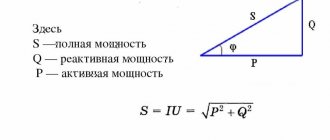
Such processes are associated with the loss of part of the energy for useless transformations. They consume power Q, which is called reactive. Its influence on the total power S and the connection with active P is conveniently represented graphically by a right triangle.
I wanted to draw it against the background of equipment made from piles of porcelain and metal, where I had to work for quite a long time. I got distracted. Don't judge harshly for this.
Compare it with the resistance triangle I published earlier. Do you find any common features?
They are the geometric proportions of the figure, the formulas describing them and the angle φ, which determines the total power loss. Let me move on to a more detailed consideration of them.
How to calculate correctly
Active power, how to make the correct calculation?
The power of the electric current affects how quickly the device can complete the job. For example, an expensive heater with twice the power will heat a room faster than two cheap ones with half the power. It turns out that it is more profitable to buy a unit with more power in order to heat a cold room faster. But, at the same time, such a unit will consume significantly more energy than its cheaper counterpart.
The power consumption of all appliances in the house is also taken into account when selecting wiring for installation in the house. If you do not take this into account and subsequently connect too many devices to the network, this will cause network overload. The wiring will not be able to withstand the power of the electric current of all devices, which will lead to melting of the insulation, short circuit and self-ignition of the wiring. As a result, a fire may start, which can lead to irreparable consequences.
Single-phase sinusoidal current in electrical circuits is calculated by the formula P = U x I x cos φ, where υ and Ι. Their designation is encrypted as follows: the root mean square value of voltage and current, and φ is the phase angle between them.
For non-sinusoidal current circuits, the electrical capacitance is equal to the square root of the sum of the squares of the active and reactive performance. Active performance is characterized by the speed of the irreversible process of converting electrical energy into other types of energy. This capacitance can be calculated through the current, voltage and active component of the circuit resistance r or its conductivity g using the formula P = I(2) xr = U(2) x g.
Reactive Power
It should be noted that:
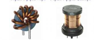
- The resistor consumes active power and releases it in the form of heat and light.
- inductance consumes reactive power and releases it in the form of a magnetic field.
- The capacitor consumes reactive power and releases it in the form of an electric field.
In any electrical circuit of both sinusoidal and non-sinusoidal current, the active capacity of the entire circuit is equal to the sum of the active powers of the individual parts of the circuit; for three-phase circuits, the electrical capacity is defined as the sum of the throughput of the individual phases. With the total performance S, the active one is related by the relation P = S x cos φ.
In the theory of long lines (the analysis of electromagnetic processes in a transmission line, the length of which is comparable to the length of the electromagnetic wave), the complete analogue of active power is transmitted power, which is defined as the difference between the incident power and the reflected performance.
How to find reactive apparent power through active power? This performance, which characterizes the loads created in electrical devices by fluctuations in the energy of the electromagnetic field in a sinusoidal alternating current circuit, is equal to the product of the rms values of voltage U and current I, multiplied by the sine of the phase angle φ between them: Q = U x I x sin φ (if the current lags behind the voltage, the phase shift is considered positive, if it is ahead, it is negative).
Reactive quantity designation
An example of calculating the power of electric current
In the end, you will be able to test your knowledge with 2 common examples.
Imagine that in the first problem you have a resistor R = 50 Ohm through which an electric current I = 0.3A flows. What electrical power is converted in this resistor?
You can find the solution by finding the appropriate formula and plugging in the given values into it. That is, we get: P = I2R = 0.32 * 50 = 4.5 W
In the second problem, a resistor R is given, the electrical resistance of which is 700 Ohms. The technical description states that the maximum power of this resistor is 10 W. How high can the voltage applied to this resistor be?
To solve this problem, we select the appropriate formula: P = U2/R, from where we find Umax = Pmax * R = 700 * 10 = 83.67 V.
This means that the maximum voltage can be 83.67 V. To be on the safe side, you should choose an electrical voltage well below this limit.
Formulas for calculating power for single-phase and three-phase power circuits
In the ideal theoretical case, a three-phase circuit consists of three identical single-phase circuits. In practice there are always some deviations. But, in most cases, they are neglected in analyzes.
Therefore, we consider the simplest question first.
Graphs and formulas for single-phase voltage
How does a resistor work?
On a purely resistive resistance, the sinusoids of current and voltage coincide in angle and are directed equally at each half-cycle. Therefore, their product, which expresses power, is always positive.
Its value at an arbitrary moment of time t is called instantaneous, denoted by the lowercase letter p.
The average power value over one period is called the active component. Its graph for alternating current has the shape of a symmetrical burst with a maximum value of Pm in the middle of each half-cycle T/2.
If we take half of its value Pm/2 and draw a straight line during one period T, we will get a rectangle with ordinate P.
Its area is equal to two areas of the graphs of the active components of any one half-cycle. If you look at the picture more closely, you can imagine that the top part of the splash has been cut off, turned upside down and filled the free space below.
Presentation of this graph helps to remember that the power of direct and alternating current at active resistance is calculated using the same formula and does not change its sign.
The graph of instantaneous values of active power of alternating current on a resistive resistance has the form of repeating positive waves. But in one period it does the same work as in direct current and voltage circuits.
There is no reactive loss created across the resistor.
How inductance works
The coil with the winding stores the energy of the magnetic field with its turns. Thanks to the process of its accumulation, the inductive reactance moves the current vector forward by 90 degrees relative to the applied voltage on the complex plane.
By multiplying their instantaneous values, we obtain the power values, which during one period changes signs (direction) in each half-cycle.
The frequency of power changes across the inductance is twice as high as that of its components: current and voltage sinusoids. It consists of two parts:
- active, designated by the index PL;
- reactive QL.
The reactive part on the inductance is created due to the constant exchange of energy between the coil and the applied source. Its value is influenced by the value of inductive reactance XL.
How does a capacitor work?
The capacitor constantly accumulates charge between its plates. Due to this, the current vector shifts forward by 90 degrees relative to the applied voltage.
The instantaneous power graph resembles the previous one, but starts with a negative half-wave.
The reactive component released on the capacitor depends on the value of capacitance XC.
How a real circuit works with all types of resistance
In their pure form, the above graphs and expressions are not found so often. In fact, the transmission of electricity and its operation on alternating current are associated with the complex overcoming of the forces of electrical resistance of resistors, capacitors and inductances.
Moreover, some of these components will prevail. For such cases, the conversion of electrical energy into instantaneous power can be one of the following types.
The top picture shows the case when the current vector lags behind the applied voltage, and the bottom picture leads.
In both cases, the value of the active component decreases from the total value by a value expressed as cosφ. Therefore, it is commonly called power factor.
Cosine phi (cosφ) is used in analyzing the triangle of power and resistance and characterizes energy losses.
How does a three-phase power supply circuit work?
The input switchboard of a multi-storey building receives three-phase voltage from the power supply organization, generated by industrial generators.
If desired, the owner of a private house can connect it, for a fee, which is what many do. In this case, the working diagram and voltage diagram looks like this.
In the old TN-C grounding system it is made with a four-wire connection, and in the new TN-S it is made with a five-wire connection with the addition of a protective PE conductor. I do not show it in this diagram for simplicity.
During operation, each phase must be loaded with equally equal currents. Then the most favorable optimal mode will be created in the home wiring without dangerous energy imbalances.
In this case, the formula for calculating power by current and voltage for a three-phase circuit can be represented by a simple sum of similar formulas for the components of single-phase circuits.
And since they are all identical, they are simply tripled.
For example, when the active power of phase B has the expression Рв=Uв×Iв×cosφ, then for the entire three-phase circuit it will be expressed by the following formula:
P = Pa+Pv+Pc
If we mark the phase expression with the letter f. for example Pf, you can write:
P = 3Pph = 3Uph×Iph×cosφ
The reactive component will be calculated similarly
Q = Qa+Qв+Qc
Or
Q = 3Qph = 3Uph×Iph×sinφ
Since P and Q represent the dimensions of the legs of a right triangle, the hypotenuse or total component can be calculated as the square root of the sum of their squares.
S = √(P2+Q2)
How three-phase apparent power is taken into account
In the power system, and even in a private home, it is necessary to analyze the connected loads and distribute them evenly among the voltage sources.
Numerous designs of measuring instruments work for this purpose. On the control panels of substations there are panel wattmeters and varmeters designed to operate at different ratios.
Old analog instruments are shown in this picture.
In order to avoid confusion in the calculation records, different names of units have been introduced. They are designated:
- VA - (Russian), VA (international) voltampere for the full amount of power;
- W - (Russian), var (international) watt - active;
- var (Russian), var (international) - reactive.
Analog instruments measure only the active or reactive component, and the full value must be calculated using formulas.
Many modern digital devices are capable of performing this function automatically.
Pavel Victor's video tutorial complements my material. I recommend watching it.
Definition
The load on an electrical circuit determines how much current flows through it. If the current is constant, then in most cases a resistor of a certain resistance can be defined as the load equivalent. Then the power is calculated using one of the formulas:
P=U*I
P=I2*R
P=U2/R
The same formula is used to determine the total power in an alternating current circuit.
The load is divided into two main types:
- Active is a resistive load, such as heating elements, incandescent lamps and the like.
- Reactive - it can be inductive (motors, starter coils, solenoids) and capacitive (capacitor units, etc.).
The latter only happens with alternating current, for example, in a sinusoidal current circuit, which is exactly what you have in your sockets. We will explain below what the difference between active and reactive energy is in simple language, so that the information becomes clear to novice electricians.
Principles of current calculation
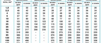
Knowing the strength of the current flowing in the circuit in amperes is important for calculating the cross-section of the wire used to lay the wiring and choosing a circuit breaker that protects the network from overloads. A cross-sectional value that is larger than necessary causes additional costs, while a smaller one will cause overheating of the electrical wiring, which can lead to melting of the cable insulation and a fire.
The correct choice of the machine is also important, since a large current reserve will be useless if the switch trips late and the equipment has time to fail, and too small a reserve will cause a very frequent emergency shutdown when the power consumption increases within acceptable limits.
According to Ohm's law, current can be calculated as the ratio of the voltage between two points to the resistance of this section of the circuit (the resistance of the wire itself). This parameter of the wire depends on its material, length and cross-section. When using standard materials (aluminum or copper), the only parameter that can be influenced is the cross-section of the conductor. And it depends on the expected current flow.
The current in a 220 V outlet usually does not exceed 6 amperes. This means that the total power of electrical appliances connected to the outlet should not exceed 1300 W. Otherwise, special wires with a larger cross-section must be laid.
Selection of electrical appliances
To find out which household appliance is suitable for electrical wiring at home, and for which it is better to use an industrial one, you need to pay attention to its power. This parameter is always written in the operating manual or technical specifications of the device.
You should be wary if the power indicated is more than 1.5 kW, since for such devices you need to use an increased cross-section of the power supply wires. Typically, household electrical appliances have less power.
An exception may be washing machines, electric stoves, and some types of vacuum cleaners. Houses with electric stoves always have separate wiring for them, but to power the washing machine it is better to install a separate wire of increased cross-section.
Next, you should decide on the choice of circuit breaker for groups of electrical consumers. It should be selected specifically for a group, in order to save space in the distribution panel, and to be more free in connecting devices to different sockets. Which groups are better to choose :
- Electric stove;
- Washing machine and water heater;
- Other sockets and lighting.
In homes with electric stoves, the stove will have the highest consumption. Its power is estimated at 10 kW, which with a standard voltage of 220 V means a current consumption of 45 A, cosφ here is 1. The electric stove requires a separate machine, so here it is selected for 50 amperes.
The washing machine also has high current consumption. A standard washing machine consumes 2.5 kW, which corresponds to 12.5 A. Despite the cosφ = 0.8 of the washing machine’s electric motor, it contains a large number of electronics, so for the calculation we take cosφ = 1. The water heater has an even greater power - up to 8 kW . If you intend to use them simultaneously with the washing machine, it is worth taking a machine with a higher amperage, since the total power of these two devices will be 10.5 kW, that is, you need another 50 A machine. It would be better to make two separate machines: 40 A for the water heater, and 15 A - for a washing machine.
The remaining sockets and lighting can be assigned to a separate group. Their total energy consumption is estimated at 1.5 kW, that is, a 10 A machine will be enough for the third group.
What formula is used to calculate the power of electric current?
This value is tied simultaneously to several physical parameters. Voltage is the work required to move 1 coulomb. Force means the number of coulombs that travel in 1 second. If you multiply the current by the voltage, it equals the amount of work done per second. To calculate the power of electric current, the formula is not difficult to derive.
She looks like
P = A / t = I x U,
the designations are as follows:
- P – current power in watts (W);
- A – its work on a given section of the circuit in joules (J);
- t – time during which the work was completed (in seconds);
- U – electrical voltage for a section of the circuit in volts (V);
- I – power in amperes (A).
This formula shows that the dependence of power on voltage and current is the same in this combination. One indicator can be higher and thereby compensate for the other to provide a powerful electric current. This feature ensures the transmission of electricity over long distances. Its transformation occurs through control transformers at substations.
Correct determination of power is critical to comply with safety regulations when operating the electrical network and avoid fires. This can happen if the wiring is incorrect. To measure, it is necessary to use special instruments, but this is not always possible.
Definition of power for alternating current:
- using an ammeter;
- according to the formula P= U x I using the values at the specified time;
- according to the formula P= U x I x cos φ, if there is a phase shift.
The symbol φ stands for power factor. When only light or heating devices are connected to the network, it is equal to 1; for more complex and powerful industrial-type equipment, the figure is 0.8. The formula for calculating power through resistance in a DC network is P = IU.