To organize a trouble-free in-house power supply, it is necessary to allocate separate branches. Each line must be equipped with its own protection device that protects the cable insulation from melting. However, not everyone knows which device to buy. Do you agree?
You will learn everything about choosing automatic machines based on load power from the article we presented. We will tell you how to determine the rating to find a switch of the required class. Taking into account our recommendations guarantees the purchase of the required devices that can eliminate dangerous situations during the operation of the wiring.
Automatic switches for household networks
Electricity supply organizations connect houses and apartments by carrying out work on connecting the cable to the switchboard. All installations of wiring in the premises are carried out by its owners or hired specialists.
To select a circuit breaker to protect each individual circuit, you need to know its rating, class and some other characteristics.
Basic parameters and classification
Household machines are installed at the entrance to a low-voltage electrical circuit and are designed to solve the following problems:
- manual or electronic activation or de-energization of an electrical circuit;
- circuit protection: current cut-off during minor long-term overload;
- Circuit protection: instantaneous shutdown of current in case of short circuit.
Each switch has a characteristic, expressed in amperes, which is called rated current (In) or "rating".
The essence of this value is easier to understand using the coefficient of excess of the nominal value:
K=I/In,
where I is the actual current strength.
- K < 1.13: tripping will not occur within 1 hour;
- K > 1.45: shutdown will occur within 1 hour.
These parameters are fixed in clause 8.6.2. GOST R 50345-2010. To find out how long it will take for a shutdown to occur at K>1.45, you need to use a graph reflecting the time-current characteristic of a specific machine model.
If the current exceeds the rated value of the switch by 2 times for a long time, the opening will occur within a period of 8 seconds to 4 minutes. The response speed depends on the model settings and the ambient temperature
Also, each type of circuit breaker has a current range (Ia) at which the instantaneous tripping mechanism is triggered:
- class "B": Ia = (3 * In .. 5 * In];
- class "C": Ia = (5 * In .. 10 * In];
- class "D": Ia = (10 * In .. 20 * In].
Type “B” devices are used mainly for lines that are of considerable length. In residential and office premises, class “C” circuit breakers are used, and devices marked “D” protect circuits where there is equipment with a high starting current coefficient.
The standard line of household machines includes devices with ratings of 6, 8, 10, 16, 20, 25, 32, 40, 50 and 63 A.
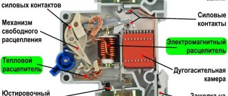
Structural design of releases
There are two types of releases in a modern circuit breaker: thermal and electromagnetic.
A bimetallic release has the shape of a plate created from two conductive metals with different thermal expansion. This design, when exceeding the nominal value for a long time, leads to heating of the part, its bending and the activation of the circuit breaking mechanism.
For some machines, you can use the adjusting screw to change the parameters of the current at which the shutdown occurs. In the past, this technique was often used to “fine-tune” a device, but this procedure requires in-depth specialized knowledge and several tests.
By rotating the adjusting screw (highlighted with a red rectangle) counterclockwise, you can achieve a longer response time for the thermal release
Now on the market you can find many models of standard ratings from different manufacturers, whose time-current characteristics are slightly different (but at the same time comply with regulatory requirements). Therefore, it is possible to select a machine with the required “factory” settings, which eliminates the risk of incorrect calibration.
The electromagnetic release prevents overheating of the line as a result of a short circuit. It reacts almost instantly, but the current value must be several times higher than the nominal value. Structurally, this part is a solenoid. The overcurrent generates a magnetic field that moves the core, breaking the circuit.
Compliance with selectivity principles
If there is a branched electrical circuit, it is possible to organize protection in such a way that in the event of a short circuit, only the branch on which the emergency situation occurs is disconnected. For this purpose, the principle of switch selectivity is used.
A visual diagram showing the principle of operation of a circuit breaker system with an implemented function of selectivity (selectivity) of operation when a short circuit occurs
To ensure selective shutdown, instantaneous cutoff circuit breakers are installed at the lower stages, breaking the circuit in 0.02 - 0.2 seconds. The switch located at a higher stage either has an operation delay of 0.25 - 0.6 s or is made according to a special “selective” circuit in accordance with the DIN VDE 0641-21 standard.
To ensure selective operation of the machines, it is better to use machines from one manufacturer. For switches of a single model range, there are selectivity tables that indicate possible combinations.
The simplest installation rules
The section of the circuit that needs to be protected by a switch can be single- or three-phase, have a neutral, as well as a PE (ground) wire. Therefore, the machines have from 1 to 4 poles, to which the conductor is connected. When conditions for tripping are created, all contacts are disconnected simultaneously.
The machines in the panel are mounted on a specially designated DIN rail. It provides compact and safe connection, as well as convenient access to the switch
The machines are installed as follows:
- single-pole per phase;
- bipolar for phase and neutral;
- three-pole for 3 phases;
- four-pole for 3 phases and neutral.
However, it is prohibited to do the following:
- install single-pole circuit breakers to neutral;
- insert PE wire into the machine;
- install three single-pole ones instead of one three-pole circuit breaker, if at least one three-phase consumer is connected to the circuit.
All these requirements are specified in the PUE and must be followed.
In every house or room to which electricity is supplied, an introductory machine is installed. Its nominal value is determined by the supplier and this value is specified in the electricity connection agreement. The purpose of such a switch is to protect the area from the transformer to the consumer.
After the input circuit breaker, a meter (single- or three-phase) and a residual current device are connected to the line, the functions of which differ from the operation of an automatic and differential switch.
If the room is wired into several circuits, then each of them is protected by a separate circuit breaker, the power of which is indicated in the marking. Their ratings and classes are determined by the owner of the premises, taking into account the existing wiring or power of connected devices.
The electricity meter and circuit breakers are installed in a distribution board that meets all safety requirements and can easily be integrated into the interior of the room
When choosing a location for the distribution board, it must be remembered that the properties of the thermal release are affected by air temperature. Therefore, it is advisable to place the rail with machines inside the room itself.
How to connect AV according to the diagram
We offer schematic examples of connecting AV in a distribution panel.
Please note that each circuit diagram for connecting machines in the panel involves division into groups according to the selectivity of supply. Modular devices are divided into socket groups and lighting lines; sometimes protection for particularly powerful consumers is provided separately. Ideally, for safety and beauty, I install plugs on the sides of the bus so that the contacts are covered with insulation. Limiters on a DIN rail will help to visually separate groups of machines and ensure heat dissipation, since the devices heat up during operation and close proximity, and the limiters will also reliably fix the devices themselves. A separate group, as a rule, is isolated with a comb and only one AB from the group is supplied with power.
Calculation of the required denomination
The main protective function of the circuit breaker extends to the wiring, so the rating is selected based on the cable cross-section. In this case, the entire circuit must ensure the normal operation of the devices connected to it. Calculating system parameters is simple, but many nuances must be taken into account in order to avoid errors and problems.
Determination of the total power of consumers
One of the main parameters of the electrical circuit is the maximum possible power of the electricity consumers connected to it. When calculating this indicator, you cannot simply summarize the passport data of devices.
Active and nominal component
For any device powered by electricity, the manufacturer is required to indicate the active power (P). This value determines the amount of energy that will be irrevocably converted as a result of the operation of the device and for which the user will pay on the meter.
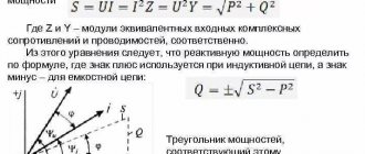
But for devices with capacitors or an inductor, there is another power with a non-zero value, which is called reactive (Q). It reaches the device and returns back almost instantly.
The reactive component does not participate in the calculation of used electricity, but together with the active component it forms the so-called “total” or “nominal” power (S), which puts a load on the circuit.
cos(f) – parameter with which you can determine the total (nominal) power from the active (consumed) power. If it is not equal to one, then it is indicated in the technical documentation for the electrical device
It is necessary to calculate the contribution of an individual device to the total load on the current-carrying conductors and the circuit breaker based on its total power: S = P / cos(f).
Increased starting currents
The next feature of some types of household appliances is the presence of transformers, electric motors or compressors. Such devices consume inrush (starting) current when starting up.
Its value can be several times higher than standard values, but the operating time at increased power is short and usually ranges from 0.1 to 3 seconds. Such a short-term surge will not trigger the thermal release, but the electromagnetic component of the switch, which is responsible for the short-circuit overcurrent, may react.
This situation is especially relevant for dedicated lines to which equipment such as woodworking machines are connected. In this case, you need to calculate the amperage and, perhaps, it makes sense to use a class “D” machine.
Taking into account the demand coefficient
For circuits that have a large amount of equipment connected and no device that consumes the largest portion of the current, use the demand factor (ks). The point of using it is that all devices will not work at the same time, so summing up the rated powers will lead to an overestimated figure.
The demand coefficient for groups of electricity consumers is established in clause 7 of SP 256.1325800.2016. You can also rely on these indicators when independently calculating maximum power.
This coefficient can take a value equal to or less than one. The calculated power (Pr) of each device is calculated using the formula:
Pr = ks * S
The total rated power of all devices is used to calculate the circuit parameters. The use of the demand coefficient is advisable for office and small retail premises with a large number of computers, office equipment and other equipment powered from one circuit.
For lines with a small number of consumers, this coefficient is not used in its pure form. Those devices that are unlikely to be turned on simultaneously with more energy-consuming devices are removed from the power calculation.
So, for example, there is little chance of working in a living room with an iron and a vacuum cleaner at the same time. And for workshops with a small number of personnel, only 2-4 of the most powerful power tools are taken into account.
Current calculation
The machine is selected based on the maximum current value allowed in the circuit section. It is necessary to obtain this indicator, knowing the total power of electrical consumers and the voltage in the network.
According to GOST 29322-2014, from October 2015, the voltage value should be equal to 230 V for a regular network and 400 V for a three-phase network. However, in most cases, the old parameters are still in effect: 220 and 380 V, respectively. Therefore, for accurate calculations, it is necessary to take measurements using a voltmeter.
You can measure the voltage in your home network using a voltmeter or multimeter. To do this, just plug its contacts into a power outlet.
Another problem, especially relevant for electrical wiring in the private sector, is the provision of electricity with insufficient voltage. Measurements at such problematic objects may show values outside the range defined by GOST.
Moreover, depending on the level of electricity consumption of your neighbors, the voltage value can vary greatly within a short time.
This creates a problem not only for the functioning of the devices, but also for calculating the current strength. When the voltage drops, some devices simply lose power, and some that have an input stabilizer increase their electricity consumption.
It is difficult to carry out qualitative calculations of the required circuit parameters under such conditions. Therefore, you will either have to lay cables with a deliberately large cross-section (which is expensive), or solve the problem by installing an input stabilizer or connecting the house to another line.
The stabilizer is installed next to the switchboard. It often happens that this is the only way to obtain standard voltage values in the house
After the total power of electrical appliances (S) has been found and the voltage value (U) has been determined, the current strength (I) is calculated using formulas that are a consequence of Ohm’s law:
If = S / Uf for single-phase network
Il = S / (1.73 * Ul) for three-phase network
Here the index “f” means phase parameters, and “l” means linear.
Most three-phase devices use the “star” connection type, and it is also according to this circuit that the transformer operates, delivering current to the consumer. With a symmetrical load, the linear and phase forces will be identical (Il = If), and the voltage is calculated using the formula:
Ul = 1.73 * Uf
Nuances of selecting cable cross-section
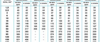
The quality and parameters of wires and cables are regulated by GOST 31996-2012. According to this document, specifications are developed for manufactured products, where a certain range of values of basic characteristics is allowed. The manufacturer is obliged to provide a table of correspondence between the cross-section of the cores and the maximum safe current.
The maximum permissible current depends on the cross-section of the wires and the installation method. They can be laid hidden (in the wall) or open (in a pipe or box) way
It is necessary to select a cable in such a way as to ensure the safe flow of current corresponding to the calculated total power of electrical appliances. According to the PUE (electrical installation rules), the minimum design cross-section of wires used in residential premises must be at least 1.5 mm2.
Standard sizes have the following values: 1.5; 2.5; 4; 6 and 10 mm2.
Sometimes there is a reason to use wires with a cross-section one step larger than the minimum allowable. In this case, it is possible to connect additional devices or replace existing ones with more powerful ones without expensive and time-consuming work on laying new cables.
Calculation of machine parameters
For any circuit the following inequality must be satisfied:
In <= Ip / 1.45
Here In is the rated current of the machine, and Ip is the permissible current for wiring. This rule ensures guaranteed release when the permissible load is exceeded for a long time.
The inequality “In <= Ip / 1.45” is the main condition when completing the “machine-cable” pair. Failure to comply with this rule may result in a fire in the wiring.
The rating of the machine can be calculated both by the total load and by the cross-section of the wires of the already installed wiring. Let's say that there is a diagram for connecting electrical appliances, but the wiring has not yet been laid.
In this case, the sequence of actions is as follows:
- Calculation of the total current strength of electrical appliances connected to the network.
- Select a machine with a denomination not less than the calculated value.
- Selection of cable cross-section according to the machine's rating.
Example:
- S = 4 kW; I = 4000 / 220 = 18 A;
- In = 20 A;
- Ip >= In * 1.45 = 29 A; D = 4 mm2.
If the wiring has already been laid, then the sequence of actions is different:
- Determination of the permissible current for a known cross-section and method of wiring according to the table provided by the manufacturer.
- Selection of circuit breaker.
- Calculation of the power of connected devices. Equipping a group of devices in such a way that the total load on the circuit is less than the nominal value.
Example. Let two single-core cables be laid openly, D = 6 mm2, then:
- IP = 46 A;
- In <= Ip / 1.45 = 32 A;
- S = In * 220 = 7.0 kW.
In point 2 of the last example there is a slight acceptable approximation. The exact value In = Ip / 1.45 = 31.7 A is rounded to 32 A.
Choice between several denominations
Sometimes a situation arises when you can select several machines with different ratings to protect the circuit. For example, with a total power of electrical appliances of 4 kW (18 A), wiring with a copper core cross-section of 4 mm2 was chosen with a reserve. For this combination, you can install 20 and 25 A switches.
If the electrical wiring diagram assumes the presence of multi-tier protection, then you need to select circuit breakers so that the value of the rating of the higher one (in the figure on the right - 25 A) is greater than that of switches of lower levels
The advantage of choosing a switch with the highest rating is the ability to connect additional devices without changing the circuit elements. Most often this is what they do.
The choice of a machine with a lower rating is supported by the fact that its thermal release will respond faster to an increased current. The fact is that some devices may have a malfunction, which will lead to an increase in energy consumption, but not to the point of a short circuit.
For example, a failure of a washing machine motor bearing will lead to a sharp increase in current in the winding. If the machine quickly reacts to exceeding the permitted values and switches off, the motor will not burn out.
How to avoid major wiring mistakes
It is very important to connect the circuit breakers in the panel yourself with an understanding of the functioning of the wires. How to avoid the most common mistakes for reliable contacts? Let's start in order.
- To get high-quality contact, you need to strip the core, that is, remove part of the insulation from the wire. If the insulation is not sufficiently stripped, it will fall under the contact clamp, and this can lead to melting of the wiring, the protection device itself, and even a risk of fire. Monitor and check the degree of tightening of the conductor in the socket.
- Wires of unequal cross-sections cannot be connected to the same terminal. The comb bus does an excellent job of connecting a group of machines to one power wire. But when an electrician prefers a homemade jumper made from cable cores, a safe result will only be achieved when using wires of the same cross-section. Otherwise, when the contacts are tightened, the clamp will be uneven (the thin core will be compressed worse, which will lead to loosening of the contact, heating, sparking and melting of the insulation), in addition, the machine platform will be deformed towards a smaller cross-section.
- If you connect a cable with a monolithic core to the machine, bend its end with a hook. This activity can be called creating a U-shaped bend and thanks to this simple step you will increase the area of contact of the wire with the surface of the clamp. This is an additional plus to the reliability of contacts.
- When connecting a multi-core flexible wire, it must be terminated before connecting to the AB. We recommend using NShVI (insulated pin sleeve lugs) or NShV lugs for termination. Double NShVI-2 is used to connect a pair of stranded wires; this is a convenient way to form jumpers for groups of circuit breakers.
- We strongly do not recommend soldering or tinning the ends of multi-core wires, since this is a sure way to “spreading” of the connection over time, overheating and melting of the solder, weakening and burnout of the contact.
Conclusions and useful video on the topic
Design of a circuit breaker and its classification. The concept of time-current characteristics and selection of rating according to the cable cross-section:
Calculation of the power of devices and selection of a machine using the provisions of the PUE:
The choice of circuit breaker must be taken responsibly, since the safety of the electrical system at home depends on it. With all the many input parameters and calculation nuances, it is necessary to remember that the main protective function of the machine applies to the wiring.
Please write comments, ask questions, and post photos related to the topic of the article in the block below. Share useful information that may be useful to site visitors. Tell us about your own experience in choosing circuit breakers to protect country or home electrical wiring.
The meaning and main tasks of selective protection
Safe operation and stable operation of electrical installations are the tasks assigned to selective protection. It instantly calculates and cuts off the damaged area without interrupting the power supply to healthy areas. Selectivity reduces the load on the installation and reduces the consequences of a short circuit.
With well-functioning operation of circuit breakers, requests for uninterrupted power supply and, as a consequence, the technological process are satisfied to the maximum.
When the automatic equipment that carries out the opening becomes faulty as a result of a short circuit, thanks to selectivity, consumers will receive normal power.
The rule stating that the amount of current passing through all distribution switches installed behind the input circuit breaker is less than the designated current of the latter is the basis of selective protection.
In total, these denominations may be greater, but each individual denomination must be at least one step lower than the introductory denomination. So, if a 50-amp circuit breaker is installed at the input, then a switch with a current rating of 40 A is installed next to it.
Using the lever, you can turn on or off the current input to the terminals. Contacts are connected to the terminals and fixed. The moving contact with the spring serves for quick opening, and the circuit is connected to it through a fixed contact.
Decoupling, if the current exceeds its threshold value, occurs due to heating and bending of the bimetallic plate, as well as the solenoid.
Triggering currents are adjusted using an adjusting screw. In order to prevent the occurrence of an electric arc during contact opening, an element such as an arc extinguishing grid was introduced into the circuit. There is a latch to secure the machine body.
Selectivity, as a feature of relay protection, is the ability to detect a faulty system unit and cut it off from the active part of the EPS.
The selectivity of automata is their ability to work alternately. If this principle is violated, both circuit breakers and electrical wiring will heat up.
As a result, a short circuit on the line, burnout of fusible contacts and insulation may occur. All this will lead to failure of electrical appliances and fire.
Let's say there is an emergency on a long power line. According to the main rule of selectivity, the machine closest to the damage site is triggered first.
If a short circuit occurs in an outlet in an ordinary apartment, the protection of the line of which this outlet is part should be activated on the panel. If this does not happen, it is the turn of the circuit breaker on the panel, and only behind it - the input one.
General concept of selectivity
To protect electrical networks from overloads and short circuits, circuit breakers are used in the relay protection system. In an emergency, they completely disconnect consumers, which is not always convenient. In this regard, selective protection schemes have been developed, the principle of which is to disconnect not the entire line, but only the emergency section. The group circuit breaker remains in the on state.
Read also: Diagram of DC welding machine VD 305
It follows that selectivity is considered to be a certain selection of machines for one system, designed to ensure the shutdown of only a specific emergency section. That is, the protective device that is responsible for this section is triggered, and at this time the other machines operate in normal mode. By means of selectivity, the operation of protective equipment installed in series is coordinated. If a short circuit or overload occurs, only the faulty part of the electrical installation is switched off.
The choice of circuit breakers, including those for protection with absolute selectivity, depends on their rating and operation characteristics, designated as B, C and D. The system must be designed in such a way that operations occur at the right time at different short-circuit currents.
Modular circuit breakers differ in current by different classes of current limitation, which characterize the response time of electromagnetic releases and their own selectivity. However, speed is not always decisive, therefore, in selective systems, group automatic machines are installed that operate more slowly than devices on outgoing lines. This makes it possible to prevent simultaneous operation of the main device and the machine with a lower current limit.
Selectivity map and rules for its creation
The time-current characteristics of all devices included in the electrical network circuit are depicted on a selectivity map. The purpose of its compilation is to ensure maximum protection for the machines. The basis of switch protection is the principle by which switches are connected one after another strictly in series.
There are a number of rules that are required when creating a selectivity map:
- Installations must have one voltage source.
- All important design points should be clearly visible. Taking this requirement into account, it is necessary to choose a scale.
- The map indicates the protective properties, minimum, maximum short circuit parameters at points in the system.
Often design standards are violated, and selectivity maps are missing in projects. This may lead to interruptions in power supply to consumers.
The map gives a complete picture of the coordination of settings. It provides an opportunity to compare the operation of machines based on such characteristics as selectivity.
Time-current varieties of axes are the basis not only for constructing selectivity maps for current protection in the form of circuit breakers, but also for its other types: fuses, relays. Typically one card contains 2-3 AB characteristics. The abscissa axis shows the current value in kV, and the ordinate axis shows the time in seconds.
Functions and tasks of selectivity
The main task of selective protection is to ensure stable operation and safe operation of electrical installations. In the event of an emergency, the damaged area is identified almost instantly and is immediately switched off without disrupting the operation of healthy areas. Due to selectivity, the load on electrical installations is significantly reduced, and the negative consequences of a short circuit are reduced.
The precise and coordinated operation of automatic protective devices maximally meets the requirements for uninterrupted power supply. As a result, the selectivity of the circuit breaker maintains the continuity of all technological processes involving electrical installations. Disabled areas do not in any way affect their stable operation.
The basic rule of selective protection devices involves installing circuit breakers with a rated current lower than that of the input device. In total, they can exceed the rating of a group machine, but individually each of them must be at least one step lower. That is, when installing a 50 A input device, the next device on the line will have a rating of no higher than 40 A. The machine closest to the fault location is always triggered first.
The selectivity of the machines is ensured by their design. Turning the power on and off is done using a special lever. Fixed contacts are connected to terminals, to which, in turn, conductors are connected. Quick opening is carried out using a moving contact connected to a spring. Disconnection is ensured by a bimetallic plate, which bends after heating if the current exceeds its maximum permissible value.
There is an adjusting screw to adjust the operating currents. Together, all elements contribute to quickly identifying the faulty area and cutting it off from the working parts.
The basic principle of selectivity is considered to be the sequential operation of protective equipment. In case of deviations from the norms, overheating will occur not only of the machines, but also of the electrical wiring. As a result, emergency situations arise with serious negative consequences.
Absolute and relative selectivity of protection
The concept of selectivity is defined by GOSTotm IEC 60947-1-2014 . There are two types of selectivity - absolute and relative. If the protection is coordinated in such a way that it operates exclusively within the protected area, then this indicates its absolute selectivity.
In these circumstances, the maximum selectivity current becomes the same as the maximum breaking capacity of the circuit breaker located below.
Triggering as a backup, when a shutdown has not occurred in the problem area, is called relatively selective protection. In this case, the switches located above are turned off.
If the specified current value of the circuit breaker is exceeded, i.e. in the absence of large overloads, selective protection operates almost without fail. It is much more difficult to achieve this with short circuits.
Enterprises post data on manufactured products on the device body and on their websites. It is important to read the markings of machines correctly - bundles of switches are formed only according to the tables of one specific manufacturer. It should be borne in mind that groups organized on a relative basis have a large number of functions.
To check the selectivity between the machine above and below, find the intersection of the vertical and horizontal. Ensuring selectivity is a very important task when feeding consumers belonging to a special category.
In its absence, the production process may stop, lines may be damaged, air conditioning systems, smoke removal systems, and others will be turned off.