Primary requirements
Most of the relevant recommendations and rules regulate the design and placement of such a component of the grounding system. Requirements that an artificial grounding system must meet:
- For arid areas, there is a separate technology for grounding using reinforced concrete structures.
- The artificial grounding conductor cannot be painted. This is explained by the fact that any coloring acts as an insulator. The insulation will prevent current from flowing into the soil. The artificial grounding conductor must have a natural color.
- Welding seams (conductor connections) must be painted. Painted with bitumen paint, premature destruction of the connecting elements is prevented.
- Non-standard (reduced) electrode values are used exclusively when installing temporary electrical installations.
The optimal choice of grounding material is considered to be round reinforcement. Justification for this priority:
- Minimum metal consumption. Consequently, the cost of the grounding device is reduced.
- The corrosion resistance of such an electrode is significantly higher than that of its analogues.
- Ease of installation.
In addition to the profile requirements, there is a recommended standardization of the parameters (dimensions) of the material used to create an artificial grounding element.
Advantages of GAZ-M anode grounding electrodes
- deep grounding allows joint protection against corrosion of the entire complex of underground metal structures on the territory of an industrial facility or city;
- to place deep grounding, tens of times less area is required than for underground grounding;
- the potential gradient on the earth's surface, with the correct choice of design and installation location for deep grounding, has relatively low values;
- the manifestation of the anode influence of a deep grounding electrode is many times less than that of a subsurface one of the same power, which allows it to be located in small free areas in an area with a highly branched and complex network of underground structures;
- deep anodic grounding ensures a more rational use of current, since it flows mainly from below to the part of the protected structure that is most susceptible to corrosion;
- the current shielding effect is manifested to a much lesser extent;
- the resistance to spreading of the deep anode ground electrode does not depend on seasonal fluctuations in temperature and moisture content in the upper layers of the earth.
The GAZ-M grounding conductor has been issued a certificate from the State Standard of Russia, confirming that this grounding conductor complies with the standards of the Russian Federation.
Device and principle of operation
This method of anti-corrosion protection is used not only to protect objects made of steel, but also equipment made of materials such as zinc, copper, aluminum, tin, lead, titanium, nickel and their alloys. The object to be protected becomes the cathode when connected to the negative pole of the power source, and the anode connected to the positive pole dissolves and is destroyed during the protection process, keeping the object intact.
The degree of dissolution of the anode grounding electrode depends on the parameters of its environment, on the density of the flowing current and on the material of the grounding electrode itself. Therefore, the electrodes are made of a corrosion-resistant iron-silicon alloy - ferrosilide ChS-15 (GOST 7769-86) of cylindrical shape. The electrode is firmly installed in the ground electrode housing and is reliably insulated with epoxy compound. In addition, the grounding switch has a contact assembly, a sealed coupling for connection to the main cable line of the cathodic protection station and a special wire with a copper core with reinforced insulation.
History of the creation of deep anode grounding electrodes
To prevent metal corrosion, UKZ - cathodic protection installations are used. The protected object is negatively polarized, it is assigned the role of a cathode, and a special ground electrode is used as an anode. As a result of electrolysis, reduction processes occur on the surface of the object, corrosion slows down significantly, and the anode is gradually destroyed (therefore it is called a sacrificial electrode).
But in dense urban areas it is difficult to place the anode grounding electrode horizontally. In addition, with such an arrangement there is a danger of a negative impact on other objects. Therefore, the American scientist Robert Kuhn proposed installing ground electrodes at great depths and vertically. The idea was first implemented in 1952 in New Orleans, where the anode was lowered into a well 90 m deep.
Later it turned out that a deep anode grounding system is the best option not only for cities, but also in cases where the upper layers of soil are characterized by high resistivity, and with distance from the surface it decreases. This technology is not only suitable for rocky areas and wetlands.
Switching electrical devices
Electrical switching devices are widely used in various industries. It is difficult to imagine how the various operating and maintenance tasks associated with electrical equipment would be accomplished without this functional device.
An electrical switching device is used to disconnect and close an electrical circuit using a contact group. Simply put, such a device can be called a switch.
The main types of devices presented include: switches, switches, contactors, relays. Despite the fact that these devices have almost the same operating principle, they all have a number of differences from each other.
Let's consider each type of device separately.
A switch is one of the simplest switching devices. The device is operated manually using a handle. This type of device is designed for high current values.
Switches have different modifications. In industrial applications, the most common types of such devices are oil switches. Such switches are designed for voltages up to 220 kV.
Oil, in this case, serves to suppress/quench the electric arc passing through it. Air and electric gas circuit breakers deserve special attention.
Extinguishing the arc, that is, stopping the supply of electric current, occurs due to the supply of a jet of compressed air or electronegative gas.
A radically new method of opening a current-carrying line is embodied in electromagnetic switches.
The principle of operation of such a device is as follows: the electric arc burns under normal conditions at atmospheric pressure - the circuit is turned on.
As soon as the circuit needs to be opened, a strong magnetic field is applied towards the arc. Due to the influence of the magnetic field, the arc begins to stretch and ultimately splits, thereby opening the conductive line.
The relay is designed to open and close an electrical circuit. The main characteristic property of this switching device is a fundamentally new way of operating a contact pair.
An electromagnetic relay, as in a contactor, under the influence of an electric current, sets in motion the electromagnet core with contacts installed on it, which leads to the closure of the circuit. The method of influencing the relay contact pair can be not only electrical, but also thermal or acoustic.
Contactors are a type of electromagnetic relay. The main purpose is to turn on and off the current-carrying line of power electrical circuits.
Contactors can be used in both alternating and direct electric current circuits. The operating principle of the contactor is based on the electromagnetic effect.
The core of the contactor electromagnet, under the influence of electric current, carries with it a moving contact, which, due to such movement, is pressed against the stationary contact and the circuit is closed.
As soon as the current supply is stopped, the core returns to its original position and the contacts open.
Ground loop materials
The grounding loop must have high mechanical strength, low electrical resistance and the ability to be connected reliably. In addition, an important role when choosing a material is played by its cost.
Pin parameters and materials
Electrodes or pins are usually made of steel profile. This material is attractive due to the possibility of deepening the rods by simply driving it in. At the same time, its electrical resistance fully satisfies the requirements with a sufficient cross section. Pins can be made from the following materials:
- Bar. The most common option is a rod with a diameter of 16-18 mm. It is not recommended to use fittings, because it is heated, which leads to an increase in resistivity. In addition, the corrugated surface leads to irrational use of the rod cross-section.
- Corner. The most commonly used corner is 50x50 mm in size with a wall thickness of 4-5 mm. The bottom is pointed to make driving easier.
- Pipe with a diameter of more than 50 mm with a wall thickness of 4-5 mm. Thick-walled pipes are recommended for hard soils and regions with frequent droughts. Holes are drilled at the bottom of such a pin. When the soil dries out, salt water is poured into the pipe, which increases the dispersive ability of the soil.
What to make metal connection from
Electrodes driven into the ground are connected to each other by metal bonding. It can be made from the following materials:
- Copper busbar or wire with a cross-section of at least 10 mm2.
- Aluminum strip or wire with a cross-section of at least 16 mm2.
- Steel strip with a cross-section of at least 48 sq. mm.
The most commonly used steel strip measuring (25-30)x5 mm. Its main advantage is the possibility of reliable welding with electrodes. When a conductor made of non-ferrous metals is used as a connection, bolts are welded to the pins on which the tires are secured.
General concept of grounding
Grounding (Pe from protection earth) is understood as the intentional connection of electrical installations or parts thereof to a conductor buried in the ground. For the system to perform its functions, it must have low resistance.
Purpose
The soil is capable of absorbing electrical charge like a capacitor with infinite capacity. This property is used to solve a number of problems.
Grounding ensures electrical contact between the electrical installation and the ground.
Areas of use
According to the method of use, grounding is divided into 2 types:
- Working. Acting as a neutral, it ensures the functioning of powerful electrical installations - transformers, generators, arresters, arc extinguishers, etc. This type also includes Pe-circuits of lightning rods and surge protection devices.
- Protective. Protects users from electric shock.
The second type comes into effect in emergency situations, when a phase is shorted to non-current-carrying metal parts of the electrical installation. Further we will talk only about this type of grounding.
Principle of operation
If you understand the structure of this system, then you can understand that electrolytic grounding will work based on the occurrence of chemical reactions. Grounding can work according to the following principle:
- The mixture will need to be poured into the full electrode. It will absorb moisture from the environment through a special hole.
- Now the water will react with salt and as a result, an electrolyte will be formed, which seeps into the soil. Thanks to this kind of work, the soil will become electrically conductive and not prone to freezing.
This reaction will occur regardless of the temperature present in the environment.
Operating conditions of ground electrodes
Grounding switches must be used in the conditions for which they are intended, depending on the type used. Maintenance and repairs must be carried out in accordance with the requirements of the manufacturer's operating manual and regulatory documents.
The specified work must be carried out with the involvement of trained and certified personnel, in compliance with the provided permit system.
Before connecting the equipment to the network, the following checks must be performed:
- cleanliness and integrity of insulators;
- tightness of threaded connections;
- presence of lubricant in the relevant components;
- sufficient contact pressure.
The proper operation of the device is first checked by performing several control turns on and off.
Maintenance involves regular inspections of its components, lubrication of rubbing parts, monitoring the condition of contacts, cleaning contacts and other elements. The frequency of maintenance is determined by the conditions and intensity of operation, but must be carried out at least once a year.
How to calculate the parameters of the main grounding elements
Based on the results of such calculations, a drawing of the grounding device of the facility is designed.
Important! The device, mounted in accordance with all the calculated data of the grounding scheme, allows you to achieve maximum operational efficiency of the entire protective grounding complex. The basis of calculations is the permissible limits of step and touch voltage
Based on them, the configuration (size, number) of grounding conductors and the principle of their placement are calculated
The basis of the calculations is the permissible limits of step and touch voltage. Based on them, the configuration (size, number) of grounding conductors and the principle of their placement are calculated.
Calculations are performed based on the following data:
- Description of the characteristics of specific electrical equipment: installation type; main structural elements of the device; operating voltage; Possible options that allow grounding of neutrals of both transforming and generating devices.
- Grounding configuration. Such data is necessary to determine the optimal immersion depth of the electrodes.
- Information about studies conducted to measure soil resistivity in a specific area. Additionally, the climatic information of the zone in which the system is being installed is taken into account.
- Information on suitable natural earthing elements that can be used in your work. Data are needed on the real values of current spreading in these objects. They can be obtained by special measurements.
- The result of a standard calculation of the exact indicators of the estimated current short circuit on the soil.
- Calculated values of regulatory standardization of permissible voltage characteristics according to PUE.
- Indicators of resistance to seasonal freezing of the soil layer during the period of drying and freezing. Taking into account such values is necessary for calculating grounding elements that are located in a homogeneous environment. Special standardized coefficients are applied.
- If it is necessary to install a complex group of grounding conductors, consisting of several elements, it is necessary to know all the potentials that will be induced on the mounted electrodes. To do this, we need data on the resistance values of all soil layers.
Important! If the system is placed in two layers of soil, the resistance value of each of them is taken into account. This is necessary to determine accurate data on the power parameters of the top soil layer
The best anode grounding models
Currently, there are a large number of different models of anode grounding on the market, both for surface placement and for installation at considerable depth. In each specific case of installation of this equipment, the number of necessary elements must be correctly calculated and displayed in the plan.
An important condition for the effectiveness of protection is the choice of a high-quality device and a reliable power station. As a rule, such devices are sold in a set consisting of 10 - 20 grounding conductors and one power source. Of the surface grounding devices, the following models are most often used to protect underground metal objects:
- “Mendeleevets”-MM - this type of surface grounding conductor allows you to effectively prevent the destruction of underground communications. “Mendeleevets”-MM is used primarily in the field of oil and gas communications, but can also be used for other underground objects that may be subject to corrosion. The rate of anodic dissolution of the electrode is 300 g/year, therefore, with a mass of 43 kg, the protection can be effectively used for at least 100 years.
- "Mendeleevets"-MTP is a magnetite surface grounding conductor designed to protect main pipelines. A special feature of this model is the ability to install electrodes to protect port facilities. The installed ground electrodes do an excellent job of protecting metal structures from the occurrence of corrosion processes in a highly aggressive environment. “Mendeleevets”-MTP is perfectly sealed at the point where the power wire is connected. Power is supplied by a working electrical station, which is included in the kit of this protective device.
Among the deep models, the following devices are most widely used:
- "GAZ-M" is a deep grounding electrode of excellent quality. This device does an excellent job of protecting underground metal objects in cases where installing a cheaper surface protection option is not possible. The working life of the ground electrode is at least 30 years, and the maximum operating current is 10 A.
- "Mendeleevets"-MRKG is a low-soluble deep grounding agent, which is used mainly in soil with high resistivity.
This device can be placed in one well, in quantities of up to 24 pcs. which allows you to protect underground objects as effectively as possible.
The minimum service life of this device is at least 30 years, provided that the installation of the anode grounding electrode was carried out in accordance with all the rules.
Operating principles of anode grounding electrodes
Around the middle of the 20th century, scientists realized that it was not possible to overcome the development of corrosion of underground metal structures using protective coatings alone. Due to the heterogeneous structure, high humidity and acidity of the soil, areas with opposite electrode potentials appear on the metal surface. As a result, galvanic corrosion formations occur.
Corrosive destruction of metal is additionally provoked by the influence of stray currents. Such currents appear from time to time in the soil on the surface of which electric vehicles pass, electrical substations, cell towers, etc. are located.
To avoid corrosion processes, cathodic protection installations are used. The object finds itself in conditions of negative polarization, where it acts as a cathode. The role of the anode is given to a special grounding device.
Being in an electrolyte environment, different types of metals have different electrode potentials. If you run a minus in a steel pipeline from a constant source of electricity, and install an electrode made of zinc, aluminum or magnesium with a plus connected to it next to the pipe, the non-ferrous metal will act as an anode. The electrolysis reaction on the metal surface triggers recovery processes, rusting becomes less intense, and the anode is destroyed. Such anodes are called sacrificial electrodes.
According to this scheme, all kinds of metal structures located underground, including containers, columns, and pipelines, are protected. To organize effective protection, it is important not only to choose the right anode grounding conductor, but also to carry out the installation work correctly.
In dense urban areas, it is often impossible to place the anode ground electrode horizontally. There is a possibility of its negative impact on surrounding objects. In this regard, American scientists have put forward a proposal for the possibility of installing grounding devices at great depths in a vertical position. The first embodiment of the idea was released in 1952 in the USA. The anode grounding electrode was installed at a depth of 90 meters.
Subsequently, it was proven in practice that deep ground electrodes are suitable not only for cities, but also for use in areas where the upper layers of soil have high resistivity. Moving away from the surface, the resistance should decrease. Deep grounding technology is not applicable only to rocks and wetlands.
Classification
When studying the topic of anode grounding electrodes, it is important to understand their features and classification. Conventionally, products are divided according to several criteria
By location
Anode grounding electrodes differ in position relative to the protected object or working element.
Depending on their location relative to the protected object, they are:
- Deep - several electrodes connected by cables. They are located at a depth of about 40 m and are coated with a coke-mineral composition, which significantly increases the weight of the product. Drilling rigs are used for installation, which makes the work more expensive. Despite the high costs, deep anode grounding electrodes have an increased range of action, and their resistance does not depend on the time of year. The average service life is about 30 years.
- Surface - perform the same functions, but are installed at the same level with the protected products. They are compact and have a relatively short range of action. It has the form of an electrode made of zinc, magnesium or iron-silicon alloy. The latter option is used most often due to its more affordable price and high efficiency. They have the form of a round rod with points for connecting to cable products.
- Extended - anode grounding electrodes, made in the form of a current-carrying cable with a wire electrode located around it. A coating from a group of metal oxides is applied to the surface of the latter. The structure is packaged in coke breeze, which is used as a grounding conductor. Extended grounding conductors are used in any type of soil and are placed in the same pit with the metal object being protected.
- Internal - anodic grounding conductors used to protect metal containers, pipes and other products. Their peculiarity is that they are mounted vertically or horizontally inside the protected object. Structurally, they have the form of an electrode equipped with a corrosion-resistant cable and placed in a special dielectric cylindrical screen. Installation of grounding conductors is carried out manually without the use of additional devices and equipment.
According to their location relative to the working element, anode grounding electrodes can be placed:
- vertically;
- horizontally;
- inclined;
- in the combined version - a combination of all the types discussed above.
By material
When choosing anode grounding conductors, it is necessary to take into account the material from which the working element is made.
There are several solutions available here:
- cast iron;
- steel;
- graphite and plastic;
- iron and silicon;
- composite polymer;
- conductive elastomer;
- combined valve metal, etc.
Conventionally, materials can be metallic or non-metallic, but we will dwell on this issue below.
According to cross-sectional shape
In the manufacture of an anode grounding electrode, different forms of electrodes can be used.
Available options:
- rectangle;
- cylinder;
- sphere;
- screw;
- corner;
- flat panel;
- hollow tube;
- wire;
- kernel;
- mesh with small cells.
Depending on the shape of the product, installation approaches and characteristics of the finished structure change, so these issues must be taken into account during design and installation.
According to the nature of backfilling of the anode region
During installation, approaches to filling the space near the anode filler may vary.
The following backfill options are possible:
- special activator to reduce spreading resistance;
- coal and graphite;
- coke-mineral composition;
- conductive backfill;
- shungite;
- priming.
When choosing backfill, the type of object being protected and its features are taken into account.
By distance
Depending on the situation, the anode grounding electrode can be installed at different distances from the protected object.
Available options:
- remote;
- intimates;
- distributed.
By design
When choosing a product, it is important to take into account its design features. Main types:
Main types:
- extended;
- sparingly soluble;
- distributed;
- concentrated (for example, piles).
In practice, other types of anode grounding electrodes can be used. The choice of type and features is made during design.
According to climatic version
At the project creation stage, it is necessary to take into account the climate in which the anode grounding system will be installed.
Taking this fact into account, one of the following options is selected:
- for use on land - GOST-15150;
- operation at sea - category B (5).
The climatic features of products are specified in technical specifications and standards.
Design and installation features
The design and installation of a deep grounding device is carried out in accordance with certain rules:
- The electrodes included in the garland are installed exclusively below the soil freezing level. This condition should be observed especially clearly in regions with permafrost soils.
- If the current at the cathode station exceeds 25 Amperes, it will be necessary to install a perforated tube on the garland to remove gases released during operation of the equipment. Otherwise, the gas shell that appears near the anode increases the resistance and reduces the range of the system.
- To extend the service life of the electrodes, the well is filled not with earth, but with coke crumbs.
1.7.93
It is not recommended to connect the external fence of electrical installations to a grounding device.
If overhead lines of 110 kV and higher depart from the electrical installation, then the fence should be grounded using vertical grounding conductors 2-3 m long, installed at the fence posts along its entire perimeter every 20-50 m. Installation of such grounding conductors is not required for a fence with metal posts and with those posts made of reinforced concrete, the reinforcement of which is electrically connected to the metal links of the fence.
To exclude electrical connection of the external fence with the grounding device, the distance from the fence to the elements of the grounding device located along it on the internal, external or both sides must be at least 2 m. Horizontal grounding conductors, pipes and cables with a metal sheath or armor and other metal communications must be laid in the middle between the fence posts at a depth of at least 0.5 m. In places where the external fence adjoins buildings and structures, as well as in places where internal metal fences adjoin the external fence, brick or wooden inserts of length not less than 1 m.
Power supply to electrical receivers installed on the external fence should be supplied from isolation transformers. These transformers are not allowed to be installed on a fence. The line connecting the secondary winding of the isolation transformer with the power receiver located on the fence must be insulated from the ground to the calculated voltage value on the grounding device.
If it is impossible to carry out at least one of the indicated measures, then the metal parts of the fence should be connected to a grounding device and potential equalization should be performed so that the touch voltage on the outer and inner sides of the fence does not exceed permissible values. When making a grounding device according to the permissible resistance, for this purpose a horizontal grounding conductor must be laid on the outside of the fence at a distance of 1 m from it and at a depth of 1 m. This grounding conductor should be connected to the grounding device at at least four points.
Anode grounding installation technology
Installation of deep anode grounding includes drilling a well for anode grounding, placing a metal conductor in it and then filling the well from the mouth to the bottom with non-metallic conductive material. Typically, such material is graphite or crushed coke.
Among the disadvantages of this method are the high cost of the metal conductor due to the high consumption of metal, the processes of lowering, backfilling, compacting non-metallic conductive material and the low service life of the anode due to its destruction due to insufficient cementation and high solubility of conductive materials.
Sometimes an electrically conductive cement solution is used as a non-metallic conductive material. When filling a well with a solution, the vertically moving pipe method is used. A metal conductor is placed in the upper part of the well until the solution hardens. As a metal conductor, you can use a reinforcing steel rod or an injection pipe.
The cost of this method is low, but the service life of the anode remains low due to soil subsidence and, accordingly, grounding subsidence. In addition, with this method, repair and dismantling of the installation is impossible.
When installing anodic grounding using the surface method, the ground electrodes are laid horizontally in the trench, and drilling a well is not required. When installing deep or pile installation methods, drilling wells is necessary.
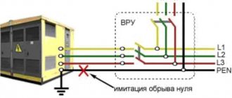
Explain the purpose and operating principle of protective grounding (with diagrams)
Protective grounding is an intentional electrical connection to the ground or its equivalent of metallic non-current-carrying parts that may be energized.
The purpose of protective grounding is to eliminate the risk of electric shock to people when voltage appears on the structural parts of electrical equipment, i.e. when shorted to the body.
The operating principle of protective grounding is to reduce touch and step voltages caused by a short circuit to the housing to safe values. This is achieved by reducing the potential of grounded equipment, as well as by equalizing potentials by raising the potential of the base on which a person stands to a potential close in purpose to the potential of grounded equipment.
The scope of application of protective grounding is three-phase three-wire networks with voltages up to 1000V with an isolated neutral and above 1000V with any neutral mode.
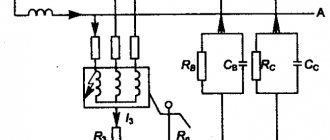
Fig.1 Schematic diagrams of protective grounding:
a – in a network with an isolated neutral up to 1000V and above
b – in a network with a grounded neutral above 1000V
1 – grounded equipment;
2 – protective grounding conductor
3 – working grounding conductor
rв and ro – resistance of protective and working grounding, respectively
Iв – ground fault current
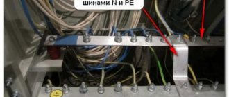
A grounding device is a combination of grounding conductors - metal conductors in direct contact with the ground, and grounding conductors connecting the grounded parts of the electrical installation to the grounding conductor. There are two types of grounding devices: remote and contour.
A remote grounding device is characterized by the fact that its grounding conductor is located outside the site on which the grounded equipment is located, or is concentrated on some part of this site.
This type of grounding device is used only for low values of ground fault current and, in particular, in installations with voltages up to 1000V, where the grounding potential does not exceed the permissible touch voltage. The advantage of this type of grounding device is the ability to choose the location of the electrodes with the lowest soil resistance.
A loop grounding device is characterized by the fact that its single grounding conductors are placed along the contour of the site on which the equipment being grounded is located, or distributed as evenly as possible over the entire site.
Safety with a contour grounding electrode is ensured by equalizing the potential in the protected area through the appropriate placement of single grounding electrodes.
Indoors, potential equalization occurs naturally through metal structures, pipelines, cables and similar conductive objects connected to an extensive grounding network.
Protective grounding is required for metal non-current-carrying parts of equipment that, due to faulty insulation, may be energized and which may be touched by people. At the same time, in rooms with increased danger and especially dangerous conditions for electric shock, as well as in outdoor installations, grounding is mandatory at a rated voltage of the electrical installation above 42V AC and above 110V DC, and in rooms without increased danger - at a voltage of 380V and above AC and 440V and above DC. Only in explosive areas is grounding carried out regardless of the purpose of the installation.
There are artificial grounding electrodes, intended exclusively for grounding purposes, and natural ones, metal objects located in the ground for other purposes.
For artificial grounding electrodes, vertical and horizontal electrodes are used. As vertical electrodes, steel pipes with a diameter of 3...5cm and steel angles with dimensions from 40*60 to 60*60mm and a length of 2.5...,m are used.
The following can be used as natural grounding conductors: water supply and other metal pipelines laid in the ground, with the exception of pipelines of flammable liquids, flammable or explosive gases, as well as pipelines coated with insulation to protect against corrosion. Natural grounding conductors, as a rule, have low resistance to current flow, and therefore their use for grounding purposes provides great savings. The disadvantages of natural grounding electrodes are their accessibility to non-electrical personnel and the possibility of disrupting the continuity of the connection of extended grounding electrodes.
Ground electrode depth
...from the collection “Grounding: Answers to Questions”
…Everywhere there is information that the corners (vertical) should be 2.5 meters long. We have 6 meters long for sale at the metal warehouse. I’m thinking of sawing it with two cuts into pieces of 2 meters each. And hammer them in at a distance of 2 meters from each other... Question. Is it critical that it is 2 meters and not 2.5 meters? Or do you need 2.5 m?
The soil is gray clay, always damp. Will I meet the required parameter limit (30 ohms)?======================================================= Not critical