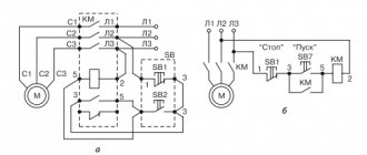
1.5.21
For 110 and 220 kV bypass switches with built-in current transformers, it is allowed to reduce the accuracy class of these current transformers by one step relative to that specified in 1.5.16.
For a 110 kV bypass switch and a 110 kV bus-connection (intersection) switch used as a bypass switch, with separate current transformers (having no more than three secondary windings), it is allowed to switch on the meter current circuits together with the protection circuits when using intermediate current transformers of an accuracy class of no more than 0.5; in this case, it is allowed to reduce the accuracy class of current transformers by one step.
The same inclusion of meters and reduction of the accuracy class of current transformers is allowed for a bus-connection (intersection) switch for a voltage of 220 kV, used as a bypass switch, with free-standing current transformers, and for a voltage of 110-220 kV with built-in current transformers.
Installation in residential buildings
It is not customary to install electric meters in apartments yourself.
For these purposes, employees of energy companies are called. In older multi-storey buildings, electric meters are located on common areas.
Today, there is a practice of moving meters from common corridors to apartments.
In modern new buildings, it is customary to install electric meters in electrical panels located in the hallways of apartments according to regulated rules. All the machines are located in the panel next to the meter. According to the PUE, the connection occurs to the incoming machine, and the main circuit is de-energized.
From the main machine, the electricity goes to the meter, and then through the wiring it is distributed to the machines. Grounding must be done to prevent short circuits.
You may also be interested in the article about installing electricity meters. Read an article about the features of replacing or moving an electric meter in an apartment here.
2.5.238
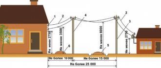
When crossing an overhead line with an underground communication cable and a power supply (or with an underground cable insert), the following requirements must be met:
1) the angle of intersection of overhead lines up to 500 kV with LS and LPV is not standardized, the angle of intersection of 750 kV overhead lines with LS and LPV should be as close as possible to 90°, but not less than 45°;
2) the distance from underground cables LS and LPV to the nearest ground electrode of an overhead line support with voltage up to 35 kV or its underground metal or reinforced concrete part must be at least:
in populated areas - 3 m;
in uninhabited areas - the distances given in Table 2.5.26.
Table 2.5.26 Shortest distances from underground cables LS (LPV) to the nearest ground electrode of the overhead line support and its underground part
| Equivalent earth resistivity, Ohm m | Shortest distance, m, at overhead line voltage, kV | ||
| Up to 35 | 110-500 | 750 | |
| Up to 100 | 10 | 10 | 15 |
| More than 100 to 500 | 15 | 25 | 25 |
| More than 500 to 1000 | 20 | 35 | 40 |
| More than 1000 | 30 | 50 | 50 |
The distance from underground LAN and LPV cables to the underground part of an ungrounded wooden support of an overhead line with voltage up to 35 kV must be at least:
in populated areas - 2 m; in cramped conditions, the specified distance can be reduced to 1 m, provided that the cable is laid in a polyethylene pipe at a length on both sides of the support of at least 3 m;
in uninhabited areas: 5 m - with an equivalent earth resistivity of up to 100 Ohm m; 10 m - with an equivalent earth resistivity from 100 to 500 Ohm m; 15 m - with an equivalent earth resistivity from 500 to 1000 Ohm m; 25 m - with an equivalent earth resistivity of more than 1000 Ohm m;
3) the distance from the underground cables of LAN and LPV to the nearest ground electrode of the overhead line support of 110 kV and above and its underground part must be no less than the values given in Table 2.5.26;
4) when laying an underground cable (cable insert) in steel pipes, or when covering it with a channel, an angle, or when laying it in a polyethylene pipe, closed on both sides from the ingress of earth, at a length equal to the distance between the overhead line wires plus 10 m with on each side from the outermost wires for overhead lines up to 500 kV and 15 m for overhead lines 750 kV, it is allowed to reduce the distances indicated in Table 2.5.26 to 5 m for overhead lines up to 500 kV and up to 10 m for 750 kV.
In this case, the metal covers of the cable should be connected to a pipe or other metal protective elements. This requirement does not apply to optical cables and cables with an external insulating hose, including those with a metal sheath. The metal covers of the cable insert must be grounded at the ends. When reducing the distances between the cable and the overhead line supports specified in Table 2.5.26, in addition to the given protection measures, it is necessary to install additional protection against lightning strikes by lining the supports with cables in accordance with the requirements of regulatory documentation for the protection of cables from lightning strikes;
5) instead of using a channel, angle or steel pipe, when constructing a new overhead line, it is allowed to use two steel cables with a cross-section of 70 mm, laid symmetrically at a distance of no more than 0.5 m from the cable and at a depth of 0.4 m. The cables must be extended on both sides at an angle of 45° to the route towards the overhead line support and grounded to a resistance of no more than 30 Ohms. The relationship between the length of the cable outlet and the grounding resistance must correspond to the values and given in Table 2.5.27;
Table 2.5.27 Resistance of grounding conductors when protecting LAN and LPV cables at the intersection with overhead lines
Installing an electricity meter in a private house - connection diagram
If we are talking about a large cottage with a lot of powerful equipment (water is heated from electricity, the house is heated, pumping stations operate, etc.), then it makes sense to organize a three-phase power supply, and accordingly you need to purchase a three-phase meter.
- The PUE conditions stipulate that the meter must operate in positive temperature conditions. You can put it in an insulated cabinet, install a light bulb or a heater in it to provide warmth, but who wants to do that? If the meter is in the cold, its working life is reduced (the owner pays for the device, he has to worry about it).
- In addition, in harsh street conditions, many meters begin to “fib”, and not always in favor of the owner.
- The owner paid for the device - it is his private property. The Civil Code in Article 210 states that the owner bears the burden of maintaining his property. How can this right be exercised if third parties have access to the meter?
- Sometimes, to create the appearance of protection from vandals, RES employees suggest mounting the meter higher, on a pole, for example. In this case, another rule from the PUE is violated. Thus, Chapter 1.5, clause 1.5.29 states that the height of placement from the floor or ground should be from 80 cm to 1.7 m.
7.1.38
Electrical networks laid behind impenetrable suspended ceilings and in partitions are considered as hidden electrical wiring and should be installed: behind ceilings and in the voids of partitions made of flammable materials in metal pipes with localization capabilities and in closed boxes; behind ceilings and in partitions made of non-combustible materials* - in pipes and ducts made of non-flammable materials, as well as flame retardant cables. In this case, it must be possible to replace wires and cables.
_______________
* Suspended ceilings made of non-combustible materials mean those ceilings that are made of non-combustible materials, while other building structures located above suspended ceilings, including interfloor ceilings, are also made of non-combustible materials.
General requirements. Electricity supply
7.1.13. Electrical receivers must be powered from a 380/220 V network with a TN-S or TN-CS grounding system.
When reconstructing residential and public buildings with a network voltage of 220/127 V or 3 x 220 V, the network should be switched to a voltage of 380/220 V with a TN-S or TN-CS grounding system.
7.1.14. External power supply to buildings must meet the requirements of Chapter 1.2.
7.1.15. In dormitories of various institutions, in schools and other educational institutions, etc. the construction of built-in and attached substations is not allowed.
In residential buildings, in exceptional cases, it is allowed to place built-in and attached substations using dry-type transformers in agreement with state supervisory authorities, while sanitary requirements for limiting noise and vibration levels must be fully met in accordance with current standards.
The construction and placement of built-in, attached and free-standing substations must be carried out in accordance with the requirements of the chapters of Section. 4.
7.1.16. It is recommended that power and lighting electrical receivers be powered from the same transformers.
7.1.17. The location and layout of transformer substations must provide for the possibility of round-the-clock unhindered access to them for personnel of the energy supply organization.
7.1.18. Power supply for safety lighting and evacuation lighting must be carried out in accordance with the requirements of Chapter. 6.1 and 6.2, as well as SNiP 23-05-95 “Natural and artificial lighting”.
7.1.19. If there are elevators in the building, which are also intended for transporting fire departments, their power supply must be provided in accordance with the requirements of Chapter. 7.4.
7.1.20. Electrical networks of buildings must be designed to power advertising lighting, shop windows, facades, illumination, outdoor, fire-fighting devices, dispatch systems, local television networks, light indicators of fire hydrants, safety signs, bell and other alarms, light fencing lights, etc., in in accordance with the design specifications.
7.1.21. When supplying single-phase consumers of buildings from a multiphase distribution network, it is allowed for different groups of single-phase consumers to have common N and PE conductors (five-wire network) laid directly from the ASU; combining N and PE conductors (four-wire network with PEN conductor) is not allowed.
When supplying single-phase consumers from a multiphase supply network with branches from overhead lines, when the PEN conductor of the overhead line is common to groups of single-phase consumers powered from different phases, it is recommended to provide protective shutdown of consumers when the voltage exceeds the permissible limit, arising due to load asymmetry when the PEN breaks conductor. The disconnection must be carried out at the entrance to the building, for example, by influencing the independent release of the input circuit breaker using a maximum voltage relay, and both the phase (L) and neutral working (N) conductors must be disconnected.
When choosing devices and devices installed at the input, preference, other things being equal, should be given to devices and devices that remain operational when the voltage exceeds the permissible voltage, arising due to load asymmetry when the PEN or N conductor breaks, while their switching and other performance specifications may not be met.
In all cases, it is prohibited to have switching contact and non-contact elements in PE and PEN conductor circuits.
Connections that can be disassembled with a tool are allowed, as well as connectors specially designed for this purpose.
Installing an electricity meter on a pole
- the input line must be de-energized. To do this, you will need to obtain the consent of the electricity supplier;
- the wires through which electricity enters the house are first connected to the circuit breaker, and then to the meter itself;
- Particular attention should be paid to the arrangement of grounding. It is necessary in order to protect electrical appliances;
- then the wiring to the house is connected to the meter output.
We recommend reading: Is it possible to return the Robot Dog to the Children's World?
When all apartments had induction electric meters, craftsmen invented various ways to change their readings downwards. With the advent of electronic analogs, this became almost impossible.
7.1.48
Installation of plug sockets in bathrooms, showers, soap rooms of baths, rooms containing heaters for saunas (hereinafter referred to as “saunas”), as well as in washing rooms of laundries is not allowed, with the exception of bathrooms in apartments and hotel rooms.
In the bathrooms of apartments and hotel rooms, it is allowed to install plug sockets in zone 3 in accordance with GOST R 50571.11-96, connected to the network through isolation transformers or protected by a residual current device that responds to a differential current not exceeding 30 mA.
Any switches and sockets must be located at a distance of at least 0.6 m from the doorway of the shower stall.
Security measures
To ensure safe operation and repair work of electric meters, it is customary to install special safety devices that make it possible to disconnect the device from the network.
The main provisions of the law on the replacement of electricity meters can be found here:
Such switches are attached to the location of the electricity meter. The distance should be no more than ten meters.
There is a practice of not particularly approving the installation of such fuses by representatives of energy services. Therefore, to avoid suspicion of theft of electrical energy, it would be advisable to seal them, just like an electric meter.
Construction company LLC “Artpaint”. Construction of engineering networks and communications
Crossing underground networks
In a modern city, intersections of underground networks are inevitable. The location of pipelines and cables at these intersections is determined by design, operational and sanitary requirements.
Structural requirements include the independence of settlement of different networks at the intersection under the influence of permanent and temporary loads. Based on this, one pipeline should not be allowed to directly rest on another, as this could result in fractures of the upper or lower pipeline.
To ensure independent settlement, the distance between the outer walls of the pipes should be about 15 cm.
According to operational and technical conditions, there must also be a certain distance between individual vertical communications, sufficient for the repair of individual networks.
In all cases of intersection of water pipes with gas pipelines and heat pipes, the vertical distance between them must be at least 0.15 m and in exceptional cases - 0.10 m. Water pipes can be passed through channels in which heat pipes are located.
It is recommended to lay water pipes at the intersection with sewer pipes higher than the latter, but in practice this is not always possible. Sewer pipes laid above water pipes at a length of 3-4 m must be metal (preferably cast iron) at the intersection.
If a medium-diameter sewerage system, consisting of ceramic or link concrete pipes, is laid above the water supply system, then at the intersection site the sewerage pipes should be embedded in concrete masses.
When crossing gas pipelines, heating pipelines or water pipelines at the same level with gravity sewers and drains on metal pressure pipelines, it is necessary to arrange contours near the gravity lines.
If a gas pipeline crosses a sewer or drainage collector, then in exceptional cases it is allowed to pass the gas pipeline through the collector. In this case, it is necessary to enclose the gas pipeline in a steel casing, the ends of which must be brought out at least 0.5 m from the outer surface of the collector walls, and there should be no pipe joints within the casing.
When drainage and sewer pipes intersect at the same level, a difference may be created on one of them, depending on local conditions. But in some cases, the differential device is inconvenient and uneconomical, especially on collectors. Therefore, a sewer pipe, as a permanent one, can be laid in the form of a siphon under a drain in compliance with all design requirements for siphons.
Underground networks when crossing tram tracks should be located at a depth of at least 1 m from the base of the rail to the top of the pipe or cable casing and laid at right angles or at least 75° to the track axes.
Typically, the normal depth of laying metal pipelines in order to reduce the influence of stray electric currents should be at least 1.5-2 m. In this case, the pipelines must have reliable coatings and be laid in a wooden or asbestos-cement case with bitumen filling the gap between the pipe and the case with a thickness of 25-20 m. 50 mm. The case must have a length of at least 2 liters from the outermost threads of the rail tracks.
When crossing power cables (as well as power cables with communication cables) laid directly into the ground, the distance between them must be at least 0.5 m. Communication cables should be located above the power cables. The required distance between pipelines and cables is 0.5 m. If for some reason this distance needs to be reduced, then the pipelines are separated from the cables by fire-resistant plates or the cables are enclosed in pipes. In this case, the vertical distance between communications is allowed to be at least 250 mm.
If there are a number of pipelines, cables and channels at street intersections, it is advisable to arrange underground chambers in which the intersection of all pipelines and control of the fittings installed on them are concentrated.
The design of these cameras is similar to cameras on combined collectors.
Availability of state verification
It is possible to install electricity meters in residential premises if there is a state verification, the deadline for which has not yet passed.
There are different verification periods for different types of meter:
- for a three-phase meter – 1 year;
- for a single-phase meter – 2 years.
Even when purchasing, it is necessary to check the statute of limitations, since it does not matter whether the meter was in operation or not. The date of verification is indicated on the seal of the meter body, Roman numerals indicate the quarter of the last check, and Arabic numerals indicate in which year it was checked. These deadlines are also regulated by the PUE.
2.1.49
For stationary electrical wiring, predominantly wires and cables with aluminum conductors should be used. For exceptions, see 2.1.70, 3.4.3, 3.4.12, 5.5.6, 6.5.12-6.5.14, 7.2.53 and 7.3.93.
Table 2.1.2. Selecting types of electrical wiring, installation methods and wires and cables
| Conditions environment | Type of electrical wiring and installation method | Wires and cables |
| Open wiring | ||
| Dry and wet areas | On roller skates and skating | Unprotected solid wires |
| Dry rooms | Same | Twisted two-core wires |
| Premises of all types and outdoor installations | On insulators, as well as on rollers intended for use in damp places. In outdoor installations, rollers for damp places (large sizes) may only be used in places where there is no possibility of direct rain or snow coming into contact with the electrical wiring (under canopies) | Unprotected solid wires |
| Outdoor installations | Directly on the surface of walls, ceilings and on strings, strips and other supporting structures | Non-metallic and metallic sheathed cable |
| Premises of all types | Same | Unprotected and protected single and multi-core wires. Cables with non-metallic and metallic sheaths |
| Premises of all types and outdoor installations | On trays and in boxes with openable lids | Same |
| All types of premises and outdoor installations (only special wires with a supporting cable for outdoor installations or cables) | On ropes | Special wires with a supporting cable. Unprotected and protected single and multi-core wires. Cables with non-metallic and metallic sheaths |
| Hidden electrical wiring | ||
| Premises of all types and outdoor installations | In non-metallic pipes made of combustible materials (non-self-extinguishing polyethylene, etc.). In closed channels of building structures. Under the plaster | Unprotected and protected, single and multi-core wires. Non-metallic sheathed cables |
| Exceptions: | ||
| 1. The use of insulating pipes with a metal sheath in damp, especially damp rooms and outdoor installations is prohibited. | ||
| 2. It is prohibited to use steel pipes and steel blind boxes with a wall thickness of 2 mm or less in damp, especially damp rooms and outdoor installations. | ||
| Dry, wet and damp areas | Embedded in building structures during their manufacture | Unprotected wires |
| Open and hidden electrical wiring | ||
| Premises of all types and outdoor installations | In metal flexible sleeves. In steel pipes (ordinary and thin-walled) and blind steel boxes. In non-metallic pipes and non-metallic blind boxes made of fire-resistant materials. In insulating pipes with metal sheath | Unprotected and protected single and multi-core wires. Non-metallic sheathed cables |
| Exceptions: | ||
| 1. The use of insulating pipes with a metal sheath in damp, especially damp rooms and outdoor installations is prohibited. | ||
| 2. It is prohibited to use steel pipes and steel blind boxes with a wall thickness of 2 mm or less in damp, especially damp rooms and outdoor installations. |
Table 2.1.3. Selecting types of electrical wiring and methods of laying wires and cables according to fire safety conditions
Installation of an electricity meter
But there is one more provision of the same document - PUE. According to clause No. 1.5.27, the electricity meter must be placed in dry rooms where the temperature does not fall below 0 0C. In addition, energy sources, requiring installation outside the building (on a pole, facade of a building, etc.), come into conflict with the Civil Code.
- Electronic meters that record electricity consumption by converting the electrical signal first into an analogue and then into a pulsed version;
- Induction meters that record energy consumption by simply counting the number of revolutions of an aluminum disk driven by induction currents.
We recommend reading: Regional Law on the 90th Anniversary
Now about grounding, grounding conductor and grounding conductor of a private house
Re-grounding of the neutral conductor when air powering the house can be done on a support pole or near the house.
Grounding on an overhead power line support
When installing an input device on a concrete support from which the power supply to the house branches off, it is quite justified and recommended to re-ground it using natural grounding conductors. As a natural grounding conductor, you can use the underground part of the support itself or its lightning protection circuit (clause 1.7.109-110, PUE).
Important! Re-grounding on a reinforced concrete pole is possible only if the overhead power line is made of insulated, self-supporting SIP type wires. Since they are mechanically stronger than wires without insulation
But still, if you want a more reliable, safe and independent grounding device for your home, it is better to make it using artificial grounding conductors.
Grounding a house with artificially made ground electrodes
House grounding is a grounding device, which consists of the following elements: a grounding conductor and a grounding conductor.
A grounding conductor is a conductor or several conductors connected to each other and having contact with the ground. A grounding conductor is connected to the grounding conductor, which is carefully brought out near the house and connected to the main grounding bus (GZSH). The cross-section of the grounding conductor must be no less than the cross-section of the PEN conductor.
Grounding electrodes can be made in different versions and be of different types.
- By type, grounding electrodes can be divided into: Vertical; Row; Ground loop.
- By type, grounding electrodes can be described as: Pin, Modular-pin, Loop and Foundation grounding electrodes.
The ground electrodes can be briefly described as follows:
The vertical grounding rod is a prefabricated copper or steel rod. The ground electrode is driven into the ground to a depth of 15-40 meters. In another way it is called a deep grounding electrode. The most modern type of home grounding. Does not require large excavations. (Details about deep grounding)
Row grounding. This is a prefabricated structure consisting of individual metal pins driven into the ground to a depth of 3-4 meters and connected by a metal strip. The distance between the pins must be at least 3 meters. The pins can be arranged in a row or in a triangle. Used only for secondary grounding. (Details on how to make in-line grounding)
The ground loop is made around the house in the form of a closed structure. The design of the ground loop also involves driving a pin into the ground. The pins are located along the perimeter of the foundation at a distance of 1 meter from it. The grounding pins are connected with a steel strip. Recommended for two lightning rods from the roofs and more than one power supply to the house. (Details about ground loops)
The foundation grounding system is made at the initial stage of building a house. The ground electrode is placed in the foundation of the house. Of all the ground electrodes, the foundation ground electrode is perhaps the most effective. (Details about foundation grounding)
Important! Whatever ground electrode you use in your home grounding device, the resistance to current spreading of the ground electrode should not exceed 10 Ohms for a linear voltage of 380 volts and 20 Ohms for a linear voltage of 220 volts with a three-phase power supply. And with a single-phase power supply, the resistance to current flow should not exceed 5 Ohms for 380 volts and 10 Ohms for a 220 volt power supply
(Details about measuring ground resistance)
And with a single-phase power supply, the resistance to current flow should not exceed 5 Ohms for 380 volts and 10 Ohms for a 220 volt power supply. (Details about measuring ground resistance)
Reading construction forums, I see that many do without secondary grounding in country houses. Grounding of the supply overhead line is considered sufficient. But still, you need to be guided not only by savings, but also by safety precautions for your family and property.
Elesant.ru
Normative references
- PUE, Electrical Installation Rules, edition 7
- GOST 121.030-81, Electrical safety. Protective grounding. Zeroing.
Other articles in the section: House electrical wiring
- 26 Rules for power supply and wiring of a wooden house. part 1, rules 1-7
- 26 Rules for power supply and wiring of a wooden house. part 2, rules 8-13
- 26 Rules for power supply and wiring of a wooden house. part 3, rules 14-26
- Anchor clamps and brackets
- Fittings for SIP 2
- Inserting cables from the trench into the house
- Input device. VU for a private house
- VRU. House input and distribution device
- GZSH. Main Grounding Bus
- Deep ground electrode
Rules for installing an electric meter in an apartment
Often, electricity meter installation in apartments is carried out by representatives of the network company. First of all, in the process of installing and connecting the meter, follow the rules of the Electrical Installation Regulations, which describe all the main aspects.
Important nuances
First of all, before installing the meter, you need to check the state inspection period. The seal must bear the date of inspection. The statute of limitations for state verification should not be higher than 1 year for 3-phase meters, 2 years for single-phase meters.
As a rule, meters are mostly installed in distribution panels on apartment sites. If the meter is installed directly in the apartment itself, where the input is located, then it is best to mount it in the hallway in a special closed panel. In this panel you can also place a group of machines for the entire apartment.
Meter installation process
- We are preparing a place for installing an electrical panel with machines and a meter.
- It is necessary to de-energize the input line. This can be agreed upon with the network provider or company electricians.
- The height for hanging the meter varies from 0.8 to 1.7 meters horizontally to the surface.
- Following the rules of the PUE, we switch the input and output circuits of the meter.
- Do not forget about protective grounding, which allows you to protect all electronics in the house in the event of a phase imbalance or short circuit.
- The input current circuit must be connected to the circuit breaker and then to the meter.
- We connect the counter output to the input machine or group of machines.
- We perform a test run.
1.5.12
Reactive electricity meters must be installed:
1) on the same circuit elements on which active electricity meters are installed for consumers paying for electricity taking into account the reactive power allowed for use;
2) at connections of consumer reactive power sources, if they are used to pay for electricity supplied to the power system network, or control the specified operating mode.
If the enterprise, with the consent of the power system, supplies reactive electricity to the power system network, it is necessary to install two reactive electricity meters with stoppers in those circuit elements where the calculated active electricity meter is installed. In all other cases, one reactive electricity meter with a stopper must be installed.
For an enterprise that pays the energy supplying organization for the maximum permitted reactive power, it is necessary to install a meter with a maximum load indicator; if there are two or more metering points, the use of an automated electricity metering system.
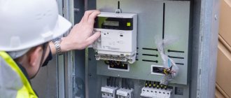
Rules for installing an electric meter on the street
Installation of an electric meter outdoors outside the premises must be carried out in accordance with a number of technical and operational requirements.
It is best to install the meter on the front side of the house at a height of 0.8-1.7 meters, which will provide easy access to it for representatives of the network company and technical service.
The meter can be mounted directly on the support of a concrete pillar if it is located on the premises of the house. Also, a circuit breaker should be installed in the electrical panel, and it is better to install a group of circuit breakers for all consumers in the house indoors.
Meter installation process
- Before installation work, it is necessary to disconnect the network line in accordance with the rules of the Electrical Installation Regulations.
- The height for hanging the meter varies from 0.8 to 1.7 meters horizontally to the surface.
- At temperatures below 5°C, electricity meters will behave incorrectly. It is for this reason that you should think about a heated electrical panel.
- The input current circuit must be connected to the circuit breaker and then to the meter.
- Do not forget about protective grounding, which allows you to protect all electronics in the house in the event of a phase imbalance or short circuit.
- We connect the counter output to the input machine or group of machines.
- Test activation.
What to do if the meter is asked to be taken outside
Recently, questions about moving the meter outside have become more frequent. People ask whether such demands are legitimate. A few days ago, this useful comment appeared in this article:
You can read this comment below, and if necessary, ask Dmitry what to do in your situation.
Here is another comment that may be useful to many:
I (Alexander (Foreman)) would recommend contacting a lawyer on these issues.
We also recommend: