DC machines: what is it?
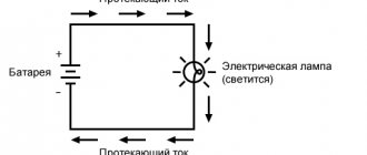
The use of electric current mainly consists of converting it into other types of energy, in particular mechanical.
Mechanical energy can also be converted into electrical energy. These transformations are carried out by direct and alternating current machines. In the first, direct current is supplied to the excitation winding.
Direct current machines (DCMs) that convert mechanical energy into electricity are called generators. Those performing the reverse conversion are engines.
Device
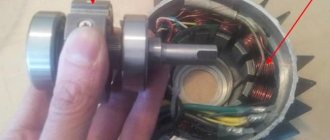
MPT consists of two parts:
- inductor : stationary part;
- armature : rotates inside the inductor.
In AC machines, the inductor and armature are usually called stator and rotor, respectively. The inductor creates a primary magnetic field that acts on the armature in order to induce an EMF in it (generator) or force it to rotate (motor).
In low-power MPTs, the inductor is sometimes a permanent magnet, but more often, in order to achieve a uniform magnetic flux, an electromagnet is used, that is, a system of coils that creates a magnetic field (excitation winding) when a direct current flows through them.
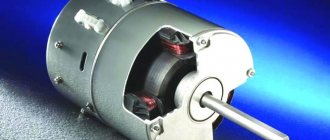
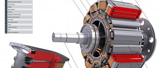
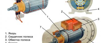
Design of a DC machine
Each coil is wound on a core, together they form a magnetic pole. For proper distribution of magnetic flux, the core is equipped with a special tip. There can be several main poles. In addition to them, additional ones are used to ensure spark-free operation of the collector. The latter is an important element of MPT; its function will be discussed below.
The inductor yoke is also the MPT frame, which is why it is usually called that. Magnetic poles and bearing shields are attached to it (the armature shaft rotates). In essence, the yoke is only a part of the frame along which the magnetic fluxes of the main and additional poles are closed.
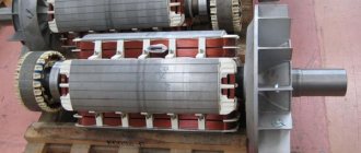
The armature is a core with grooves containing a wire laid in a certain order - a winding. The core is mounted on a shaft rotating in bearings. The collector is also fixed here.
The collector provides the ability to supply power to the rotating armature winding. It is a moving part of the so-called sliding commutator contact, and consists of several segment-shaped copper plates isolated from each other, mounted in the form of a cylinder on the armature shaft. The fixed part of the contact is represented by graphite or copper-graphite brushes fixed in brush holders. They are pressed against the collector plates by springs.
Operating principle
The operating features of the MPT depend on the mode in which it operates - generator or engine. Both options are discussed in detail below.
Generator
The operating principle of a direct current generator is based on the phenomenon of electromagnetic induction. It consists in the fact that when the magnetic flux crossing the conductor changes, an emf is induced in the latter.
Operating principle of a DC generator
To achieve a change in the magnetic flux, the field parameters are changed or the conductor is moved in a constant field. The second option is how the DC generator works: the armature winding is driven into rotation by an external mechanical force.
Obviously, after rotating the winding turns by 180 degrees, the EMF will be directed in the opposite direction. The collector helps keep the current in the circuit connected to the generator constant, that is, unidirectional: at the right moment, it reconnects the ends of the armature winding to the opposite contacts of the circuit (brushes). That is, in this machine the collector plays the role of a mechanical rectifier.
If there are only two main poles, the current will be pulsating. Increasing the number of poles leads to smoothing of the pulsations.
Engine
The operation of the MPT in motor mode is due to the appearance of the so-called ampere force. It acts on a conductor placed in a magnetic field when current flows through it. The direction of the ampere force is determined by the left-hand rule.
The Ampere force appears due to the following mechanism:
- when current flows around a conductor, a magnetic field arises with lines of force concentrically surrounding the conductor (circular field);
- the vector of its induction on one side of the conductor is co-directed with the induction vector of the primary magnetic field in which the conductor is placed. On this side the primary field is intensified;
- on the other side, the vector of the field induced by the electric current is directed opposite to the induction vector of the primary field, respectively, here it is extinguished;
- the difference in field induction on both sides of the conductor activates the occurrence of this force. It is determined by the formula: F = B * I * L, where: B is the magnetic induction of the primary field, I is the current strength in the conductor, L is the length of the conductor.
As in the case of a generator, after turning the armature winding to a certain position, switching contacts is required to change the direction of the current in it or the polarity of the inductor. Therefore, in engine mode, a commutator is also necessary.
Commutator motors have advantages:
- simplicity and wide range of adjustment;
- rigid mechanical characteristics (torque remains stable).
The disadvantage is the low reliability of the collector and its complexity, which negatively affects the cost of the engine.
Here are the undesirable phenomena that accompany the operation of the node:
- sparking;
- clogging with conductive graphite dust (brushes are made of this material);
- the appearance of interference in the network;
- under significant load - annular sparking (“all-round fire”), leading to burnout of the collector plates.
In order to combat shortcomings in some modern direct current motors (DCMs), the following solutions have been applied:
- The armature and inductor windings are swapped: the first is placed on the stationary part (stator), the second on the rotating part (rotor). The sliding contact remains, but due to the low load in the excitation winding, it is much simpler and more reliable than the commutator-brush contact;
- switching between the windings of the armature, now located in the stationary part, is carried out using semiconductor switches, triggered by a signal from the rotor position sensor. That is, the mechanical switch (collector) is replaced by an electronic one.
Such motors are called brushless motors, or BLDC motors abroad.
Working moments
Let's look at some characteristics and features of DC machines.
Start and reverse mode
A speed controller is connected to the electric motor
At the moment when the engine starts, the armature is in a stationary position, which means that the emf in it is zero. Due to the fact that the resistance of the armature winding is very small, the inrush current of the armature is much higher than the rated current. If you imagine starting an engine like this, it would definitely fail.
- To prevent this from happening, the starting current in DC motors with parallel excitation is limited due to the starting rheostat included in the circuit.
- In this case, the start must be carried out at the rated value of the magnetic flux, due to which the starting torque increases and the EMF in the armature winding quickly increases. As a result, the motor accelerates faster, and the time when a large starting current passes through the winding is reduced.
- When engine acceleration is completed, the rheostat is removed from the circuit - this is done either smoothly or stepwise.
- In order to stop the engine, it is enough to turn off the power supply to it.
- For any electric motor, a rotation mode in the opposite direction is available - reverse. To do this, you just need to change the direction of the current either in the armature winding or in the stator winding.
Interesting to know! Changing the direction of currents at the same time will lead to nothing; the motor will continue to rotate in the same direction.
Power loss and efficiency
Even the most technically advanced DC motor cannot operate without loss of power
Any DC motor or generator operates with power losses. They are divided into two types: basic and additional.
- The first include magnetic, electrical and mechanical.
- Magnetic losses occurring in steel are designated ΔРс. They occur due to the fact that during rotation the core on the armature is constantly remagnetized, so losses due to hysteresis and eddy currents occur.
- Electrical losses (ΔRel) occur due to the active resistance of the windings, as well as the resistance of the brush contact, that is, this value is presented as the sum of the specified losses.
- Mechanical (ΔРmech) include friction losses of bearings, friction of brushes on the commutator, friction of a rotating armature on air (and there is such a thing) and ventilation losses.
- All other losses are called incremental and they are mainly associated with the interaction of various parts of the unit with the magnetic field.
Losses are negligible when there is no load
Interesting to know! Power losses when operating in idle mode, that is, without load, are extremely small.
To calculate each type of loss, special formulas are used. We will not go into the essence so deeply, but will only say that the efficiency of a DC machine is determined by the ratio of the output power to the consumed one. This value is usually expressed as a percentage.
Modern DC machines have become very efficient. Their efficiency usually varies between 75-90%.
Performance characteristics
Performance characteristics of DPT
The performance characteristics are as follows:
- Rotation speed, current consumption and motor power;
- Efficiency from useful power, provided that the supply voltage remains constant.
- Excitation winding current and the absence of additional resistance in the armature circuit.
All these parameters allow us to talk about the properties of engines in operating mode, as well as to find optimal and economical modes of their operation.
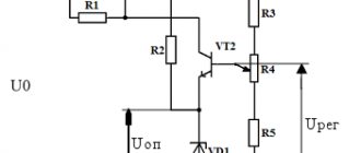
Adjusting the engine speed
Schematic diagram of the rotation speed controller
You can regulate the rotation speed of a DC machine in three ways: changing the network voltage, rheostatic regulation, changing the magnetic flux. Let's talk about everything in order.
- The voltage change is carried out by devices that can, in fact, change the voltage value.
- Rheostat control, as we already mentioned throughout the article, requires the introduction of additional active-type resistors into the armature circuit, that is, those that change their characteristics under certain conditions.
- The magnetic flux is regulated by reducing the excitation current.
Of course, we have not named all the characteristics of DC machines, but only the main ones, but this is quite enough to get acquainted with these units.
The video in this article will demonstrate how these devices work.
Classification of MPT according to the method of powering the inductor and armature windings
Based on this feature, MPTs are divided into 4 types.
With independent excitation
The inductor and armature windings have no electrical connection. In generators of this type, the excitation winding is powered by a direct current network, a battery, or a generator specially designed for this purpose - an exciter. The power of the latter is several hundredths of the power of the main generator.
Scope of application of generators with independent excitation:
- systems of significant power, where the voltage on the excitation winding differs significantly from the generated one;
- systems for regulating the rotation speed of engines powered by generators.
For motors with independent excitation, the armature winding is also energized. Basically these are also high-power units.
The independence of the inductor winding makes it more convenient and economical to regulate the excitation current. Another feature of such motors is the constancy of the excitation magnetic flux under any load on the shaft.
With parallel excitation
The inductor and armature windings are connected in one circuit parallel to each other. Generators of this type are usually used for medium power. In a parallel connection, the voltage generated by the device is applied to the excitation winding. When the inductor and armature windings are connected into one circuit, they speak of a self-excited generator.
In motors with parallel excitation, the inductor is supplied with the same voltage and from the same power source as the armature.
In terms of their characteristics, they are identical to motors with independent excitation and have the following features:
- when the load changes, the rotation speed is practically not transformed: the deceleration is no more than 8% when transferring from idle to rated load;
- it is possible to regulate the rotation speed with minimal losses, and within a wide range - 2 times, and for specially designed motors, 6 times.
The inductor of a rotating parallel-wound motor cannot be disconnected from the armature circuit, even if it is already disconnected. This will lead to the induction of a significant EMF in the excitation winding with subsequent failure of the motor. Personnel nearby may be injured.
With sequential excitation
The windings are connected in series to each other. The armature current flows through the field winding. Generators of this type are almost never used, since the process of self-excitation occurs quite rapidly and the device is not able to provide the constant voltage required by most consumers. They are used only in special installations.
Series excitation circuit
Motors of this type are widely used as traction motors (electric locomotives, trolleybuses, cranes, etc.): compared with parallel excitation analogues, when loaded they produce a higher torque with a simultaneous decrease in rotation speed. The starting torque is also high.
Starting the engine with a load below 25% of the rated load, and even more so at idle, is unacceptable: the rotation speed will be too high and the unit will fail.
With parallel-series (mixed) excitation
There are two types of scheme:
- the main winding of the inductor is connected in parallel with the armature winding, the auxiliary winding is connected in series;
- The main winding of the inductor is connected in series with the armature winding, the auxiliary winding is connected in parallel.
Schemes of MPT excitation systems
Connecting a parallel winding before a series winding is called a “short shunt”, and after a series winding - a “long shunt”. Generators of this type are used extremely rarely.
The engines combine the advantages of analogues with parallel and series excitation: they are able to operate at idle speed and at the same time develop significant traction force. But they are almost never used today.
Contents Previous § Next10.8. Unified Series of DC Machines
Currently, the main series of general purpose machines are the 2P series - with a power from 0.37 to 200 kW and P2 - with a power from 315
up to 10 MW. A series of generators and engines for special purposes are also produced: crane, traction, ship, for driving rolling mills, etc.
Manufactured engines must comply with the passport data. They undergo special tests:
measurement of winding resistance at direct current; the resistance should not differ by more than ±10% from the nominal;
measuring the insulation resistance of the windings relative to the housing and between the windings;
testing the insulation of the windings relative to the housing and between the windings with increased voltage - usually test voltage (Usp = 2 (/Nom + + 1000 V;
testing at an increased speed, which must be 20% more than the maximum specified in the passport, or 20% more than the nominal speed if the maximum speed is not indicated; The exception is for motors with series excitation, the test rotation speed of which must be at least 50% higher than the rated speed (if the maximum is not specified);
checking the nominal data of the machine: rotation speed, no-load voltage, etc.;
checking switching at rated load and with a short-term overcurrent of 1.5 times for 1 minute.
Additional tests may be carried out, which are provided for by GOST and
special technical conditions.
Single series
2P. It covers engines in the power range of 0.37... 200 kW with axis heights of 90... 315 mm. Rotation heights, installation and connection dimensions comply with IEC recommendations.
2P series motors are low voltage: rated voltage
armatures PO, 220, 340 and 440 V. All motors have independent excitation with a rated voltage PO or 220 V.
All motors have a compensation winding, the use of which makes it possible to reduce dimensions and obtain machines with good switching and not prone to all-round fire.
The frame has a cylindrical shape with cut-out windows for the exit of cooling air from the free end of the shaft and for servicing the commutator and brush apparatus on the other side. Small engine frames (with a rotation axis height of up to 200 mm) are made from standard seamless steel pipes. The frame of large-sized engines is made of thick sheet steel using the rolling method followed by welding.
Bearing shields are flat, cast iron, with stiffeners. For small-sized engines (with a rotation axis height of up to 100 mm), they are also made of aluminum alloy.
The bearings on the collector side are ball bearings of the middle series, thrust. On the drive side, roller bearings are installed in large engines, and ball bearings in small engines.
The armature core is made from stamped sheets of cold-rolled isotropic steel 0.5 mm thick.
The armature winding of motors with a rotation axis height of up to 200 mm is loose and fits into semi-closed grooves. The armature winding of large-sized motors is a coil winding, made of rectangular wire, placed in open slots. PETV wire insulation. Body insulation made of composite material based on mica plastic, “sheet” type.
Engines of the 2P series are produced in protected (1P22) or closed (1P44) versions.
The third letter in the designation of the car brand (first written 2P) indicates the type of protection and ventilation.
Protected machines are made with self-ventilation (letter H) or with independent ventilation from an external fan (letter F).
At a rotation speed of 1500 rpm, engines of the same size have approximately the same power. At lower speeds, motors with self-ventilation (N) have less power than motors with independent ventilation (F), since at low speeds the efficiency of the fan built into the engine decreases. At n>1500 rpm, the power is greater for self-ventilated engines; at ha=3000 rpm this difference in power is approximately 30%. The advantage of independently ventilated motors is that they allow operation at low speeds without reduction in torque (i.e. armature and field current).
The cost of a 2PF motor is 8% higher than that of a 2PN motor of the same size (with the same height of the rotation axis and length). Approximately 8... 12% more is the weight of the motor.
Enclosed motors with natural cooling 2PB have a power 1.5... 3.0 times less than 2PN motors of the same size, since the cooling conditions of the windings in closed motors are much worse than in protected ones. The cost of 2PB engines is 10% higher than that of 2PN.
Enclosed motors with external airflow from an external 2PO fan have a power approximately 1.5 times greater than 2PB motors of the same size. The cost of 2PO engines is 18% higher than that of 2PN engines, and their weight is approximately 10% more. With the same height of the rotation axis, motors are produced with the same armature and stator diameters, but with armatures of two different lengths and, naturally, with different powers.
The nature of the dependence of engine power on rotation speed and height of the rotation axis is shown in Fig. 10.19. At the same height of the rotation axis, the power is proportional to the rotation speed, i.e. it is determined by the torque. Consequently, in this series the mass of the machine is determined by the height of the axis of rotation (Fig. 10.19 curve 1).
The same figure (curve
2)
shows the price of the machine
C,
which directly depends on the mass
M.
The ratio
C/M = 6.0 ...
2.5 rubles/kg.
SM
values correspond to a higher height of the rotation axis, i.e., higher engine power.
This proves once again that
the economics 10.18. Dependence of the mass and price of a 2P series machine on the height of the rotation axis
Rice. 10.19. Dependence of the rated power of the 2P series machine on the height of the rotation axis
It is theoretically advisable to use one large machine instead of several machines of the same total power.
Standard values for the height of the rotation axis for machines of the 2P series: 90,
112,
132, 160, 180, 200, 215, 250, 280 and 315 mm.
The power, weight and price values of the corresponding engines (at length L)
are shown in the graphs in Fig. 10.18 and 10.19 with asterisks.
Series 4P.
A new 4P series with a wide range of speed control has been developed and is being introduced.
The cross-section of the magnetic core has a polyhedron shape, which makes it possible to place the main and additional poles and their windings more compactly than in a machine with a round frame. Thanks to this, a multifaceted machine has a power 15 ... 20% greater than a machine with a round bed of the same dimensions, since at the same height of rotation the diameter of the armature is larger.
To increase power in 4P series engines at a given height of the rotation axis, the armature length is longer than in 2P series engines.
The insulation of the armature and stator windings has heat resistance classes H and F.
Improved cooling, especially of the stator.
A compensation winding and a fully laminated stator core are used to increase the speed control range by weakening the magnetic field and to ensure satisfactory switching during transients.
All of the above improvements have led to the fact that, at the same height of the rotation axis, engines of the 4P series have a power 1.5 ... 2.0 times greater than engines of the 2P series.
Series PI.
Currently, within the framework of the international organization for scientific, technical and economic cooperation Interelectro, a unified series of PI DC motors is being developed. The NRB, Hungarian People's Republic, Poland, SSR, USSR, Czechoslovakia and SFRY are involved in the development of engines of this series.
When developing this series, unification of the main output parameters of the engines, their characteristics, and installation and connection dimensions must be ensured.
Within the framework of the PI series, uniform requirements are established for technical and economic parameters, as well as for protection systems, indicator devices, etc. IEC recommendations are mandatory.
At the same time, the task of creating a unique design of parts and assembly units is not set. Specific decisions on the design of engines of the unified PI series can be made by countries individually, depending on the specifics of their technical and economic conditions
The PI series includes DC motors with rotation axis heights from 71 to 355 mm, with three lengths in dimensions
Rated power range at ha = 1500 rpm from 0.25 to 250 kW.
Motors are four-pole, with a laminated stator. Heat resistance class F insulation. Electromagnetic excitation, independent.
Motors of the PI series are designed for power supply from semiconductor converters with an armature current ripple coefficient of no more than 15%
The range of rotation speed control by weakening the field (by reducing the excitation current) for motors with a compensation winding is up to 1 5, and the power remains constant in the range 1 3
For motors without compensation winding, the range is 1 2
The motors can withstand double current load for 15 s and the rate of change of armature current during transient conditions is up to 200 1t/s
Basic data of PI series motors at /1=1500 rpm are given in Table 10 1
Table 10 1
Series D. Metallurgical and crane DC motors with a power of 2.5 ... 185 kW are designed for operation in lifting and transport mechanisms and electric drives of metallurgical units in conditions of high humidity, dust and vibration
Engines with a power of 2.5-37 kW are made with a cylindrical one-piece frame. With a power of 55 kW and above, the frame is made of a faceted detachable frame, which allows you to remove the armature for repairs without removing the engine from the mechanism in which it is built. This speeds up and reduces the cost of repairs
Motors of the D series are manufactured for voltages of 220 and 440 V, they are four-pole, class H heat resistance insulation
The motors do not have a compensation winding.
Basic data of D series engines are given in table. 10 2
Series P2. Motors in this series have power from 315 to 10,000 kW. They are closed with forced ventilation. This series is less common; along with it, specialized high-power machines are produced in large quantities
Motors for rolling mill drives. Special motors are produced with a power of up to 10,000 kW in a single-armature version and up to 16,000 kW in a double-armature version. These are closed machines with forced ventilation, armature voltage - 600 and 930 V, independent excitation
Balancing machines (BMB) Designed for testing other electrical machines; they are characterized by a wide range of speed changes. They operate as a brake generator or drive motor. They have a tachogenerator and a device for measuring torque.
Table 10.2
| Move- | Power- | Frequency | Maximum frequency | Weight, | A | |
| tel | power, kW | Current. A | rotation, rpm | rotation, rpm | kg | R in non"*" kgUkW |
| Slow-moving | ||||||
| D12 | 2,5 | 14,6 | 1140 | 3600 | 130 | 16,5 |
| D21 | 4,5 | 26 | 1000 | 3600 | 200 | 12,3 |
| D22 | 6,0 | 33 | 1070 | 3600 | 225 | 11,2 |
| D31 | 8,0 | 44 | 820 | 3600 | 310 | 8,82 |
| D32 | 12,0 | 65 | 740 | 3300 | 365 | 6,83 |
| D41 | 16,0 | 86 | 670 | 3000 | 540 | 7,5 |
| D806 | 22,0 | 116 | 635 | 2600 | 635 | 7,05 |
| D808 | 37,0 | 192 | 565 | 2300 | 885 | 5,9 |
| D810 | 55,0 | 280 | 540 | 2200 | 1250 | 5,6 |
| D812 | 75,0 | 380 | 500 | 1900 | 1770 | 6,2 |
| D814 | BY | 550 | 490 | 1700 | 2240 | 5,87 |
| D816 | 150 | 740 | 470 | 1600 | 2800 | 5,6 |
| D818 | 185 | 920 | 440 | 1500 | 3745 | 5,96 |
| Fast | ||||||
| D21 | 5,5 | 31 | 1400 | 3600 | 200 | 14,1 |
| D22 | 8,0 | 43,5 | 1450 | 3600 | 225 | 11,3 |
| D31 | 12,0 | 64 | 1310 | 3600 | 310 | 11,0 |
| D32 | 18,0 | 94 | 1140 | 3300 | 365 | 7,0 |
| D41 | 24,0 | 124 | 1060 | 3000 | 540 | 7,9 |
| D806 | 32,0 | 165 | 980 | 2600 | 635 | 7,5 |
| D808 | 47,0 | 240 | 770 | 2300 | 885 | 6,3 |
Contents Previous § Next