Good day everyone! My post today continues the story about linear voltage stabilizers. I'll tell you about compensation voltage stabilizers (or abbreviated as KSN).
A compensating voltage stabilizer is essentially a device in which the output value is automatically regulated, that is, it maintains the load voltage within specified limits when the input voltage and output current change. Compared to parametric ones, compensation stabilizers are distinguished by higher output currents, lower output resistances, and higher stabilization coefficients.
To assemble a radio-electronic device, you can pre-make a DIY KIT kit using the link.
Compensation stabilizers are of two types: parallel and series. Structural diagrams of compensation stabilizers are shown below.
Compensating voltage stabilizer of series type Compensating voltage stabilizer of parallel type
The main elements of all compensation voltage stabilizers are the regulating element P
;
source of reference (reference) voltage AND
;
ES
comparison element ;
DC
amplifier U.
Series compensating regulator
In series-type stabilizers, the control element is connected in series with the input voltage source U0 and the load RH. If for some reason the voltage at the output U1 deviates from its nominal value, then the difference between the reference and output voltages changes. This tension is amplified and affects the regulating element. In this case, the resistance of the regulating element automatically changes and the voltage U0 will be distributed between P and RH in such a way as to compensate for the voltage changes at the load that have occurred.
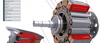
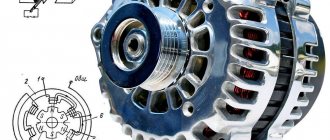
The regulating element in compensation voltage stabilizers is usually made of transistors. Choosing which is based on the values of the current transfer coefficient h21e, the saturation voltage between the collector and emitter UKENas.
Comparator circuits and DC amplifiers are very often combined and implemented using conventional amplifiers, differential amplifiers or operational amplifiers.
Let's consider the circuit of a series-type compensation voltage stabilizer.
Circuit of a simple series-type compensation voltage stabilizer
In this circuit, transistor VT1 performs the functions of a regulatory element, transistor VT2 is both a comparing and amplifying element, and zener diode VD1 is used as a reference voltage source. The voltage between the base and emitter of transistor VT2 is equal to the difference in voltages UOP and UREG. If for any reason the voltage across the load increases, then the voltage UREG increases, which is applied in the forward direction to the emitter junction of transistor VT2. As a result, the emitter and collector currents of this transistor will increase. Passing through resistance R1, the collector current of transistor VT2 will create a voltage drop across it, which in its polarity is reverse for the emitter junction of transistor VT1. The emitter and collector currents of this transistor will decrease, which will lead to the restoration of the rated voltage at the load. In the same way, you can trace changes in currents when the voltage across the load decreases.
Stepwise adjustment of the output voltage can be done using the reference voltage taken from a chain of series-connected zener diodes. Smooth adjustment is usually made using a voltage divider R3, R4, R5, connected to the output circuit of the stabilizer.
If we neglect the voltage drop at the emitter junction of transistor VT2, then the output voltage of the stabilizer
where R4' and R4'' are the upper and lower parts of the resistor R4, respectively, according to the circuit.
The simplest do-it-yourself voltage stabilizer
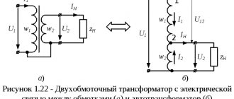
Let's look at how you can make your own 220-volt stabilizer with your own hands, having a few simple parts on hand. If the voltage in your electrical network is significantly reduced, then such a device will come in handy. To make it, you will need a ready-made transformer and a few simple parts. It is better to take note of such an example of a device, since it turns out to be a good device with sufficient power, for example, for a microwave.
For refrigerators and various other household devices, a decrease in network voltage is very harmful, more than an increase. If you increase the network voltage using an autotransformer, then while the network voltage decreases, the voltage at the device output will be normal. And if the voltage in the network becomes normal, then at the output we will get an increased voltage value. For example, let’s take a 24 V transformer. With a line voltage of 190 V, the output of the device will be 210 V; with a network value of 220 V, the output will be 244 V. This is quite acceptable and normal for the operation of household devices.
For manufacturing we need the main part - this is a simple transformer, but not an electronic one. You can find it ready-made, or you can change the data on an existing transformer, for example, from a broken TV. We will connect the transformer according to the autotransformer circuit. The output voltage will be approximately 11% higher than the mains voltage.
In this case, you need to be careful, since during a significant voltage drop in the network upward, the output of the device will produce a voltage that significantly exceeds the permissible value. The autotransformer will add only 11% to the line voltage
This means that the power of the autotransformer is also taken at 11% of the consumer’s power. For example, the power of a microwave oven is 700 W, which means we take a transformer of 80 W. But it’s better to take power with a reserve
The autotransformer will add only 11% to the line voltage. This means that the power of the autotransformer is also taken at 11% of the consumer’s power. For example, the power of a microwave oven is 700 W, which means we take a transformer of 80 W. But it is better to take power with a reserve.
The SA1 regulator makes it possible, if necessary, to connect the consumer load without an autotransformer. Of course, this is not a full-fledged stabilizer, but its production does not require large investments and a lot of time.
Homemade voltage stabilizer
Watch this video on YouTube
Improving stabilizer parameters
A simple compensation voltage stabilizer circuit can be improved by replacing resistor R1, which powers transistor VT2, with a current stabilizer circuit. This power supply method can significantly increase the stability of the DC amplifier.
In cases where high temperature stability of the Compensation Voltage Stabilizer and low time drift are required (especially at low output voltages), differential amplifier circuits are used. To improve the quality of the output voltage, the DC amplifiers of the stabilizer use operational amplifiers, which have a high gain and low temperature drift. The operational amplifier can be powered directly from the output voltage of the stabilizer.
Current stabilizer circuit. Connection of pins: 1 – to the VT1 collector, pin 2 – to the VT collector. Differential amplifier circuit. Connecting the terminals: 1 – to the emitter VT1, 2 – to the base VT1, 3 – to the cathode of the zener diode VD1, 4 – to the anode of the zener diode VD1, 5 – to the voltage divider.
Connecting a voltage stabilizer
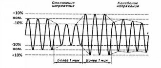
One of the reasons why household appliances and electrical appliances fail prematurely is sudden voltage drops in the electrical network.
To prevent these undesirable situations, stabilizers are used - protective devices that protect household and industrial equipment from interference and voltage distortion.
Protection is provided by an electronic circuit that monitors the value of the input voltage, which turns off the load when it goes beyond acceptable limits. The load is connected when the network parameter values return to acceptable limits.
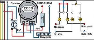
Diagram for connecting a voltage stabilizer to a 220 V network
The voltage stabilizer is connected when the network is de-energized. This is a basic safety requirement. To perform this, the input circuit breaker located in the distribution cabinet is turned off, after which it is necessary to finally verify that there is no voltage using a pointer.
In most cases, the stabilizer is turned on immediately after the meter, at the entrance to the room, before the load. Connection type – serial, in phase wire break. Quite often, manufacturers of electronic products designate the structural diagram of the stabilizer on the surface of the case.
The voltage stabilizer usually has three contacts for connection:
- – phase – “input”;
- – phase – “output”;
- – zero.
The phase wire from the input circuit breaker is connected to the “input” of the stabilizer. Then the load phase wire is connected to the “output”. The neutral wire of the network is connected to the neutral contact of the stabilizer without breaking.
To connect the neutral wire, you must first connect it to the stabilizer, and then to the common neutral wire of the network (using terminal connectors (blocks) or regular twisting).
What to do if there are four connection contacts on the stabilizer body?
In some cases, the voltage stabilizer circuit is designed in such a way that not three, but four contacts are used to connect it to the network:
- – phase – “input”;
- – zero – “input”;
- – phase – “output”;
- – zero – “exit”.
In this case, the voltage stabilizer circuit, according to which it is connected to the network, is performed as follows: the phase and neutral wires from the input circuit breaker (electrical panel) are connected to the corresponding “input” contacts on the protective device, and the phase and neutral load wires are connected to the “output” contacts "
After installation, you should carefully check that the wires are connected correctly. Before turning on the device for the first time (applying voltage to the input), it is necessary to disconnect all the load from its output (lighting, remove the plugs of electrical appliances from sockets, etc.).
After turning on the stabilizer, you need to check its operation; it should work stably and normally without extraneous noise, crackling, etc.
Some low-power voltage stabilizers (P
Calculation of a series stabilizer
An example of calculating a simple series-type compensating voltage stabilizer
Initial conditions: input voltage U0 = 24 V, input voltage instability ΔU0 = ± 2 V, maximum load current INmax = 1.5 A, stabilization coefficient KST ≥ 103. Provide for smooth adjustment of the output voltage ranging from UНmin = 12 V to UНmax = 16 V.
1. Determine the maximum collector-emitter voltage of the regulating transistor VT1:
2. Determine the maximum power dissipated by transistor VT1:
3. According to the calculation data, select transistor VT1, which satisfies the conditions:
These conditions are met by a P216V type transistor with the following parameters: UCEmax = 35 V, IC max = 7.5 A, PC max = 24 W, h21e = 30.
4. To create a reference voltage UOP, we select a Zener diode of type D814A with parameters UCT = 8 V, ICT = 20 mA, rDIF = 6 Ohm.
5. Let’s determine the maximum collector-emitter voltage of amplifying transistor VT2:
6. Based on the condition UCE2max < UCE max, we select a P416 type transistor with h21e = 90 ... 250 as an amplifying element.
7. Assuming that IK2 ≈ IE2 = 10 mA < IC max, we find the resistance of resistor R2:
8. Considering that IR1 = IC(VT2) + IB(VT1), IB(VT1) = IHmax / (1 + h21e(VT1)) = 1.5/(1 + 30) ≈ 48 mA, we determine the resistance R1:
9. Determine the resistance of resistors R3, R4, R5. Let’s agree to assume that if the potentiometer R4 slider is in the uppermost position, then the output voltage of the stabilizer has the minimum value UНmin specified by the condition. In the lowest position of the engine, the output voltage is maximum. Then we can write the equations
Believing
we get
Online calculator for calculating a compensation voltage stabilizer here.
Linear voltage stabilizers based on transistors and integrated circuits.
Online calculation of circuit elements of linear stabilizers with fixed and adjustable output voltage.To maintain stable operation and maintain the declared parameters of electrical equipment, in most cases it must be powered by a constant voltage that is not controlled by any external influences. Typically, this function is assigned to devices called voltage stabilizer . A voltage stabilizer is an electrical energy converter designed to maintain the output voltage level within specified limits when the following quantities change: input voltage, load resistance, and ideally, temperature and other external influences.
Not so long ago, such units were built on zener diodes and transistors, however, with the advent of specialized microcircuits, the need for independent design of such circuits quickly subsided, due to the obvious ease of implementation of stabilizers made on integrated circuits. But in vain!
Where the values of the stabilization coefficient Kst can be calculated in tens rather than hundreds or thousands, the simplest parametric stabilizer not only has the right to exist, but also outperforms its integral counterparts in such an important parameter as the purity of the output voltage and the absence of impulse noise at the moment of a sharp changes in load current. Let's look at these simplest voltage stabilizer devices.
Fig.1 a) The simplest circuit b) With an emitter follower c) With an adjustable output. voltage
The voltage stabilizer circuit shown in Fig. 1 a) is used mainly with devices through which significant currents do not flow. The value of the current Iin flowing both through the zener diode and through the load depends on the value of the resistor Rst. The magnitude of this current is calculated by the formula: Rst = (Uin - Ust)/ Iin , and Iin must satisfy the condition Iin ≥ In. max + Ist. min , where In. max is the maximum current in the load at a given output voltage, and Ist. min - the minimum stabilization current of the zener diode, specified in the characteristics of the semiconductor. In zener diodes of domestic manufacturers, the parameter Ist. min , as a rule, is specified explicitly; for foreign ones it may not be specified at all. Where should a poor Jew go? In this case, I would recommend focusing on the current value from the “Izk” datasheets (the value at which the zener diode has maximum impedance) and increasing this value by 2…3 times. Although, by and large, the optimal (from the point of view of achieving maximum parameters) current for a zener diode is the test current, at which the main characteristics of the semiconductor are measured.
For the zener diode to perform its tasks most efficiently, it is quite important that the load power does not exceed the power dissipated by the semiconductor. Therefore, if there is a need to stabilize the voltage in loads that consume significant power, an additional current amplifier is used - an emitter follower (Fig. 1 b)). In this case, the load for the zener diode is the input resistance of the repeater Rin ≈ Rн x (1 + β) , i.e. the load current can be increased by β times. Here it is important to take into account the voltage drop at the emitter junction of the transistor, and therefore the voltage at the output of the stabilizer will be 0.6...0.7 V (1.2...1.4 V for a composite transistor) less than the stabilization voltage of the zener diode .
By installing a variable resistor in parallel with the zener diode (Fig. 1c)), it becomes possible to change the stabilization voltage in the load from zero to almost the maximum value of the zener diode stabilization voltage (minus the voltage drop Ube at the transistor junction). Naturally, the current flowing through the variable must also be taken into account, setting its value - no less than the input current of the emitter follower. Let's spice up the material covered with a calculator.
TABLE OF CALCULATION OF LINEAR VOLTAGE STABILIZER ELEMENTS
Compensating linear stabilizer circuits are the basis of most integrated circuits that perform the function of stabilizing voltages and currents, and in their simplest form can be made using a zener diode and a pair of transistors (Fig. 2).
Fig.2 Circuits of compensation linear voltage stabilizers
Here the zener diode is a source of reference voltage, and transistor T2 is a device for comparing the output voltage supplied through a resistive divider to its base with the reference voltage at its emitter. The output voltage has increased, and along with it the voltage at the base of T2, the transistor opens slightly and attracts the voltage at the base of the regulating transistor T1 to the negative (ground) bus, thereby reducing the voltage at its emitter, and accordingly at the output of the circuit. The output voltage has decreased - everything is the same, only in reverse. Compensation stabilizers based on transistors have a higher stabilization coefficient compared to the devices presented in Fig. 1, but due to the presence of feedback they also have their drawbacks. In this regard, we will not dwell on them in detail, but will move directly to integrated stabilizers, which have a similar principle of operation, but are much more complex in structure, have higher characteristics and at the same time are very simple and easy to implement.
There are two types of such integrated circuits: adjustable voltage regulators and stabilizers with a fixed output voltage. In the second case, the stabilizer circuit takes on an indecently primitive appearance, unworthy of any serious discussion. In the case of regulators with adjustable output voltage, the circuit is still quite simple, but requires some mental manipulation associated with calculating the resistive divider to obtain the required output voltage.
A typical connection diagram for most adjustable microcircuits is shown in Fig. 3.
Fig.3
The formula for calculating the output voltage is Vout = Vref x (1+R2/R1) + Iadj x R2 , and the resistance value R1 is usually set by the chip manufacturer to achieve the best output characteristics.
To reduce pulsations, some fighters place additional electrolytes of significant quantities in parallel with resistor R2. Of course, these heroes are fighters, but why break the chairs? Any sudden increase in load current, leading to a decrease in the output voltage, will not be able to be processed immediately by the automatic adjustment circuit due to the delay in the feedback circuit caused by this capacitor, and this will significantly reduce the performance of the device. And if for static loads the speed parameter of the stabilizer on the drum, then for dynamic ones (for example, such as ULF) it is very important. Therefore, either these electrolytes are not needed at all, or (if Datasheet strongly recommends them) install small capacitors in strict accordance with the manufacturer’s recommendations.
To begin with, here is a reference table with the main technical characteristics of the most commonly used integrated stabilizers with output voltage regulation.
Type
| U input max V | I out max A | I out min mA | U out min V | U out max V | |
| KR142EN11 | -40 | 1,5 | 10 | -1,2 | -37 |
| KR142EN12 | 40 | 1,5 | 10 | 1,2 | 37 |
| KR142EN18 | -40 | 1,5 | 10 | -1,2 | -37 |
| KR142EN22 | 35 | 5 | 10 | 1,25 | 34 |
| KR142EN22A | 35 | 7,5 | 10 | 1,25 | 34 |
| KR142EN22B | 35 | 10 | 10 | 1,25 | 34 |
| LT1083 | 35 | 7,5 | 10 | 1,2 | 34 |
| LT1084 | 35 | 5 | 10 | 1,2 | 34 |
| LT1085 | 35 | 3 | 10 | 1,2 | 34 |
| LM117 | 40 | 1,5 | 5 | 1,2 | 37 |
| LM137 | -40 | 1,5 | 10 | -1,2 | -37 |
| LM138 | 35 | 5 | 10 | 1,2 | 32 |
| LM150 | 35 | 5 | 10 | 1,2 | 33 |
| LM217 | 40 | 1,5 | 5 | 1,2 | 37 |
| LM317 | 40 | 1,5 | 5 | 1,2 | 37 |
| LM317LZ | 40 | 0,1 | 5 | 1,2 | 37 |
| LM337 | -40 | 1,5 | 10 | -1,2 | -37 |
| LM337LZ | -40 | 0,1 | 10 | -1,2 | -37 |
| LM338 | 35 | 5 | 10 | 1,2 | 32 |
| LM350 | 35 | 3 | 10 | 1,2 | 33 |
| TL783 | 126 | 0,7 | 0,1 | 1,25 | 125 |
The table below allows you to calculate the values of divider resistors for some popular types of adjustable stabilizer microcircuits presented by different manufacturers.
TABLE OF CALCULATION OF ELEMENTS OF MICROCIRCUITS - VOLTAGE STABILIZERS
| Output voltage Uout (V) |
| Resistance R1 (Ohm) |
| Resistance R2 (Ohm) |
| Maximum permissible input voltage (V) |
| Maximum load current (A) |
| Comments for input errors |
If you don’t want a sudden “powerful fart” to be heard, pay attention to the polarity of capacitor C2.
It must match the polarity of the input (output) voltage. Separately, I would like to dwell on MICRO-POWER STABILIZERS WITH LOW CONSUMPTION.
Stabilizers of this kind will not be at all superfluous in the household, since they will be able to provide such an important indicator of electronic equipment with autonomous power supply as the efficiency of its components.
Here the choice of integrated circuits is noticeably poorer, and the prices, as a rule, are noticeably higher than for analogues with standard consumption, so I will start with a simple, but time-tested circuit using discrete elements.
Fig.2
What is good about KT315 in this inclusion? At the reverse-biased junction KT315 at a voltage of 6 - 7.5V, depending on the type of transistor, an electrical (I’m not afraid of this word) breakdown occurs, which allows it to be used as a zener diode for the same breakdown voltage value. Moreover, a transistor in this connection, unlike many industrial zener diodes, works well at low stabilization currents, about 100 μA.
Of the relatively affordable integrated stabilizers with low internal consumption, I can recommend LP2950, LP2951, LM2931, LM2936 and the like.
Parallel type compensation stabilizer
In the parallel stabilizer circuit, when the output voltage deviates from the nominal one, an error signal is released equal to the difference between the reference and output voltages. Next, it is amplified and acts on the regulating element connected in parallel with the load. The current of the regulating element IP changes, the voltage drop across the resistor R1 changes, and the voltage at the output U1 = U0 – IBXR1 = const remains stable.
A typical circuit of a parallel-type compensation voltage stabilizer is shown below. These stabilizers use resistors (R1 in the diagram) as a damping device, or if there are high demands on the stability of the stabilizer's output voltage, the current stabilizer described above, which has a high internal resistance, is used.
Circuit of a simple parallel-type compensation voltage stabilizer
Basically, the calculation of the elements of a parallel-type compensation stabilizer is carried out similarly to a series-type stabilizer.
Parallel type stabilizers have low efficiency and are used relatively rarely, in the case of stabilization of high voltages and currents, as well as under variable loads, in contrast to series type stabilizers. Their disadvantage is that with a possible sharp increase in the load current (for example, in the event of a short circuit at the output), increased voltage will be applied to the control element, the value of which may exceed the permissible value. This circumstance must be taken into account when operating the stabilizer.
Theory is good, but you need to practice it all practically. YOU CAN TRY HERE
Characteristics
A typical integrated stabilizer circuit consists of the following elements:
- reference voltage source;
- error amplifier;
- adjustment elements connected between the source and the load;
- circuit for turning off the device when a signal is supplied from the outside;
- transistor for protection against short circuit or overload.
Integrated stabilizer chips are functionally complete devices and have only three external pins: input, output and ground. These microcircuits are manufactured for fixed voltage values from 5 to 24 V and loads up to 1 A.
Stabilization devices on the IC are provided with built-in circuits that limit the output current, as well as an overload protection circuit for temperature.
Connecting the stabilizer to 380 V
If we consider the design of the unit, the three-phase stabilizer is made in the form of three single-phase devices, where each is responsible for stabilizing the single-phase voltage. Before starting installation work, you must carefully read the attached instructions and strictly follow all of its points.
Based on the connection method, three-phase stabilizers come in two types. The first type of equipment is characterized by three modules with three terminals, to which the wires are connected. The input and output of the “phase” and the neutral cable (input, three modules and the power circuit) are connected to the terminals. Each individual module is connected to a single-phase network.
The second type of unit also has three single-phase stabilizers, each with 4 terminals for connecting wires. In addition to the “phase” input and output, the “zero” input and output are also connected to them. This allows the neutral wire of the power input to operate separately from the neutral wire of the stabilized electrical network.
Three single-phase units or one three-phase unit can be connected to a three-phase network. Each option has its own advantages.
The first one has this:
- For each phase it becomes possible to select equipment of individual capacity;
- Based on operating conditions, a specific type of unit is selected for each phase;
- Three single-phase devices will be slightly cheaper compared to one three-phase one;
- Single-phase models are easier to transport;
- If service is required, only the device of the three that requires intervention is turned off.
The advantage of connecting a three-phase unit to a similar network:
A three-phase consumer is connected without any problems. However, there are certain disadvantages that should be taken into account: Stabilizers of this type are only electromechanical, and this can become a problem with frequent power surges; Difficulties in transportation. This is determined not only by their weight and dimensions, but also by the fact that they can only be transported in an upright position; It is impossible to distribute power across phases depending on the consumer.