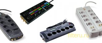
Digital and mechanical potentiometers: differences
The “evolution” of resistors does not stand still. Therefore, it is increasingly rare to find mechanical versions of radio elements in various types of equipment, from amateur radio to devices with LCD displays. They were replaced by digital potentiometers.
Although users note that the functionality of conventional resistors and CPUs is comparable, in terms of technical parameters and reliability, the latter have much higher potential.
CPU and PR are interchangeable resistors with wide resistance ranges. But they also have differences:
- Mechanical potentiometers can withstand large voltage loads and successfully dissipate power. But over time they wear out, and their technical performance deteriorates. Such changes are associated with the design feature of the PR. This does not threaten digital analogues, since they do not have mechanical parts that are the first to wear out, become loose or change shape.
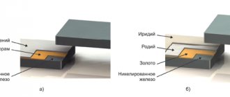
- Mechanical resistors are very sensitive to shocks and shocks, and their moving element can oxidize over time, which also affects their service life. The CPU is made up of multiple IC switches (CMOS), making it resistant to various impacts such as shock, environmental changes, wear and tear, and more.
So it makes sense that all kinds of modern electronic devices have digital potentiometers built into them.
RESISTORS
We continue our series of reference materials for beginner radio amateurs, and in this article we will talk about resistors; they are present in any electronic circuit, even the simplest one. They are divided into two types: variable and constant. Common fixed resistors used in electronic circuits range from 0.125 to 2 watts. To be more precise, this is a series of 0.125 W, 0.25 W, 0.5 W, 1 W, 2 W. Of course, there are more powerful resistors, such as wirewound resistors, but they are rarely used in electronic circuits. The figure below shows the appearance and dimensions of resistors, as well as their designations on circuit diagrams.Schematic designation of fixed resistors
Of these, resistors with a power of 0.125 to 0.5 Watt are most often used in electronics. Resistors can be either ordinary, with a tolerance of 5-10%, or precision, with a tolerance of 0.1-1%. More precise resistors exist, but most amateur radio designs do not require such precision. If a resistor can change its resistance, it is called variable (or tuning). Photo of variable resistors:
Variable resistors
Variable resistors also come in wire and non-wire types; wire resistors are usually designed for higher power. The structure of a non-wire variable resistor can be seen in the figure:
Variable resistor design
The resistor is designed as follows: on a base made of getinax in the form of an arc, a layer of soot mixed with varnish is applied. This resistor has a constant resistance between the first and second contacts (in the figure), in other words, between the outer terminals, but between the middle and outer terminals it changes when the resistor handle is rotated. Adjacent to this resistive layer is a movable contact connected to the central terminal. Very often, with intensive use of the regulator, this layer of soot wears off, and the resistance of the resistor, when the resistor knob is rotated, changes abruptly, sometimes becoming even greater than the maximum set at nominal value. Because of this wear, rustling and crackling noises occur from the speakers, and sometimes, with severe wear, the sound disappears completely. Variable resistors can be either single or double; double ones are usually used in devices with stereo sound. Variable resistors also include trimming resistors:
Trimmer resistor
They differ from standard variables in the absence of a handle and are adjusted by rotating the shaft with a screwdriver. Variable resistors are also single-turn and multi-turn. Schematic representation of a variable and trimmer resistor in the figure below:
Schematic representation of a variable resistor
On Soviet MLT resistors the resistor value was written, on imported resistors the marking is carried out by applying multi-colored rings, in the first two rings the value is encoded, the third ring is the multiplier, the fourth ring is the tolerance of the resistor (for ordinary non-precision resistors).
Color coding of resistors
There are markings with more than four rings; the following figure will help you decipher the markings:
Precision resistors color coding
Sometimes there is a need to find out the value of a resistor, but for some reason it is difficult to do this by color marking. In this case, you need to refer to the circuit diagram of the device. In such diagrams, the resistor value is indicated as follows, for example: 150 means 150 Ohms (units of measurement are not indicated), 100 K means 100 KiloOhms, 2 M means 2 MegaOhms. Sometimes, when assembling a circuit, the required value is not at hand, but there are many resistors of other values; in this case, connecting resistors in series or parallel can help. Everyone knows the calculation formulas from physics textbooks, but if anyone has forgotten, I will give them here:
For serial connection
In parallel connection
Recently, many have been switching to SMD parts, the most common of which are resistors of sizes 0805 and 1206. Determining the value of an SMD resistor is very simple, the first two digits indicate the resistance of the resistor, the third digit is the number of zeros. Example : the marking is 332, this means 33 plus two zeros, it turns out 3300, that is, 3.3 KiloOhms. Less common in electronics, but nevertheless used are thermistors and photoresistors. The figure below shows a schematic representation of thermistors:
Thermistors schematic illustration
For thermistors, the resistance depends on temperature. If the resistance of the thermistor increases with increasing temperature, then the temperature coefficient of resistance of the TCR is positive, but if the resistance decreases with increasing temperature, then the TCR is negative. The thermistor is shown in the photo below:
Thermistor photo
The following figure shows a photoresistor, as it is drawn in the diagrams:
Photoresistor schematic illustration
It is a semiconductor device whose resistance changes under the influence of light.
Photoresistor - appearance
Photoresistors are especially widely used in automation devices. Here is a typical circuit diagram for connecting a semiconductor photodetector:
Typical circuit of a semiconductor photodetector
In general, a resistor can be safely considered the building block of any radio circuit, since it is the most common element in radio electronics.
AKV was with you .
Details forum
Forum for discussing the material RESISTORS
ELECTROLYSER FOR PRODUCING HYDROGEN
Review of a Chinese device for electrolysis of water - photos, videos, description of work.
We are converting a regular tractor toy into a radio-controlled one - photos of the process and the resulting result.
What are OLED, MiniLED and MicroLED TVs - a brief overview and comparison of technologies.WIRELESS POWER CAPABILITIES
About the use of wireless power technology for various devices.
What to consider when choosing a CPU
If you need to buy a digital potentiometer, you should know what parameters to pay attention to. Among them:
- Input signal level (voltage).
- Maximum power and current.
- Impedance (a measure of total resistance).
- Resolution level.
- Number of channels.
- Linearity of resistance.
- Power-on position.
- The presence or absence of volatile memory.
- Resistor interface.
- Device size.
Preference should be given to the CPU whose parameters are most suitable for a specific task. For example, the latter indicator is extremely important for applications and circuits that are critically limited in size. Although some users note that it is possible to make such a potentiometer with your own hands, such work is not worth the time and effort. There is such a large selection of CPUs on sale, and at an affordable price, that you can choose one for any purpose and device.
Main CPU parameters
The most important indicator of this type of resistor is the number of steps, that is, switched taps. It is most often referred to as a power of 2. The most common CPUs are from 32 to 256 steps.
Also, when choosing a device, impedance is considered an important parameter. On sale you can most often find resistors with values of 10 kOhm, 50 kOhm and 100 kOhm.
You also need to pay attention to the maximum voltage at the terminals in the extreme position, look at the level of permissible current, nonlinearity, temperature coefficient and power dissipation.
Device performance may vary between different manufacturers, so it is better to select based on the needs of the equipment for which they are used. Below is a table with the parameters, characteristics and features of potentiometers.
Basic parameters of variable resistors
The parameters of variable resistors can be divided into two groups: parameters common to fixed resistors and special parameters characteristic only of variable resistors.
Parameters common to fixed resistors:
- Nominal resistance (nominal);
- Permissible deviation from the nominal value;
- Rated power dissipation;
- Temperature coefficient;
- Self-noise level;
Special parameters for variable resistors:
- Functional characteristics
- Resolution
- Minimum resistance
- Wear resistance
Functional characteristics
Functional characteristic (taper) – dependence of the resistance of a variable resistor on the position of the moving contact. The functional characteristics of a variable resistor are:
- linear;
- nonlinear.
Variable resistors with a nonlinear characteristic are usually used in audio equipment to adjust the volume level, timbre, etc. The most widely used nonlinear characteristics are:
- logarithmic;
- inverse logarithmic.
A - linear (linear), B-logarithmic (Reverse Log, Reverse Audio), B-reverse logarithmic (Logarithmic, Audio)
It is worth noting that the designation of functional characteristics in domestic documentation differs from foreign ones: the inverse logarithmic characteristic in foreign documentation is designated as Logarithmic.
Resolution
Resolution is the minimum change in resistance with minimal movement of the control knob. This parameter is applicable only to wirewound potentiometers and is determined by the resistance between adjacent turns. Non-wire potentiometers have very high resolution and are determined by defects in the resistive layer.
Minimum resistance
Minimum resistance - resistance in the extreme position of the control knob.
Wear resistance
Wear resistance is the ability of a potentiometer to maintain its parameters during operation. As a rule, it is expressed by the number of cycles of movement of the contact assembly during which the characteristics of the potentiometer remain within the specified limits.
Pros of digital potentiometers
If we compare mechanical or other types of resistors with their digital counterparts, the latter have a number of advantages. Among them:
- Digital potentiometers do not contain moving mechanical elements, which require special adjustments and lose accuracy when impacted.
- The CPUs are highly reliable. They are not afraid of vibration or noise waves.
- Digital resistors operate successfully in low current conditions.
- The electronic potentiometer does not have special holes for adjusting settings, which in conventional devices need to be opened with a screwdriver.
- CPUs are quick to set up.
- They are distinguished by precision of adjustment.
- At power-up, the original CPU position can be loaded from volatile memory.
- You can use several digital potentiometers built into one housing. In this case, the relative deviation in the indicators will be no more than 1%.
- The dimensions of digital resistor housings are very small, which allows them to be used in memory cards for computers, laptops, TVs and other equipment, for example, PCMCIA or similar. Most often these are thin small-sized packages (TSSOP) or SOT-23.
- The price of the CPU is lower than the best versions of variable resistors.
All these parameters determine the choice of consumers and manufacturers of electronic equipment in favor of digital potentiometers.
Availability of non-volatile memory
This is a very important parameter. Simple variable resistors, after adjustment, retain the adjustment parameters. For digital ones, everything is different: as soon as the shutdown occurs, the specified settings are reset. The next time the CPU is connected, it returns to the position originally entered (factory settings, for example). The initial parameters depend on the type of resistor.
In a system with a digital potentiometer, a microprocessor is often installed that can load the codes necessary to restore the adjustments. If it is not available, a resistor with volatile memory should be used.
This built-in function allows you to set the necessary parameters once, and restore them the next time you turn off/on the device. Today, most manufacturers, such as Catalyst or Xicor, make CPUs exclusively with programmable memory.
There are even digital resistors with the ability to remember up to 4 settings, which is very useful if the device operates in several modes at once or under preset conditions. The amount of memory may vary depending on the purpose of the CPU. Thus, the DS1845/46 resistor has a memory of 256 B.
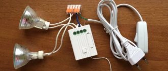
Remote controlled variable resistor
The Radiochipi website shows a diagram of a device that functionally replaces a variable resistor. The functional analogue of a variable resistor here is a circuit based on a D2 multiplexer of type K561KP2 and a set of fixed resistors R1R7. The K561KP2 multiplexer is a set of eight switches made using MOS technology, some channel pins of which are combined into pin 3, and the opposite ones into separate pins. The channels are such that they act like a "solid state relay" and can carry both analog and digital signals.
In practice, K561KP2 is an eight-position switch, controlled using a three-bit binary code supplied to its control inputs. In this case, the “horseshoe” of the analogue of the variable resistor is represented by resistors R1R7 connected in series, and instead of the “slider”, pin 3 of the multiplexer D2 works. The difference from a conventional variable resistor is that here the adjustment is not smooth, but in eight fixed positions.
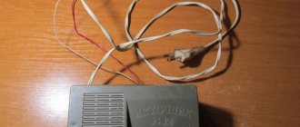
For remote control, a circuit is used on the D1 microcontroller type PIC12F629, which contains a decoder of the volume control commands “VOL+” and “VOL” sent by a standard remote control operating using the RC5 protocol. When you press the “VOL+” and “VOL” buttons of the RC5 remote control, the binary code at the output formed by ports GP0, GP1 and GP2 changes sequentially from “000” to “111” in one direction or the other (depending on the adjustment to decrease or increase) . The remote control signals are received by photodetector FP1.
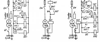
When using such a “variable resistor” you need to know that the voltage under which it may be located should not exceed the supply voltage of the microcircuit, that is. 5V. Figure 2 shows a variant of using such a circuit to adjust the volume in a stereo ULF. A double “variable resistor” is made here, so another multiplexer is used for the second stereo channel. The equivalent resistance of the “variable resistor” is 2×70 kOhm.
The principle of a dual variable resistor is implemented. turned on by a potentiometer that regulates the voltage of the input signal from connector X1 passing through a “variable resistor” to connector X2. “Variable resistor” with a linear regulation law. But by changing the resistance of individual resistors from R1R14, you can organize almost any regulation law. A negative voltage of 5V is applied to pins 7 D2 and D3. The fact is that the most linear section of the IC channels is body voltage.
As a result, the keys are under a voltage of 10V, and the AF zero lies at the +5V point. At the same time, the channels themselves are not under any bias voltage. Figure 3 shows a diagram of a switch with 8 fixed settings for a VHF receiver made on the same principle.
K561KP2 is in a zone somewhere in the middle between positive and negative voltage. Since the audio signal voltage is usually low, in order to prevent distortion, a negative voltage is applied to pin 7 (minus the keys’ power supply). As a result, the keys are under a voltage of 10V, and the AF zero lies at the +5V point. At the same time, the channels themselves are not under any bias voltage. Figure 3 shows a diagram of a switch with 8 fixed settings for a VHF receiver made on the same principle.
Permissible stress range
A special feature of digital potentiometers is that they cannot be connected to a circuit whose voltage is higher than the permissible voltage for them. This parameter should not exceed the CPU voltage. For most digital resistors on the market, this ranges from 0 to 5 V. The CPU can only be used in circuits with the same supply voltage.
True, there are options, the voltage at the terminals of which is greater than in the power supply. Thus, the X9312 electronic potentiometer has a +5 V supply, but is capable of accepting +15 V.
There are also resistors with bipolar power supply, for example, ±5 V. As some users note, bipolar power, when supplying control signals with a relatively negative voltage, can also be supplied to a regular CPU.
RESISTORS | Resistor markings
Resistors are among the simplest, in terms of understanding and design, radio-electronic elements. However, they occupy a leading position in their use in circuits of various electronic devices. Therefore, it is very important to learn how to use them for practical purposes, to be able to independently calculate the necessary parameters and choose the right resistor with the appropriate characteristics. This article is devoted to these and other issues.
The main purpose of resistors is to limit the amount of current and voltage in an electrical circuit in order to ensure normal operation of the remaining electronic components of the electrical circuit, such as transistors, diodes, LEDs, microcircuits, etc.
The most important parameter of any resistor is resistance. It is due to the presence of resistance that it becomes more difficult for electrons to move through an electrical circuit, as a result of which the amount of current decreases. In view of this, resistance not only plays a positive role - it limits the current flowing through other radio-electronic elements, but is also a parasitic phenomenon - it reduces the efficiency of the entire device. Parasitic resistance includes resistance of wires, various connections, connectors, etc. and they are trying to reduce it.
The discoverer of such a property of an electrical circuit as resistance was the outstanding German scientist Georg Simon Ohm, therefore the Ohm . The most practical applications are kilo-ohms, mega-ohms and giga-ohms.
An extended list of SI abbreviations and prefixes for physical quantities used in radio electronics. The maximum value is 1018 - exa, and the minimum - 10-18 - atto. I hope the table below will be useful.
Conventionally, resistors are divided into two large subtypes: constant and variable.
Fixed resistors
Fixed resistors can have different designs, mainly differing in appearance and size. A characteristic feature of constant resistors is a constant resistance value, which is not intended to change during the operation of electronic equipment.
Trimmer resistors
Trimmer resistors are used to fine-tune individual components of radio-electronic equipment at the stage of its final adjustment before putting it into operation. Most often, trimming resistors do not have a special adjustment handle, and changing the resistance is done using a screwdriver, which prevents spontaneous changes in the position of the adjustment unit, and, accordingly, the resistance.
In some devices, after final adjustment, paint is applied to the housing and the rotary screw of the trimming resistor, which prevents the screw from turning in the presence of vibrations. Also, the mark applied with paint also serves as an indicator of spontaneous rotation of the adjusting screw, which can be visually determined by the paint peeling off in the place of the rotary and stationary elements of the housing.
In modern electronic devices, multi-turn trimming resistors are widely used, allowing for more precise adjustment of the equipment. As a rule, they have a blue plastic body with a rectangular shape.
Variable resistors
Variable resistors are used to change the electrical parameters in the device circuit directly during operation, for example, to change the brightness of LED lamps or the sound volume of the receiver. Often, instead of “variable resistor” they say potentiometer or rheostat.
Variable resistors also include radioelements that have only two terminals, and their resistance varies depending on illumination or temperature, for example photoresistors or thermistors. Potentiometers are used to change the amount of current or voltage. The adjustable parameter depends on the switching circuit.
If a variable or tuning resistor is used as a current regulator , it is called a rheostat .
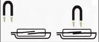
Below are two circuits in which a rheostat is used to regulate the amount of current flowing through a VD LED. Ultimately, the brightness of the LED changes.
Please note that in the first circuit all three terminals of the rheostat are involved, and in the second - only two - the middle (regulating) and one extreme. Both circuits are fully operational and perform the functions assigned to them. However, it is less preferable to use the second circuit, since the free terminal of the rheostat, like an antenna, can “catch” various electromagnetic radiation, which will entail a change in the parameters of the electrical circuit. It is especially not recommended to use such an electrical circuit in amplifier stages, where even minor electromagnetic interference will lead to unpredictable operation of the equipment. Therefore, we take the first scheme as a basis.
You can change the voltage value using a potentiometer according to the following scheme: two outer terminals are connected in parallel to the power source; between one extreme and middle terminal, you can smoothly regulate the voltage from 0 to the voltage of the power source. In this case, from zero to 12 V. The potentiometer serves as a voltage divider, which is discussed in more detail in a separate article.
Conventional graphic designation (UGO) of resistors
In drawings of electrical circuits, regardless of the appearance of the resistor, it is designated by a rectangle. The rectangle is signed with the Latin letter R with a number indicating the serial number of this element in the drawing. Below is the nominal resistance value.
In some countries, the UGO of the resistor has the following form.
Resistor power dissipation
A resistor, like any other element with active resistance, is subject to heating when current flows through it. The nature of heating is that when moving, electrons encounter obstacles in their path and hit them. As a result of collisions, the kinetic energy of the electron is transferred to the obstacles, which causes heating of the latter. A nail heats up similarly when it is hit for a long time with a hammer.
Power dissipation is a normalized parameter for any resistor and if it is not maintained, it will overheat and burn out.
Power dissipation P depends linearly on resistance R and squared on current I
P=I2R
The permissible P value shows how much power the resistor can dissipate without overheating above the permissible temperature for a long time.
Generally, the higher P is, the larger the resistor is to remove and dissipate more heat.
On the drawings of electrical circuits, this parameter is applied in the form of certain marks.
If the rectangle is empty, then the power dissipation is not standardized, so you can use the “smallest” resistor.
More visual examples of calculating P can be found here.
Accuracy classes and resistor values
Not a single radio-electronic element can be manufactured with one hundred percent compliance with the required characteristics, since accuracy is associated with a number of parameters and technological processes, which have an inherent error, mainly associated with the accuracy of production equipment. Therefore, any part or individual element has a deviation from the specified dimensions or characteristics. Moreover, the smaller the spread of characteristics, the more accurate the production equipment and the higher the final cost of the product. Therefore, the use of products with minimal deviations in characteristics is not always justified. In this regard, accuracy classes have been introduced. In amateur radio practice, resistors of three accuracy classes are most used: I, II and III. Recently, resistors of the second and third accuracy classes are quite rare, but we will consider them as an example.
Class I includes tolerance for resistance deviation from the nominal value of ±5%, Class II – ±10%, Class III – ±20%. For example, with a nominal resistance value of 100 Ohms of a class I resistor, the permissible deviation can be in the range of 95...105 Ohms; for II – 90…110 Ohm; for III - 80...120 Ohm. Resistors of a higher accuracy class, with a tolerance of 1% or less, are classified as precision. They have a higher cost, so their use is justified only in measuring and high-precision technology.
All standard resistance values of I…III accuracy classes are given above in the table, the values from which can be multiplied by 0.1; 1, 10, 100, 1000, etc. For example, class I resistors are manufactured with values of 1.3; 13; 130; 1300; 13000; 130000 Ohm, etc.
Depending on the accuracy class, the nominal values of industrially produced resistors are strictly standardized. For example, if you need a resistance of 17 Ohms of class I, you will not find it, since this value is not manufactured in the appropriate accuracy class. Instead, you should choose the closest rating - 16 Ohms or 18 Ohms.
Resistor markings
The marking of resistors serves to visually perceive a number of parameters characteristic of these electronic elements. Among other parameters, three main ones should be highlighted: nominal resistance value, accuracy class and dissipation power. It is these parameters that first of all pay attention to when choosing the radioelements under consideration.
For many years, there were many types of markings, but gradually, as technological processes developed, a couple of types of markings supplanted all others.
The housings of Soviet resistors, which are still widely used, are marked with numbers and letters. The Latin letters “E” and “R” next to the numbers or just the numbers indicate resistance in ohms, for example 21; 21E, 21R – 21 Ohm. The letters "k" and "M" stand for kilo-ohms and mega-ohms, respectively. For example, if a letter stands before or in the middle of numbers, then it simultaneously serves as a decimal point: 68k - 68 kOhm; 6k8 – 6.8 kOhm; k68 – 0.68 kOhm.
Color coding of resistors
Most radio-electronic elements are now color coded. This approach is quite rational, since colored marks are easier to see than numbers and letters, and therefore are well recognized even on the smallest cases.
Color markings of resistors are applied to the housing in the form of four or five colored rings or stripes. In the first case (4 stripes), the first two stripes denote the mantissa, and in the second (5 stripes), the mantissa is denoted by three stripes. The third or 4th ring, respectively, indicates the multiplier. The fourth or fifth is the permissible deviation as a percentage of the nominal resistance.
In my opinion and personal experience, it is much more convenient, simpler and more practical to measure resistance with a multimeter. This is where there is the least chance of making a mistake, since the colors of the rings are not always clearly distinguishable. For example, the color red can be mistaken for orange and vice versa. However, when performing measurements, you should avoid touching the multimeter probes and resistor leads with your fingers. Otherwise, the human body will bypass the resistor, and the measurement results will be underestimated.
Marking of SMD resistors
A characteristic feature of SMD resistors compared to output analogs is their minimal dimensions while maintaining the necessary characteristics.
SMD components do not have flexible leads; instead, there are contact pads through which SMD parts are soldered onto similar surfaces provided on the printed circuit board. For this reason, SMD components are called surface mount components.
Thanks to the replacement of the traditional housing with SMD, the process of automating the manufacture of printed circuit boards has been simplified, which has significantly reduced the time spent on manufacturing an electronic product, its weight and dimensions.
The marking of SMD resistors most often consists of three numbers. The first two indicate the mantissa, and the third indicates the multiplier or the number of zeros following the previous two digits. For example, the marking 681 means 68 × 101 = 680 Ohms, that is, after the number 68 you need to add one zero.
If all three digits are zeros, then this is a jumper; the resistance of such an SMD resistor is close to zero.
More articles on this topic
- Calculation of a resistor for an LED
- Connection of resistors
- Capacitors | Operating principle and marking of capacitors
- Zener diode | Operating principle and marking of zener diodes
Possible interference
They may appear due to the fact that extraneous signals from the control inputs to the circuit penetrate into the CPU. This occurs due to the presence of capacitances in them, for example, between channels or the gate of a field switch.
Such interference is practically unnoticeable where adjustments are rarely made, but, for example, when setting the volume, they are undesirable. For devices where the CPU must be tuned, special electronic resistors are often needed to eliminate such interference, for example, glitchless regulators.
Areas of application of CPU
The area of use of digital potentiometers is very wide and is becoming larger every year, because new, more “advanced” resistors appear. Below are the most common applications of CPUs:
- In digital (electronic) amplifiers. These devices are used to amplify electrical power.
- In reference voltage sources. IONS are installed in all measuring instruments and are their main component. The digital potentiometer in their circuit ensures accurate settings.
- In volume control systems in any acoustic devices.
- In operational amplifiers (op-amps) to bias the voltage towards zero.
- In voltage stabilizers to regulate it.
- In devices or circuits for measuring the resistance level of electric current to configure bridges.
- For setting the frequency, adjusting the gain or attenuation of sound in bandpass filters. The CPU is required to calibrate the oscillation system.
- In measuring instruments with signal amplification sensors to adjust the full scale and its offset.
- In pulse generators with an asymmetrical type of signal to regulate their frequency.
- In wideband adjustable RF attenuators for regulating Pin diodes. The latter are responsible for protecting radio equipment from unwanted microwave pulses.
- In LCD indicators for adjusting contrast.
Most often, CPUs are used as volume adjusters in smartphones, multimedia, and small portable equipment. There are dedicated CPUs available for use in high-end regulators, such as the CS3310 from Crystal or the AD7111 from Analog Devices.
Examples of using
Below is an example of how to use and control the AD5206 6-channel CPU using an Arduino board. The device is designed to regulate the brightness of diodes. This uses SPI communication. To configure resistors you need:
- Arduino board.
- AD5206 CPU.
- LEDs (6 pcs.).
- Jumpers and breadboard.
Below is a diagram of the AD5206, its pinout and pin assignments.
This digital potentiometer is equipped with 6 variable resistors, for each of which there are 3 pins in the case. For individual potentiometers, the pins are labeled A1, B1, and W1.
In this example, all 6 potentiometers are used as a voltage divider. Why is 1 outermost pin (A) connected to the power supply, and the second (B) to the ground bus. Wiper (or medium) takes the changing voltage.
When connected this way, the AD5206 produces a resistance of 10 kOhms that varies in 255 steps.
Below is the connection diagram.
I was wondering if it was possible to make a variable resistor controlled by electricity (at home).
Immediately a search showed that this is either an electronic switch for a set of resistors or it is proposed to use a transistor.
Options with a bipolar transistor were considered, but nothing useful came of it and I came across the article “A simple circuit for replacing a variable resistor with two buttons (KP301, KP304).” And the article describes the circuit of a variable resistor on a field-effect transistor.
The diagram looks like this:
KP304 is used as a transistor. I didn’t have this and decided to use what I had at hand to test and simulate the circuit - IRF5305, IRF510 or IRF530N. The first transistor is P-channel, quite suitable for replacing the KP304, but the second two are N-channel and the circuit will need to be redone.
It just became interesting to understand how the circuit works, simulate it and convert it to work with an N-channel transistor.
The circuit was converted to this form; resistors were selected at random for now. They affect the charging and discharging time of the capacitor.
I have R16 resistor 1 MOhm on the circuit (10K Ohm on the original) and R17 I have 1 MOhm (on the original 8.8 MOhm). The approximate operation of the circuit is that when you press the bottom button along the chain: Vpit-C12-R17-Button-GND, charging occurs. At this moment, the voltage at the transistor’s gate begins to change; when a threshold level is reached in relation to the source, the transistor begins to open, changing its resistance. The voltage divider at the output of the circuit (between R22 and R24) begins to be affected by the resistance of the transistor and the voltage at the junction of the transistor and resistors begins to change.
At the moment, if you release the button at the bottom and press the top button, the charge accumulated by the capacity will begin to be spent on the chain: C12-R17-Button-R16-C12. That is, a power source without ground now no longer powers the circuit, and the capacitor becomes the power supply.
I'll try to model it in LTSpice:
In the program, the resistor values were changed to 500,000 Ohms, because the large value of the R17 resistor did not give a fast enough charge increase and the simulation failed. This is what the assembled diagram showed:
The blue line is the gate voltage relative to ground. The red line is the voltage at the divider output relative to ground and the green and blue lines are simulations of pressing a button. As long as the lines are above 0V, the button is pressed.
You can see from the graph that the voltage at the gate changes and the resistance of the transistor changes. The change is quite smooth.
Now I'll try to change the circuit for the n-channel transistor IRF510 or IRF530N.
This is what the diagram will look like:
I got rid of the divider for now, because I want to check in a simplified form how the transistor will behave. I changed the connection between power and ground.
Here is a diagram in LTSpice; to track transient processes, I changed the resistance of the resistors to 5000KOhm.
Here is the resulting diagram:
and immediately started modeling:
The blue line is the gate voltage relative to ground. The green line is the voltage drop across the SI transistor. The blue and red lines are an imitation of turning on the buttons.
Wow, the simulation showed that the transistor model has a high transconductance. The transistor literally changed its resistance with a jerk within the minimum period of voltage change at the GR (gate-source).
Here is the second graph, where the green line is the gate-source difference. It can be seen that when the voltage reaches 3.7V, the transistor is unlocked and the entire voltage drops across the 100 Ohm resistor.
The next step is to return the divisor. Here's the diagram:
Resistors for the experiment are 50KOhm. And here is the simulation - the output of the circuit is the connection point between the divider R3 and R4 and the output of the transistor.
The jump is no longer as sharp as in the example below - a circuit without a divider with resistances of 50KOhm:
And now let’s increase the resistor values to 1 MOhm:
and modeling:
Now there are gentle slopes, just like in the circuit with the P-channel transistor TRF5305.
And a comparison of the simulation of two circuits on top with a divider and on the bottom without a divider and 1 MΩ resistance:
The top pattern is smooth. Those. The circuit has been converted and is working.
Below is a video with modeling and assembly of circuits on a breadboard and measurements with a photocillograph.
The resistor value in the actual circuit had to be increased to 5 MΩ.
CPU for circuit programming
When digital potentiometers are used to program various levels in circuits or for calibration in sensor devices, it is their state that determines the speed and accuracy of adjustment when connected to power.
There are many different types of CPUs on sale, differing in their ability to customize the power-on state, but there are only two main categories:
- Non-volatile crystal resistors that have a memory element. It is the latter that fixes the position of the engine when the device is connected.
- Energy dependent. These types of CPUs do not have memory, so in them the engine takes the position zero, middle or top when connected to power, depending on their design. To install it correctly, you should study the instructions with technical parameters.
The first versions of the CPU can be divided into 3 types according to the type of memory they use:
- Electrically erasable or reprogrammable (EEPROM). Data in them can be erased and rewritten an unlimited number of times.
- With a one-time program.
- Multiple programmable.
This division helps to select the optimal type of potentiometer for a specific circuit or system. So, in equipment where constant (frequent) adjustment is required, for example, the sound in an audio system, you can install a volatile option.
If you need to configure the parameters of the device once for its use, for example, factory settings, then the type with ORT is suitable. It remains unchanged for the entire duration of its operation.
A digital potentiometer can only accept the signal amplitude that is within its upper and lower supply voltage. If you plan to use it to conduct alternating current, then it is better to use resistors with bipolar power supply.
Variable resistor series
With the introduction of GOST 13453-68, an alphanumeric system of abbreviated notations began to be used, depending on the group and properties of resistors. The letters indicate the product group:
- C – constant resistors;
- SP – variable resistors.
The number indicates the type of resistor depending on the manufacturing technology and material:
- 1 – non-wire thin-layer carbon and boron carbon;
- 2 – non-wire thin-layer metal film and metal oxide;
- 3 – non-wire composite films;
- 4 – non-wire composite volumetric;
- 5 – wire;
- 6 – non-wire thin-layer metallized.
After the first digit, a hyphen is followed by a second digit(s), which indicate the registration number of a specific type of resistor. For example: SP3-3, SP5-22.
Since 1980, the designation of resistors has been carried out in accordance with OST 11.074.000-78. The resistor designation consists of three elements:
- First element: a letter or combination of letters to designate a subclass (P - constant resistors, RP - variable resistors, NR - sets of resistors);
- Second element: a number indicating a group of resistors according to the material of the resistive element (1 – non-wire, 2 – wire and metal foil);
- The third element is the registration number of the specific type of resistor.
For example: RP1-54.