An ordinary soldering iron: we study and bring it back to life
This little note came about by chance that happened yesterday morning. As always, the cyclone had nothing to do at first light, and he decided to volt-modify something that first caught his eye. That something was destined to be the 7600GS video card from EVGA. But, as you know, the law of meanness not only does not sleep, but does not even sleep. Not just in the morning, but in general. Therefore, as soon as the author of these lines took out the soldering iron, it is unclear how he managed to “drop” it for the first time in his life - only the tail remained in his hands, that is, the power cord with a plug. You understand, the quality of our things, incl. the hero of these lines sometimes leaves much to be desired. It was decided not to forget about the voltmode, because a real overclocker should always have at least two soldering irons :). But, nevertheless, the loss of a beloved friend of domestic production hit hard on the unawakened psyche, therefore, it was urgently decided to place the fresh “corpse” in intensive care and save his life. How this happened and how it ended - read on.
But now - a small introduction to the matter. I think most of you know what a soldering iron is and have held it in your hands at least once. However, those who are familiar with the structure of such a device are probably much smaller. A soldering iron is an indispensable tool for a real Overclocker, because it is impossible to overclock a video card to the limit or improve the overclocking potential of the motherboard without modifying their power systems, and in the vast majority of cases, a pencil will not do the job. As for the breakdown of soldering irons, situations similar to those described above are not uncommon. Sometimes a not very high quality, but at the same time inexpensive subject just falls apart while soldering. Of course, if an unpleasant situation occurs, someone will prefer to buy a new “voltmodder’s main tool.” But there is a certain category of people for whom doing something with their own hands is a hobby, and there are also those for whom the equivalent of 3 dollars is an expense not provided for by the party for the current five-year plan. It is to these people that this guide is primarily dedicated to bringing back to life a soldering iron whose power cord accidentally or not completely broke or for some other reason the contact of the wire with the heating element was lost. Along the way, everyone will also be able to get acquainted with the internal structure of a seemingly simple, but at the same time so interesting device.
To carry out the “reanimation” operation we need several ingredients:
- soldering iron with a torn power cord – minimum 1 piece, maximum unlimited;
- Chinese multimeter or Soviet tester - without any preference;
- straight arms – preferably 2 pcs;
- head on shoulders – 1 piece;
- curved convolutions - the number is selected individually.
Before we begin, I have to remind you: everything you do is done at your own peril and risk.
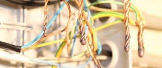
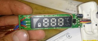
Neither the author of these lines nor the site administration are liable in the event of failure of any components associated with the modification, or injury of varying degrees to those who decide to repeat the recommendations described on this page. Remember: the soldering iron operates on 220V AC power, and any, even the smallest mistake can lead to irreversible consequences! Strictly follow safety regulations when repeating the described modifications and generally when working on devices that are powered by AC power! As always, we scared off the indecisive, warned the inattentive - you can get down to business with a clear conscience! Let me remind you that we have in our hands a soldering iron with a torn off power cord. Tasks for the next half hour: a) get acquainted with the internal structure of the hero of the review; b) if possible, bring him back to life. The first thing we do is remove the handle made of heat-resistant plastic. What remains in your hands is – let’s call it that – a “casing”, in which all the patient’s insides are actually located. We unscrew the only bolt - two or three turns allow you to fix or release the rod, which actually does the soldering, and its complete separation from the thread allows you to remove the “cartridge” for the rod. On the other side of the “casing” we bend two antennae and first carefully take out two thin tubes about 4 cm long, metallic in color, and behind them is the heating element itself - a tube of the same type of larger diameter and length, in which a metal spiral with high resistivity (most likely nichrome). As you can see, the contacts of our spiral remained intact - great news. To ensure the integrity of the heating element, you can measure the resistance between the contacts. For a 25W soldering iron, it resists approximately 2kOhm +/-100Ohm. Here is everything that any standard soldering iron consists of: The next step is to connect the contacts of the spiral to the power cord. Don’t forget that you first need to “put” a soldering iron handle and a white heat-shrinkable tube on the cord, and on each wire - small tubes that serve to isolate one contact from the other (although they look like metal, in fact they do not conduct current, it’s easy crumble, peel off. In addition, they are not afraid of high temperatures). You can cheat - connect the wires somehow, but in this case it is possible that the patient will soon get sick again, so it’s better to overdo it. It turns out? Then everything is simple - we put our insulating tubes on the exposed wire, slide a white polyvinyl chloride heat-shrink tube closer, and place the whole thing in the “casing” of the heating element. Since the rod holder and the rod itself have become fairly smoked during operation, I advise you to lightly clean them with fine sandpaper, and additionally flatten the “cartridge” slightly - to achieve better contact and heat transfer from one to the other. We place the cartridge with the rod in the “casing” on the other side and secure it with a screw. Just in case, we check the resistance again, this time between the contacts of the power plug. It shouldn’t have changed, so if it increases, it means you have a bad connection somewhere. If the resistance is close to zero, you have managed to create a short circuit somewhere in this simple circuit. Neither the first option nor the second, of course, are suitable for any real testing and, especially, work. We disassemble the soldering iron again, correct the errors, and reassemble in the reverse order. Is everything okay now? Okay, then you can bend the antennae of the heating element “casing”... ...and put a plastic handle on it. Just in case, let's also check the resistance between the contacts of the power plug. Now the soldering iron can be plugged into the network with a confident hand. Particularly timid people can hide behind the sofa and turn on the soldering iron through a power extension cord or even a switch in the hallway :). Everything _must_ work. Personally, I succeeded. The whole thing took about half an hour. For the whole day I received a charge of energy from a folk craftsman - you can move to new heights! And in fact, the soldering iron dear to my heart not only came back to life, but even began to heat up faster and solder better - thanks to a decrease in the thermal resistance of the “heating element - cartridge - rod” system! I hope this note will be useful to someone in practice, and in the meantime may nothing ever break or burn for you! Always full of crazy ideas, © cyclone www.modlabs.net
Requirements for modern soldering equipment for 2022
If you are going to solder boards or repair electronics, then the soldering irons and stations are required to:
- Availability of temperature control with stabilization, indication and adjustment functions;
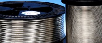
- Various fireproof “eternal” stings in shape and size;
- Sleep and temperature memory functions (so as not to keep the soldering iron constantly on, thereby saving electricity and reducing the load on the tip);
- Good characteristics of temperature stability on the tip.
Currently, not all soldering irons meet the requirements presented. Let's look at popular soldering irons and stations among radio amateurs and electronics engineers.
DIY soldering iron repair
Have you purchased a soldering iron, but are not satisfied with the quality of its work? Then you will find in this article material on how to repair a soldering iron if you do not want to take it to a workshop, but decide to do it yourself. The video tutorial presented is about a cheap Chinese device in which some parts need to be replaced.
Unusual soldering irons are sold cheaply in a Chinese online store.
What you need to remake a soldering iron
- soldering iron; - thick copper wire; - screwdriver; - drill; - wire; - wire cutters; - electrical tape; - fork; - flux; - tin;
- metal sponge.
Refinement of the Chinese soldering iron
The first thing we will pay attention to is the ineffective soldering iron tip; we will replace it with a copper wire of the required diameter. Let's take out the old tip and make it out of copper to the same size (thickness and length).
To refine the working end of the sting, the author of the video used a drill. It is enough to have a good file and all work with the tip of the tip will be done just as well.
Next, we’ll replace the worthless Chinese cord with a high-quality one. You should not take risks with a fairly energy-intensive tool, like a soldering iron, to avoid overheating of the wire and insulation.
All that remains is to tin the tip and you can solder with the normal soldering apparatus you have modified.
Notes
Another disease of Chinese soldering irons is severe overheating during operation. It can be eliminated by inserting into the gap one of the wires a diode with an operating voltage of at least 300 volts (it can be mounted in a power plug; the polarity of the connection does not matter). In order for the soldering iron tip to burn less, before work it must be forged in a cold state with a small hammer; in this case, the copper becomes denser and does not burn so quickly.
izobreteniya.net
Conditional separation of instruments
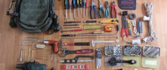
All tools (no matter for what job) can be divided into three conditional groups:
- Tools that require experience to operate. They do not tolerate mistakes, and give a false idea of the craft;
- Tools that don't require much experience. They will help you learn this or that job, and tolerate the mistakes of beginners;
- Professional tools that are too good for beginners. They require a lot of experience to realize their rich potential in work, but can also help in training.
Now let's look at examples of soldering irons and soldering stations.
How to make a soldering iron with your own hands: 4 different ways
Making a small electric soldering iron at home is not particularly difficult. A soldering iron is a very necessary and useful tool for all home craftsmen who love crafts and DIY things. Of course, such a device can be purchased at an electrical goods store, but it costs money. Masters of their craft can try to make such a tool on their own, especially if the work requires a specific unit.
Content:
The first soldering iron was invented by Ernst Sachs in 1921. He also patented a hammer tool for tin work.
To make an electric soldering iron, we do not need a huge amount of available tools and materials.
The inside of the soldering iron is simple and consists of the following components:
- Metal tube with handle and sting;
- An electrically insulated heating element (the insulation can be mica or ceramics);
- A current-carrying cord connected to a network or transformer.
Basically, electric soldering irons operate on mains power, a transformer, or batteries. There are types that have a built-in gas burner or conventional external heating.
A low-power electric soldering iron is used for soldering electronic parts and microcircuits, and a powerful one is used for massive, large parts.
Types of soldering irons:
- Nichrome - have a nichrome wire spiral that passes current;
- Ceramic - consists of ceramics, heats up quickly, but, unfortunately, such a heater is very difficult to repair after a breakdown;
- Induction – heating occurs using an induction coil;
- Pulse (spot) – works in the mode of pressing and holding the start button;
- Gas – stand-alone cordless soldering iron that can be used anywhere;
- Battery - this type is usually low-voltage, having low power (usually about 12 v or 15);
- Infrared – heated by infrared radiation with a wavelength of 2-10 microns;
- Ultrasonic – used where it is difficult to solder aluminum using conventional methods;
- A soldering iron heated over an open fire is a fairly simple device that sometimes replaces a high-power device.
The most common are network devices powered from a 220V network. Sometimes, when assembling industrial electrical appliances, an entire soldering station is used, with which you can use additional capabilities.
It is also worth noting a blowtorch, in which heat is released when flammable substances burn. It is used to heat elements, melt solder and warm up other soldering irons.
By the way, soldering irons are now starting to appear in games like Minecraft. To make it there, you need to add a bucket of water, 3 iron ingots and 1 bronze.
Guide: how to make a soldering iron at home from a resistor
The simplest scheme for creating a soldering iron from improvised means is from a resistor. The device will operate at a voltage of 6-24 Volts.
For a soldering iron you will need:
- Resistor PEV or MLT;
- A couple of copper rods of different sections;
- Spring ring, washer, screw;
- Textolite for handle.
It remains to find out the sequence of steps for creating a soldering iron at home.
The manufacturing process is divided into the following stages:
- The end of a thick rod is drilled with a thread for a screw;
- Next, you need to cut out a cavity for the retainer (spring ring);
- The second end is drilled with a diameter like a thin twig (it will act as a sting);
- Then all the parts are assembled into one;
- A soldering iron tip is attached to the resistor at the back and secured with a screw and washer;
- A handle with places for a resistor and wire is made from textolite;
- The power cord is connected to the terminals of the soldering iron.
Homemade pulse soldering iron with your own hands
The principle of operation of a pulse tool is to supply a small current to the tip during soldering, and not constantly. To assemble such a super fast heating soldering iron (for example, Moment), you will have to use a transformer.
To reduce the unnecessary power consumption of soldering tools when they are idle, the pulse soldering iron was developed
What else is needed:
- LED indicators;
- Copper wire;
- Plastic body;
- Stand made of dielectrics;
- On/off button.
The operating principle of a pulse soldering iron is a little more complicated than that of a conventional device with a heating element. To start creating it, you will first have to tinker with the transformer, as well as make calculations and select the wire.
You can use a switching power supply, and in this case the transformer just needs to be slightly altered and rewinded.
This is done like this:
- The secondary winding is removed and rewinding is done using a couple of turns of wire;
- The transformer with a new winding is placed in the prepared housing;
- Instead of a switch, a button to turn on the device is inserted;
- A dielectric stand is mounted, and a copper loop is fixed on it - a thin tip;
- The tip is then connected to the secondary winding of the transformer;
- All that remains is to make the handle.
During operation, you do not need to hold the button in the on state for a long time, as in this case the device may overheat and fail.
DIY battery-powered soldering iron
It’s quite possible to make a battery-powered soldering iron yourself by preparing the necessary materials.
A self-created battery-powered soldering iron helps in repairing wires, cables, equipment and much more where there are no outlets.
To create a battery-powered soldering iron you need:
- Ballpoint pen body;
- Wire made of steel and copper;
- Resistor;
- Textolite double-sided;
- Copper foil and wire;
- Insulating tape;
- Heat-resistant handle;
- Iron tube (can be replaced with a body from a metal ballpoint pen);
- AA or Krona batteries;
- Talc;
- Wire cutters;
- Silicate glue;
- Scissors and stationery knife;
- Newspaper.
Instructions on how to make a cordless soldering iron:
- Work begins with sharpening the copper wire. This can be done on a newspaper with a stationery knife. Sharpening should be continued until the tip of the wire resembles the end of a screwdriver (bevel angle 45 degrees). After sharpening, solder must be applied to the surface, otherwise the uncovered part will burn during operation.
- To create an electrically insulating mass, you need to mix glue and talc to the consistency of liquid sour cream, and then apply it to the sting with tweezers or a plate. This mixture should be very sticky and after applying it to the sting, it should be sprinkled with talcum powder.
- Next, a foil tube is put on the tip. In this case, you need to leave the tip protruding from the tube no more than 1 cm. Next, the heater is covered with a thin layer of insulation and dried. The temperature should be at least 150 degrees, and the mass should become solid. After this, you need to use nichrome wire and wrap it around the sting. Winding is done in a spiral. The ends of the wire must be brought out straight, and the winding must be covered with an electrical insulating mixture and dried again. The turning end is retracted onto the heater and then attached to the tube. Apply the mixture again and dry.
- All that remains is to assemble the device. The ends of the heater are connected to the surface of the batteries. The contacts are insulated and the whole thing ends with a wooden or plastic handle that holds the batteries.
When working with a portable soldering iron, you should always keep a can of compressed air nearby. You will need it to remove dust from microcircuits before soldering.
You can make a model with a power cord. True, in this case you will need a 220/12V step-down transformer unit.
For ease of use, you can make your own stand for the device, the basis of which can be any metal box.
A simple DIY mini soldering iron and device repair
You can create a miniature nano-electric soldering iron at home using a gas lighter or car cigarette lighter. Kind of like a bitch.
What you will need to create a mini soldering iron:
- Gas lighter in a metal case;
- Copper wire;
- File;
- Pliers.
It is better to choose a lighter that has a large fire and the ability to work even in windy weather.
Work algorithm:
- The wire is clamped with pliers and then wrapped onto the lighter box;
- The other end of the wire element is sharpened;
- The sting should be fixed with the same wire in several turns.
A small homemade micro-soldering iron is ready. All that remains is to check its performance and you can solder SMD and other small parts. If the need for such a tool no longer exists, it can always be disassembled and then restored.
What to do if the soldering iron stops working? Most likely, the tip is charred or clogged. An activator will help to repair the part, which will very carefully clean the part from carbon deposits. Moreover, such repairs will not take much time.
Tips: how to make an electronic cigarette from a pen
Instead of regular cigarettes, it has become fashionable to smoke electronic ones, and instead of regular lighters, USB lighters have begun to be used, which serve as a kind of analogue of a car cigarette lighter. It is very easy to charge such a device by connecting it to the USB connector of a laptop or mobile phone. But the problem is that such things are expensive, and not everyone has the money. Therefore, some craftsmen try to assemble a lighter or electronic cigarette at home.
Making an electronic cigarette at home is quite possible.
Warning! Making cigarettes at home can harm your body if you assemble the components incorrectly! You can get burns to your respiratory tract and face. Therefore, if you are not confident in your abilities, it is better to buy a vaporizer and not take risks.
What you need to create an electronic cigarette:
- Cardboard tube;
- Batteries 3 D or 4 C;
- The wire;
- Insulating tape;
- Scissors;
- Pliers;
- Alligator clip;
- Cartridge.
The process of creating a fashion device:
- The batteries are folded lengthwise and aligned with a wire, the length of which should exceed the length of all batteries by 3 cm;
- Then the insulation of the wire is removed with pliers and a spiral is made;
- The clamp should hold the other end of the wire;
- Then you should crimp the wiring again with pliers;
- Now the end of the spiral should be attached to the minus of the upper battery and secured with tape;
- Next, a tube is made, which should be longer than all the batteries and contain the batteries;
- The top of this tube must be wrapped with an elastic band and the cartridge must be connected to the cigarette with a plug.
The electronic cigarette is ready. But remember about safety precautions and the possible consequences of such work.
DIY soldering iron (video)
Making a soldering iron yourself is an interesting, but painstaking task. This matter must be approached carefully and safety precautions must be observed when working with electrical devices and elements. As for electronic cigarettes, it is still better to buy them so as not to risk your health.
6watt.ru
Soldering materials
Working with a soldering iron is impossible without consumables - solder, flux. If during welding two materials are connected by partially melting them and then fusing with each other, then during soldering the connection is carried out due to the formation of a bond between the material being connected and the material of the solder that forms the seam.
Solders can be different in composition (according to the materials used and their ratio). The composition of the alloy depends on the type of materials being joined and the requirements for the soldering temperature.
Fluxes can also be different - solid and liquid, acidic and acid-free. They are used depending on the type of material and soldering conditions.
Making a heater
Heater wire winding process
does not require any special comments. The photo shows how it was done. The first layer is wound from the rear end of the heater base towards the tip.
It is advisable to lay the turns closer to each other, but not too closely, leaving some distance between them so that the likelihood of short-circuited turns remains minimal. The wire, of course, tries to unwind, but you need to somehow prevent it from doing this. Various tricks are suitable for this.
The first layer of coils is covered with insulation in the same way that the base of the heater was covered. After this, the glue is dried again.
The second layer of turns is wound in the opposite direction - from the tip to the rear end of the heater. Once again, the product is covered with insulation and then thoroughly dried.
If, after the next drying of the insulating composite, significant irregularities are visible, they can be smoothed out with a file or sandpaper. It is useful to do this at each stage, thereby maintaining the cylindrical shape of the heater. In this case, you need to ensure that the insulated surface is not exposed. It is better to scrape the dried composite in the fresh air so as not to spread asbestos dust indoors - they say it is not very useful.
Design features on the handle side
The opposite side of the body, connected to the handle, is reinforced in the same way as the side of the heater - by wrapping it with steel wire. At the same time, this winding also plays the role of a thread, providing the possibility of a simple and high-quality connection between the body and the handle
. I, of course, did not cut a thread in the hole of the handle, but only adjusted the diameter of the hole with a round file to the size where the wire “thread” can be screwed into the handle without excessive effort, but at the same time, firmly.
The wire is wound as tightly as possible to make the body durable. But if on the side of the tip under the thin sheet there is a heater hard as a stone, then the side of the handle would be crushed during the wrapping process if I had not installed an additional part - a reinforcing sleeve. The bushing (see photo) is made by bending a rectangle cut from a steel sheet (galvanized iron).
Inside the soldering iron handle
the temperature is no longer as high as near the heater, so the choice of materials and methods of connecting parts is much wider here.
Materials that are less heat-resistant can be used, and electrical connections can be made using soldering. To make the connection of the heater leads
to
the electrical cord
rigid, I inserted a rectangle of fiberglass into the body of the future soldering iron between the leads sticking out of it. The width of the rectangle is chosen so that it is inserted with considerable effort and does not dangle after installation.
Ceramic
In such designs, the heating element is ceramic and rod-shaped. It heats up from the voltage that is supplied to its contacts. They are considered the most advanced soldering irons.
They have such advantages as a large temperature and power range, and high heating rate. If you use the tool strictly according to the instructions, it will last a long time.
Advantages:
Soldering iron with ceramic heater
- high heating rate;
- long service life;
- intensive use without overheating.
But among the negative aspects, the ceramic rod is not impact resistant. For work, you only need the same tips as were in the original design - in terms of equipment, the tool is whimsical.
Making a pen
Soldering iron handle
planed with a knife from a wooden block without the use of machines. But first a hole was drilled in the block. If you first plan the cylinder and then drill a hole in it, then without using a machine it will be very difficult to get the hole exactly in the center. It is much easier to first drill and then smoothly plan the workpiece around the existing hole. The finished handle is sanded.
The diameter of the hole in the handle on the side connected to the body is slightly increased to a certain depth. This is done so that the actual contact between the metal body (carrying the unwanted heat flow from the heater) and the handle occurs a little deeper inside the handle. Thus, while maintaining a small distance from the tip to the handle
Handle heating
is reduced .
Manufacturing the body and installing the heater
The body is made of tin from a tin can. The workpiece is a rectangle, the width of which depends on the diameter of the heater. In my case, the dimensions of the workpiece were 20.5 X 80 mm. Rows of holes are made to reduce heat transfer
along the body into the handle.
The workpiece is rolled into a tube on a mandrel of suitable diameter. A heater is inserted into the resulting tube.
The heater is fixed
in the housing by tightly wrapping the housing in the heater area with steel wire. In order for the ends of the wire to meet, I first bent it at a right angle, stepping back a few centimeters from the beginning, and laid this section of wire in the gap between the edges of the body plate bent into a tube in the direction from the future handle to the tip. Then he tightly wound the wire turn to turn in the direction from the tip to the handle and connected the ends by twisting. The twist was tucked into the slot of the case.
Heater base
The base of the heater is made of tin from a tin can. It is a steel tube into which the sting blank enters with some friction. The tube is obtained by rolling a tin rectangle on a mandrel of suitable diameter. To roll up the sheet metal, you can use a vice and pliers. The dimensions of the rectangle are selected so that the edges of the metal sheet meet without overlapping and do not form a gap. One end of the tube (from the side where the tip enters) expands in the form of a bell. To do this, several cuts are made on the edge of the tin blank before rolling it into a tube. On the contrary, the opposite end of the tube is kneaded so that the inserted tip
had a stop in
the heater
. When pinching the end of the tube, do not forget to insert the tip blank first, otherwise the tube will be deformed more than necessary, and the tip may not be fully inserted in the future.
If you want the soldering iron
If there was an additional wire connected to the sting, for example, for antistatic purposes, then it makes sense at this stage to insert a piece of steel wire into the crimped end of the heater base to a depth equal to the length of the crimped part of the tube.
In the future, you can solder an antistatic wire to this steel wire and connect it to a bracelet on your wrist (preferably through a 1 MOhm resistor). This way, electronic components that are sensitive to static electricity will be safe. It is not necessary to use grounding for this purpose. But keep in mind that if you connect the antistatic wire to ground and do not connect it to your body, then there will be no effect of antistatic protection
- the potentials between you and the ground will not be equalized. And remember that you can connect yourself to ground ONLY THROUGH A RESISTOR of at least 1 MOhm. There are no options. The equipment is grounded, of course, directly, without any resistors.
Finished heater base
must be covered with durable
heat-resistant insulation
.
For this I used asbestos cord
and
silicate glue
. I separated small bundles of fibers from the cord, removed defects in the form of solid particles, and wound them onto a tin tube in as thin a layer as possible, but without gaps. At the same time, the fibers were impregnated with glue. The tip blank was inserted to prevent glue from flowing into the cavity of the tube. Periodically, I pulled the tip blank out of the tube to prevent it from sticking to the base of the heater.
Before winding high-resistance wire, the insulation layer must dry thoroughly.