Detailed description of making a 4G antenna for receiving an Internet signal: drawings, dimensions and step-by-step photos of making the antenna.
Usually, for city residents, there are no problems with 4G Internet, but outside the city, in a village or in a country house, the 4G signal is significantly reduced or absent altogether.
This problem can be solved by assembling an antenna that will allow you to pick up a signal at a distance of about 30 km from a mobile communications base station.
Panel 4G antenna
To make the panel you need to prepare the following parts:
- sheets of galvanized iron measuring 33.4 x 29 cm (for the panel) and 11.8 x 7.05 cm (for 4 patches);
- copper wire with a diameter of 2 mm;
- a circle of copper foil with a diameter of 21 mm;
- 4 pieces of thin foam according to the size of the patches;
- glue for attaching patches to foam.
Patches are arranged in 2 rows of 2 pieces. 2 pieces of copper wire are soldered to them crosswise. A hole is drilled in the panel through which the antenna cable is threaded and soldered to the wire. The patches and the panel are connected to each other through the foam using glue.
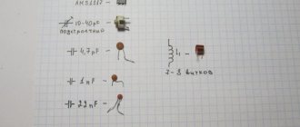
The procedure for manufacturing a 4G panel antenna according to Soviet drawings under the code F-20 is presented in the video below. The following materials will be required:
- rectangle of foil PCB 43 x 20 cm;
- 8 M3 bolts and 32 nuts for them;
- transparent printing film for inkjet printers;
- photoresist film;
- reagents - soda ash and ferric chloride.
The antenna vibrator pattern is printed on printer film. The textolite is cleaned and degreased. A photoresist film is glued to it using a roller, onto which the template is applied. The photoresist is illuminated with an ultraviolet lamp for 5 seconds (the time is indicated in the manufacturer's instructions for the film).
The exposed areas are frozen, and the areas of the film where the light does not reach according to the shape of the template are washed. The surface is heated with a hairdryer and immersed in a solution of soda ash, in which, after 2-3 minutes, the unexposed photoresist is washed off with a brush. The board is then etched with a ferric chloride solution for 35 minutes and again immersed in an alkaline solution for 1.5 hours in order to wash off the unexposed photoresist film. After this, the vibrator is ready; it is washed with warm water.
In each of the 8 segments of the vibrator, holes with a diameter of 3 mm are drilled in the center. A reflector of the same size as the panel (43x20 cm) is cut out of a tin sheet. The sheet is combined with textolite. Using a drill with a diameter of 3 mm, holes are made in the same places as the vibrator. M3 bolts are inserted into the holes of the textolite board; on the other side of the panel, 2 nuts are screwed onto each bolt. Two nuts and the thickness of the textolite give the desired 6 mm between the vibrator and the reflector. The tin sheet is tightened with nuts.
A cable is soldered to the resulting antenna and connected to the Wi-Fi router via a USB port. The central core is attached to the vibrator, and the braid is attached to the reflector. The router board is connected using hot glue to the back of the reflector. The vibrator is coated with a special non-conductive varnish to prevent copper oxidation.
Step-by-step instructions for assembling a simple external 4G amplifier with your own hands
Based on the fact that a factory repeater is not cheap, many decide to make it themselves. To make a simple device, the user will need the following materials:
- plastic;
- copper wire: 38-40 cm;
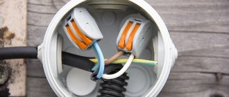
- connection block;
- coaxial cable: 8-10 m;
- fastening hardware;
- polymer pipe: 20 cm.
Required tool:
- pliers;
- soldering iron;
- insulating tape.
Work order:
- The wire is bent 90° in the middle.
- Next, the “whiskers” are folded on both sides at a distance of 9 cm from the center at 90°: you should get a rhombus (gravitating towards the volume of the square).
- The ends (2-2.5 cm) must be bent inward.
- A connecting block is connected to them.
- One side of the polymer pipe is cut lengthwise, and a hole is made on the opposite side.
- The pipe is attached to the connecting block.
- Next, the cable is connected.
- On one side, the outer insulation is removed.
- Conductors (external and internal) are connected to the contacts of the connecting block.
- Then the device is installed on a pole or on the roof of the house (dacha). It must be directed towards the nearest mobile operator station.
- The second end of the cable must be connected to the plastic plate.
- Testing is carried out: the turned on mobile phone is brought to the amplifier - the cellular signal strength indicator should increase by 1-3 divisions.
Communication range
The following factors influence the radio range:
- Location of BS and MS and terrain.
- MS power and sensitivity.
- Power and sensitivity BS.
- Antennas used on MS and BS.
- The will of the Lord God (experienced signalmen joke that this is the main thing).
Typically base stations have a power of 20 - 30 W. Antennas are used either whip or directional. The sensitivity of base stations is -100 dB - 115 dB. The user, of course, cannot change or influence all these parameters. The output power of the phone is 0.3 - 2 W, sensitivity - 90 - 105 dB. The sensitivity of a phone is mainly determined by the technologies used to create low noise input devices. If in areas of reliable reception the difference in sensitivity and power between models is almost unnoticeable, then in an area of uncertain reception it can become critical. Often the handset shows the signal level from the base station as 1 - 2 cubes (on the scale), but cannot establish a connection: there is not enough power. And although the ETSI standard regulates the standard output powers for each class of phone, the actual value may vary slightly. Tubes from SAGEM, Alcatel, and Motorola have good sensitivity. And all old phones pass in terms of power, especially Motorola. All phase 2 phones have approximately the same power.
As for the terrain, waves travel better on flat terrain and along the river. The higher you are (within reason), the better the signal. The forest sometimes dampens the waves more than urban buildings.
DIY Kharchenko antenna for 4g modem
The device is named after the engineer who first came up with it. This powerful external antenna for a 4g usb modem is made by hand; the diagram for the desired option can be found on the Internet. We will give the simplest one.
You will need copper wire and a 2mm thick aluminum sheet. First you need to bend the wire so that its sides do not touch in the middle. And solder the ends.
A hole for the cable is drilled in the center of the plate.
Then the wire is attached to the platinum. It should not touch the reflector.
Distance 3.6 cm.
Next, it is attached to the satellite dish bracket or simply to a stick.
If the modem has a connector for an amplifier, then all that remains is to connect it. If not, then you also need to prepare it yourself. Need copper foil for printed circuit boards. Wrap the modem 2/3 of the way around. Solder the cable. Make a second layer. And secure it.
All is ready!
You can also read the review of 4g Mimo antennas and find out how to set up 4g on your phone.
What is needed to create an antenna for the mobile Internet: materials and tools
DIY Wi-Fi gun: diagrams and drawings
A do-it-yourself antenna for a 4G modem should be created based on materials available in the house. It is better that they are already prepared. It all depends on what kind of receiver you plan to make.
Note! For some, any bare conductor will do, but the base (traverse) is best made of wood or polypropylene pipe. It must be durable.
In general, you will need:
- copper and antenna cables;
- soldering iron, solder and rosin;
- cable strippers;
- marker, chalk or regular felt-tip pen;
- centimeter or ruler (the first option is preferable).
By and large, this should be enough to build a simple receiver. The most important thing is the desire and collection scheme. Options for the latter are described below.
Antenna for the Internet at the dacha
The most common Internet option in rural areas is mobile. To increase the signal level and distinguish it from interference, owners of summer cottages use various types of antennas that allow them to establish uninterrupted radio communications. 3G and 4G coverage areas are available almost everywhere, but there may be problems with stable radio communication due to obstacles that degrade the signal.
The operating principle of all radio signal amplifiers is the same, but the design and technical characteristics differ from each other. Externally and in their use, they do not differ from ordinary television ones, they are only divided according to the power of receiving radio waves. The main characteristic of the antenna is the operating frequency. You need to find out which signal is the strongest in a particular place in order to determine the range of the radio antenna for the Internet in the country. A weak 4G signal can be preferred to a stable 3G.
Note! An external antenna for a computer for the Internet must be mechanically strong, resist wind, and be resistant to high humidity and temperature changes. To strengthen a weak signal, use a radio antenna that is pointed at the nearest base station
The higher it is raised above the ground, the faster the signal will be received. It is securely fixed in a position where signal reception is best, and it is easily accessible so that it can be corrected
To strengthen a weak signal, use a radio antenna that is pointed at the nearest base station. The higher it is raised above the ground, the faster the signal will be received. It is securely fixed in a position where signal reception is best, and it is easily accessible so that it can be corrected.
Moving the signal amplifier outside the building eliminates attenuation and reflections that are created by various parts of the house:
- a powerful 3G/4G signal from a cellular operator’s base station is picked up by a radio antenna, which is located on the facade or roof of the house;
- the signal is transmitted via cable to the modem, which is inserted into the router;
- The router distributes the Internet via a LAN cable, Wi-Fi to the N number of subscribers.
What is the Kharchenko antenna and how does it work
The so-called Kharchenko antenna, which is intended for a 3G modem, is a homemade model. There is nothing particularly complicated about its design. The zigzag design was proposed by scientist K. Kharchenko back in the 1960s. Today it is quite popular among radio amateurs not only due to its simple design, but also excellent repeatability and broadband. This last advantage applies particularly well to the spiral design.
In terms of their design, models can differ quite significantly. Based on the size of the plate, the frequency of the structure changes significantly. At the same time, you need to take into account that homemade antennas may include objects made of plastic and metal.
The antenna for the modem comes in different types. The simplest one is omnidirectional. It can receive and transmit signals in all directions equally intensively. In particular, this could be a simple quarter-wave vibrator. To put it simply, this is a piece of wire that has a length of a quarter of the wave of the signal that is being received.
A sector antenna can limit radiation in a specific sector. In particular, if you place an iron sheet behind the omnidirectional device, you get a sector design. Its sector will be 180 degrees. Such an iron sheet is called a screen.
The most effective is a directional design. Thanks to the correct choice of screen curvature, you can create a narrow beam that will emit a radio wave.
The main antenna units are:
- a vibrator that induces, induces, a wave of electromagnetic oscillations that are sent by the cellular operator’s transmitter;
- a cable together with a matching unit that transmits the induced signal directly from the vibrator;
- signal transmission unit from the cable directly to the modem input;
- a reflector that eliminates interference as well as reflected signals to increase receiving power.
The DIY Kharchenko antenna is an excellent device for anyone who wants to have high-quality communications without having to spend large sums of money. It is very easy to make even for an ordinary person who does not have the appropriate professional skills. The result is truly excellent. This design will last for a long time.
Design and dimensions of the Kharchenko antenna
A signal amplifier made using Kharchenko’s method is an excellent way to save on communication quality costs. This broadband zigzag antenna is famous among radio amateurs for its simplicity and durability; its manufacture does not require special knowledge and skills. The frequency of the amplifier depends on the size of the plate; some antennas are capable of supporting several bands at once.
To manufacture a receiving unit using Kharchenko technology, it will be useful to familiarize yourself with the main categories of Wifi antennas:
- Omnidirectional - receives and transmits transmissions in all directions with equal intensity. This is the simplest option, which is a quarter-wave vibrator and preferably a television coaxial cable. The capabilities of such an antenna correspond to ¼ of the wavelength of the received signal.
The simplest omnidirectional antenna
- Sector - limits the reception or transmission of a signal to one direction with partial capture of the sides. To make it, it is enough to place a curved sheet of iron called a screen behind the omnidirectional amplifier. Antennas with sectors of 120°, 90° and 60° are common.
- The directional type of antenna is considered the most effective option. With the correct curvature of the iron sheet, the radio wave forms a concentrated beam.
The main components of the signal amplifying antenna are:
- vibrator for electromagnetic waves that are induced onto it within the coverage of the telecom operator;
- an antenna wire with a matching component that transmits the signal transmitted by the vibrator;
- an element through which the cable signal is transmitted to the modem input;
- a reflector or screen to increase the strength and continuity of a received broadcast, which also blocks transmission interference and reflections.
Antenna Kharchenko
Antenna vibrator
Particular attention should be paid to the material from which the antenna is constructed and its dimensions. Signal amplifiers are primarily made from copper and, in some cases, aluminum. Waves of different frequency ranges differ in length, which determines the size of the vibrator. For example, for the 4G standard this parameter is about 115 mm. To calculate the wavelength of a certain range, it is necessary to divide the speed of their movement in megameters (300) by its frequency. Minor errors are allowed. The side length of one side of two equal rhombuses or squares is calculated by dividing the wavelength by 4. Approximate diagram of the Kharchenko antenna:
Biquad calculation scheme
In such projects, the following dimensions are usually used (indicated with values for a 4G amplifier):
- H—horizontal screen length (115 mm);
- B - vertical length of the screen (115 mm);
- D — distance between the screen and the vibrator (13.2 mm);
- λ—wavelength (115 mm);
- ρ — characteristic impedance (50 Ohm);
- f - range (2600 MHz);
- L1 - outer side of the square (28.9 mm);
- L2 - inner side of the square (27.6 mm);
- L3 - total length of frames (81 mm);
- L4 - frame width (40.5 mm);
- L5 - central opening between frames (1.7 mm).
The recommended width and height of the Kharchenko antenna reflector are individually equal to the wavelength. To build a 3G-4G amplifier vibrator, 25-30 cm of copper wire is enough. Its exact length, taking into account the folds in the example described, will be 237.9 mm. In the case of a homemade antenna, all given values can be rounded to whole numbers and small errors can be allowed.
Antenna cable
Coaxial cable markings
The use of wires with low characteristic impedance prevents power loss. Its ideal value for Kharchenko antennas, panel and many other 4G amplifiers is 50-75 Ohms. This will eliminate errors when receiving a Wifi signal; an exact relationship with the mechanical dimensions of the vibrator can also improve the effect of the device. It is not recommended to make a long wire from the vibrator to the modem, as well as to allow splicing or reconnecting it on the way to the receiving device. This can significantly reduce the quality of the connection.
An acceptable distance between the screen and the vibrator usually ranges from 0.1λ to 0.25λ. For coaxial cables with a resistance of 50 or 75 ohms, the recommended distance is 16.4 and 17.4 mm, respectively.
The best option would be a cable with a diameter of 2-2.5 mm, the cross-sectional thickness of which is at least 5 mm2. A product with a diameter of 2.3 mm and a section thickness of 4 mm2 is also suitable, but it will slightly reduce signal reception. The smallest permissible cross-sectional thickness of such a cable is 2-2.5 mm2. It can have a noticeable effect on the quality and attenuation of the signal, although in certain conditions it will also be a suitable indicator. The better the central opening of the vibrator matches the cable, the better amplification the device will provide. Good data transmission also requires symmetry of the squares of the antenna design and uniform dimensions of the shielding surfaces.
Reflector design
Antenna with reflector
To make an anti-interference screen, you will need a plate of any metal. Equally suitable are a piece of an unnecessary aluminum pan cut with a grinder, a panel of foil PCB, a tin plane cut with scissors, a non-working or extra CD/DVD disc (due to the presence of aluminum foil on one of its sides) and even cardboard or plywood covered with foil. Reflectors are also made in the form of a mesh or strips of wire.
Mesh reflector
Application of panel antennas for operation in 4G networks
An outdoor LTE panel antenna is most often used to improve the quality of data exchange in areas with poor reception.
Small dimensions and high technology make it possible to place a large number of elements in one housing, which is especially important when using MIMO technology
MIMO technology
MIMO technology allows you to increase the throughput of a data transmission channel to the maximum theoretically permissible value. This technique produces spatial encoding of the signal due to the fact that reception and transmission are carried out by different antennas. The main requirement for successful use of MIMO technology is that the coupling between antennas should be as weak as possible. Technical language says that the antennas should be weakly correlated.
MIMO antenna
Equipment that supports MIMO divides the signal into several streams, distributing them among users. If there are fewer users than the number of transceiver modules, then each client can receive a signal through several streams.
So the following happens:
- Data transfer speed increases;
- Noise immunity is increasing;
- Traffic interception becomes more difficult.
MIMO technology requires both provider and customer equipment to support it.
Simple external 4g antenna with your own hands
When thinking about how to make an antenna yourself, you need to evaluate what raw materials are available in the house. If a consumer of Internet services has a case from a computer that has fallen into disrepair at home or in the country, you can use it as the basis for an antenna. You will need to purchase a USB cord for a signal amplifier and scissors for cutting iron from the store.
You will need to cut out a structure from the back wall of the case, which is based on a rectangle 24 (width) by 20 cm, from which a thin long part 7 (width) by 14 cm extends down. In this “leg” a square hole is made for the cable (2 by 2 cm), as well as holes for a thin metal bending structure (the dimensions of the latter are 23 cm long by 2 wide), cut from the same body, and for a locking bolt. The scheme for cutting the body into components is very simple; the corresponding marks can be made with a pencil.
Description of a homemade receiver
With appropriate settings, this antenna is both an amplifier and a receiver. The inventor and scientist Kharchenko suggested using this biquadrat as an antenna. Biquadrat is a subspecies of loop antennas, which are primarily classified as zigzag.
K. P. Kharchenko proposed this device as an antenna in the middle of the last century (1961) for use as a television receiver. There is a good reason for this: it is a historical, recorded fact that, having tuned his antenna to a frequency of 14 megahertz and giving it the required position, the scientist received a signal from America.
Among the factory models of amplifier antennas, it is easy to find powerful devices with high performance. But quite often you can get by with a simple design that can be easily assembled from available materials with your own hands. It is enough to use the well-known development of Kharchenko.
According to the creator’s research, in terms of output parameters, the antenna reliably enhances the operation of digital devices operating on mobile platforms, generating an increase in signal reception of up to 3-4 dB, even without the use of a reflector, and with its implementation - up to 8-9.
Reasons for poor internet on your phone
If a user on his phone encounters problems with Internet speed, then this may be a consequence of certain factors. Some of them depend on the location.
If the connection speed is weak, then the reasons for this may be the following:
- Exceeding the permissible mobile traffic limit, as a result of which the speed will be reduced until the end of the day or month by the operator, depending on the tariff.
- Weak cellular network signal, as a result of which it does not pick up the 4G/3G network. Currently, the 3G coverage of mobile operators is quite good, in contrast to the 4G standard, which is still being introduced.
- Uneven terrain in which the subscriber is located. Hills, mountains, ravines and forests, as well as all kinds of concrete obstacles, greatly reduce the quality of the transmitted signal.
- Any operational errors, viruses or glitches.
- Long range to the tower.
Important! An Internet antenna for your phone can help strengthen a poor signal if it is caused by long distances and uneven terrain.
What does the signal level depend on?
Before you boost the signal of a 3G or 4G modem with your own hands, it is important to understand the factors that influence this parameter. Let's highlight the main points:
- High load on the base station. For best reception, try connecting to the Internet at night or early in the morning.
- Network coverage. Each provider has strong and weak signal zones. In the latter case, you will have to buy a more powerful receiver or look for other methods, the best way to catch the modem. The average range of the towers is limited to 30 kilometers, but the best reception is achieved at a distance of up to five kilometers.
- Receive the reflected signal. One of the main reasons for signal degradation is the reception of a “mirror” wave. Before arriving at the consumer, multiple reflections occur, which lead to a lot of additional interference. In such a situation, the Internet speed decreases, and the user ponders the question of how to strengthen and improve the reception of the 3G modem to increase the speed. In such cases, it may be necessary to install antennas or an extension cable.
- Presence of obstacles. In the city, there are many obstacles in the way of the signal: electromagnetic radiation, solid walls, partitions and much more. The more such obstacles, the lower the quality of the service received. Natural elements of the landscape, such as mountains, have no less influence.
Other hardware or software problems cannot be resolved. So, when considering how to increase the signal of a 3G modem, you cannot exclude the use of additional software to check the quality of the connection and identify the reasons for the slow speed. For example, the quality of the service may be affected by one or more programs. To fix this, you can remove unnecessary software from startup, disable automatic updates, and download torrent files.
Protection
To protect from external influences, the remote antenna must be placed in a housing of suitable dimensions. The exit points of the cable and fasteners must be carefully sealed.
Important! The body of the structure must be made of non-conductive material. It can be polystyrene or polyethylene
The first material is preferable because it allows the body to be assembled by gluing and is sufficiently resistant to ultraviolet rays, low and high temperatures.
External devices are at their greatest risk during a thunderstorm. A lightning strike that hits an antenna can instantly damage the internal circuits of all equipment connected to it. Therefore, if there is a possibility of a thunderstorm, you should disconnect the antenna cable from the modem or router connector.
Homemade devices for increasing the received signal power can improve the quality of reception, the speed of reception and data transmission, eliminating additional costs for more advanced equipment.
Assembly of the structure
Next, we connect the antenna cable to the homemade 4G gun.
Please note: the central core of the cable must be soldered to the second disk. While the cable winding itself is attached to the first disk.
A bracket (from construction steel angle) is screwed to the stud so that the antenna can be attached to the facade of the house.
A homemade 4G gun must be installed in such a way that it is directed towards the nearest repeaters.
Characteristics of external amplifiers for the modem
The main parameters characterizing the operation of an external antenna should be considered susceptibility, which determines the quality of the captured signal, and gain, which describes the signal redirected by the device. Both of these quantities are supposed to be measured in dBi.
Important! The characteristic that describes how sensitive an antenna is is a negative value (as opposed to gain). What unites these quantities is that the large value of the modulus of the number is highly valued
For example, a sensitivity of -85 dBi would be preferable to -70. In turn, a coefficient of 10 dBi is valued higher than 5.
Settings
The setup method is similar to how a satellite dish is installed on a television satellite. On the Internet it's a little different. The plate must be directed lower. You may even have to point it down. This is due to the curvature of the reflection. To set up a satellite dish as efficiently as possible, you need to rotate it and use a special program to monitor how the Internet connection changes. Once you are sure that you have obtained the maximum value, the antenna must be fixed.
The external 4G antenna is fixed, now we can move on to the next step. Now it's worth experimenting with focus. For different modem models it is necessary to configure the converter holder differently. To do this, you need to change the focus position and monitor the quality of signal reception.
In order to correctly adjust the focus, you need to know that the modem antenna is on the opposite side from the USB. Of course, this is not the case on all models, so it’s worth disassembling it to understand where the receiver is.
If you have not achieved line of sight conditions, then you should raise the structure. Increasing the diameter of the mirror can also help improve signal quality. A 4G directional antenna is capable of picking up signals over a long distance. How is diameter related to reception quality? On average, a dish with a diameter of 1 m provides a fairly good Internet connection at a distance of 30 km from the station. To connect the modem to your computer, you need to buy a USB cable. What should it be like? Of course, you should use a high-quality cord, a small cross-section with shielding and ferite at the ends. You can also purchase several of these cords and connect them together, without losing quality.
It should be remembered that you will not be able to use a satellite dish for television and strengthen your Internet connection. Of course, you can attach the modem to a satellite dish to boost the signal a little. But it should be remembered that if the dish is tuned to TV, you do not need to turn it away from the satellite. A high-quality signal can be obtained if the satellite dish is configured for line-of-sight conditions.
Wire antenna
Another primitive way to boost a dying mobile network signal is to use copper wire. It should cover the bottom of the modem where the internal antenna is located. About 20 - 30 cm of thread should remain free. We fold this free piece - it should be perpendicular to the modem, that is, vertically. We place the modem with a homemade antenna on the window and connect it to the PC using an extension cord.
Make a few turns around the modem and straighten the cable vertically
An extension cable can be purchased directly with the amplifier - this will also help improve performance.
Types of external antennas by design
In this case, there are several possible options:
- Parabolic;
- Pin;
- Sector antennas for 4G Internet;
- Circular omnidirectional;
- With wave channel;
- Panel.
Note! Each external antenna for a 4G modem has its own characteristics
Directional antennas (“Wave Channel”)
A characteristic feature of such products is a narrow radiation pattern. The main purpose is to receive and transmit signals while maintaining one direction. Depending on the installation, the effectiveness of two important parameters is determined:
- Radiation;
- Reception of radio waves.
This type requires additional adjustment of special precision
It is important to ensure that you point to the desired station. Only in this case will the device be as effective as possible.
This is how any antennas work to boost 4G, LTE, 3G signals.
Note! Often such structures are also called beam structures. Other names:
Other names:
- Yagi-Uda;
- Christmas tree;
- Wave channel. Another name is the MIMO antenna for a 4G modem with amplification.
Panel antennas
Such devices are among the most common for receiving and transmitting radio signals. A variety of directional models. But the radiation pattern of the panel ones is larger when compared with the previous type. Thanks to this, the process of setting up basic parameters is simplified. It is enough to correctly turn the device towards the base stations to get the optimal result from using the antenna to boost the 4G signal.
The products have three important advantages:
- Broadband;
- Versatility;
- Supports all popular signal transmission formats.
The kit consists of an antenna array, which itself is essentially dipoles located one below the other in two columns. Horizontal spacing is the name given to the method of arranging parts of the structure in this case. In the direction to the base station, the signal quality is constantly improving with this organization. Dipoles can be positioned differently, depending on the polarization:
- X-shaped in both columns;
- Horizontally, with an inclination of 45 degrees;
- Vertical.
Note! The 4G amplifier antenna frames are often combined into a single housing that looks like a flat panel. For this installation, the design received the name
Circular omnidirectional antennas
Suitable for use in conjunction with all current standards for data transmission and voice messages. Any modern technologies are supported:
- LTE 2600;
- UMTS-2100;
- LTE 1800;
- GSM-1800;
- GSM-900.
In this case, you can refuse precise installation in the direction of one or another base station. This is the omnidirectional variety. But their gain remains quite low. Only in some cases will it allow you to increase the signal level from uncertain to stable for a 4G LTE antenna for a USB modem.
Whip antennas
A variety of circular omnidirectional products. An asymmetrical vibration system is the basis for these devices. It is made as a rigid rod made of metal. The round shape has become a distinctive feature for the radiation and reception patterns. When organizing communications between mobile objects, this design option is very convenient. The signal comes from all directions, no fine tuning is required.
Sector antennas
Note! They are used when a base station is deployed, which is characterized by a large subscriber base. Products are designed specifically for operator towers using sector organization
The basis is a phased array circuit, with the formation of a 60-degree sector.
One of the main features of the design remains DC closure. Therefore, sector options are allowed to be used even where particularly difficult climatic conditions exist. The need for additional means for water protection then disappears. Directional 4G antennas cannot boast of such advantages.
Parabolic antennas
A relevant option if the operator’s tower is located far enough - at a distance of up to 20 kilometers or more. The solution has not become widespread due to difficulties encountered with installation and settings.
Note! Powerful parabolic 4G antennas are offset and direct-focus in design
MIMO antenna
What is the easiest way to make an antenna? Let's consider equipment for receiving a 4G signal LTE 800, which is based on the Kharchenko antenna - an in-phase array of diamonds. This design was invented by K.P. Kharchenko back in the sixties of last year. The main advantage of this equipment is that it is easy to assemble the antenna, and all parameters can be calculated using numerous online calculators on the network. Due to the unusual circuitry, the device rarely needs to be configured. If you need to make equipment to improve the 3g signal with your own hands, you can use one Kharchenko antenna.
Antenna Kharchenko
DIY 4G antenna for modem
MIMO technology uses an even number of antennas, we will have 2 DIY MIMO antennas: Downlink - from the satellite to the receiving device, and for sending - Uplink. If you look at the average indicators, you can use 2 antennas at 802 and 843 MHz, the connection will be made with a 50-ohm coaxial cable.
For 802 MHz the length in millimeters is:
- L1 – 93.5,
- L2 – 90,
- L3 – 250,
- L4 – 136.5,
- L5 – 4.8,
- H – 373,
- B – 373,
- D 45.5.
For 843 MHz the length in millimeters is:
- L1 – 90,
- L2 – 96,
- L3 – 238,
- L4 – 129.5,
- L5 – 4.6,
- H – 373,
- B – 355,
- D 43.
Important! The number of streams is equal to or less than the minimum number of antennas at the reception or output. When using MIMO 4×4, you can work in the range from 1 to 4 streams, but if we are talking about MIMO 4×2, then there can be only 1 or 2 streams.
LTE frequencies in Russia
To work you will need:
- a lattice or a piece of plywood covered with foil or foil tape, or galvanized steel (we use the latter option):
- wire with a cross section of 4 mm2;
- cable;
- wooden board at least 1.90 m long;
- polypropylene pipes;
- nylon clamps;
- a can of auto enamel;
- F-connector – 2 pieces;
- pigtail cable F-CRC9 – 2 pieces;
- Poxipol glue;
- drill;
- pliers;
- tape measure and ruler.
Sequencing:
- We make the frame in the shape of the letter P. To do this, we cut the board into three parts. The longest board (the top part of the letter) should be 1 m 20 cm, and the sides should be 35 cm each. You can cut all parts of the frame from different boards;
- We cut out 2 pieces from a sheet of galvanized steel measuring 375x375 cm. We fix the bases with dowels on the frame strictly at an angle of 45 degrees;
- In the center of each base we drill holes for the cable that will go to the modem. The diameter of the holes is 7 mm. We make markings for attaching the antenna;
- We cut the polypropylene pipe into several parts: 3 parts - 44.5 mm and 3 - 42 mm. These dimensions are directly related to the center of the wire;
General view of the device
Note! For stable and high-quality reception, it is important that spatial multiplexing technology is supported at the transmitting station, and that the antenna is used for the 4G modem.
- Let's start by assembling the 802 MHz antenna;
- According to the drawing, we place the pipes on pieces of galvanized sheets and glue them with Poxypol. Polypropylene tubes and glue are dielectrics, so when the antenna and these parts come into contact, the signal will not be distorted;
- Now we make the antenna itself from wire according to the dimensions indicated in the drawing. We make bends using pliers. In the obtained parameters, you need to subtract 4 mm, of which 1 mm goes to the error in the center, and 3 mm when bending with pliers;
- Next, we strip the cable and the central core, solder it to the ends of the wire, and solder the braid to the bend;
- We pull the cable through the polypropylene pipe into the hole that we drilled in advance;
- Now we check all the dimensions and, if necessary, align the antenna;
- We fix the corners of the diamonds on polypropylene holders using Poxypol. In order for the wire to be secured, some kind of weight should be placed on top;
Assembling a homemade antenna for 4G reception
- We measure the distance between the ends of the antenna and the bend of the wire in the middle of the structure; it should be 4.8-5 mm. 4.5 mm is the gap between the wire and the bend; it is difficult to adjust, but this can be done with nail scissors, placing them in the middle. Now we attach the middle of the antenna with glue;
- The sequence for assembling a DIY MIMO antenna at 843 MHz is exactly the same. It is important to note that the antennas must be located at an angle of 90 degrees to each other. X-polarization has a greater effect than vertical polarization. Arranging antennas in this way creates a level playing field for them;
- To prevent the cables from running through the holes, we tighten them from the back with nylon clamps and glue them;
- Now we carry out control measurements according to the diagram and, if necessary, make adjustments;
- To avoid oxidation, we coat the wire and galvanized sheets on top with enamel;
- We connect the cables through F-connectors to the pigtail and only then to the modem;
- We are testing the system. The creation of the MIMO 4G antenna with your own hands is completed.
In order to debug the operation of the device, the structure should be positioned correctly. General rules say that it is better to take the antenna outside and raise it as high as possible. In addition, the antenna must be directed strictly towards the dispensing station. However, these tips do not always work. The higher the MIMO antenna is raised, the more cable you will need to lay before connecting the modem yourself, but in this case, part of the signal will be canceled out by interference caused by this very cable. Outdoor installation is not always favorable for the device. If oxidation can be eliminated by painting, then one cannot ignore that the geometry of the structure can be disrupted by gusts of wind. In addition, in the direction towards the station there may be various obstacles that will dampen the signal.
To debug the antenna, sometimes you have to try several installation options, but then this equipment will work in 3G 4G LTE.
Other homemade antenna options
Ideas for homemade antennas could be the following:
- Colander 4G. Everyone has a simple aluminum colander in their home. You need to fix the USB extension cord on the handle of the cookware. Connect a modem to it - it should ultimately be within the circle of the bowl. We direct the colander to the base station and catch the signal.
- 3G/4G satellite dish. If you have an old satellite dish, use it. The signal will be amplified significantly, since the antenna will be outdoor. Remove the converter from the boom. Secure the modem at this location. Naturally, you will need a USB extension cable - carefully stretch it to the modem and connect it. Now point the dish at the operator tower. To adjust, you will need to rotate the plate slowly to achieve maximum effect.
- Antenna "Double Ring". The method is similar to the Kharchenko antenna. It is just as effective, but here you also have to work hard to make the antenna.
Production of biquadrat Kharchenko
In photographs of homemade antennas for 3G modems you can see its approximate appearance. First, you need to make markings on the copper wire with a pencil: the length of the outer side of each square should be approximately 35-36 mm.
Carefully bend the wire along the markings, helping yourself with pliers. You should get a symmetrical design of two squares touching at the corners. Remove the remaining pieces of wire.
Make a hole in the cover and insert the end of the cable into it. Separate the cable, exposing the inner conductor and shield for soldering.
Next, you should solder the antenna to the cable and connect it to the modem. Soldering proceeds as follows: solder the central core to the middle of the antenna on one side, and the screen on the other. Then move the cover towards the antenna; you can further strengthen and insulate the structure with glue or sealant.
Insert the reflector disk into the wire through the hole, move it towards the antenna and glue it to the cover. Solder the connector to the cable on the other side for connecting to the modem. Connect the antenna to the modem. Enjoy the result of your work!
Technical data and characteristics
Depending on the range, radio antennas have different designs and dimensions. Designs of existing receiving and transmitting devices:
- "wave channel";
- pin;
- Kharchenko zigzag antenna;
- planar.
The directional “wave channel” has the highest gain among all known antennas. If the distance from the base station to the village is several tens of kilometers, then a parabolic antenna may be the only solution for mobile Internet.
The simplest type of pin is a vertical conductor mounted on an insulator and connected at one end to a receiver.
A panel antenna is a version of a radio antenna that catches a scattered signal. When there are any obstacles, this model is suitable for stable operation of reflected waves.
The universal model of the Kharchenko radio antenna, which can be made by hand, consists of two copper squares, 3.5-4 mm thick. Simple in design, the frame model creates an excellent reinforcing effect.
Depending on the connection method
SMA modification
Several conditions must be met for this modification of the antenna for a 4G router to work for the user:
- 3G/4G modems equipped with TS-9, CRC-9 connectors.
- Models with SMA connectors through which external connections are organized. The modem is already built into these routers. All you have to do is insert the SIM card.
- You will need not only the device itself, but also 2 cable assemblies with SMA connectors, up to 10 meters long. Then it’s easy to enhance the signal quality.
- To connect the cable, it is recommended to purchase two special adapters or pigtails.
Note! The use of this technology is relevant if there are connectors where external devices are connected. You can also use adapters to connect to regular USB modems
But a high-frequency cable in such situations will be too expensive. And losses in signal quality will remain serious. We'll have to strengthen
You can also use adapters to connect to regular USB modems. But a high-frequency cable in such situations will be too expensive. And losses in signal quality will remain serious. We'll have to strengthen it.
BOX modification
The purchase of such products requires the presence of the following equipment:
- USB extension cable.
- Modems for outdoor antennas for 4G modems, supplemented with TS-9, CRC-9 connectors.
Important. At the rear, the device is complemented by a sealed box of small dimensions
Adapters for connecting to a modem are usually already built into this part. A modem with 3G/4G technology is installed inside the box, to the connectors of which adapters are then connected. The next step is to insert a USB extension cable into the box. Usually a special sealed lead-in is used. All that remains is to connect to the modem.
A universal WiFi router with a USB connector and 4G support is needed if you plan to use the Internet on several devices simultaneously.
If the user already has a 3G/4g modem, the BOX modification will be an excellent way to save money. Only the modem limits support from certain telecom operators. The overall stability of operation via a USB extension cable largely depends on specific models.
USB modification
This is a kind of ready-made complex that allows you to amplify signals that are transmitted according to conventional standards. The user does not need any additional devices; a standard set is sufficient for amplification.
Note. A universal 4G modem is already built inside from the start
But 3G standards are also supported. It is enough to connect a SIM card from any operator operating in Russia. After this, the device is connected to the computer. Another option is to use a router together with a USB cable 10 meters or more long.
Signal loss on cables when using USB modifications is completely eliminated, the connection is stable.
Note! Only Ethernet modification devices will be a suitable solution if the connection requires a cable longer than 10 meters
Ethernet modification
Another type of ready-made kits that amplify the signal for modern 3G/4G standards. The kit comes with a built-in 4G modem, which is complemented by a router with a POE adapter. This designation is a technology that allows you to connect regular Ethernet cables. Their length, at the user’s request, can reach 100 meters.
When the connection freezes, the device supports automatic rebooting. Characterized by compatibility with WiFi routers of almost any modification. The rating will help you make your choice.
Note! Signal loss on cables is almost completely eliminated, which already distinguishes this option from the SMA 4G antenna
What types of 3G/4G antennas are there?
Antennas (both purchased and homemade) are divided into several types depending on several indicators. If we talk about the installation method, there are indoor or outdoor antennas. The latter are more effective because they work in open space, where there is less interference. They are suitable for those subscribers who live far from the tower.
Indoor antennas are not as effective as outdoor antennas
Based on the receiving signal, antennas are divided into broadband and narrowband. The first ones are more functional - they are capable of receiving 2G and 3G signals when, for example, 4G does not work.
Antennas are also divided into directional, omnidirectional and sectoral. The last two types are capable of catching signals from several towers at once. There are also conventional devices and MIMO antennas - advanced equipment with two antennas at once, which receive the signal separately from each other, but transmit the signal to the modem simultaneously. They can increase speed up to 100 Mbit/s.
The MIMO antenna essentially has two receivers, hence its effectiveness
Depending on the presence of an amplifier in the antenna, devices are divided into active and passive. Passive ones, where there is no amplifier, do not improve the mobile network signal as much as active ones, but they do not need to be connected to an outlet (the amplifier is powered by an electrical network).
In what cases is an antenna needed for a modem?
The antenna will improve the mobile Internet if there are two or even one division on the signal icon. The external antenna components will pick up the signal where the built-in antenna cannot. If there is no signal at all, there is a chance that even an external antenna will be powerless in your case.
Many modems have a connector on the side for connecting a cable from an external antenna
If the problem is only in speed - there are a lot of bars, most likely the reason is that the operator's base station is overloaded with requests from subscribers. Even if you install an antenna, the speed will not increase. In this case, it is recommended to change the operator or try to point the antenna at another company tower.
Device creation process
First you need to create a vibrator. Size and symmetry are of paramount importance. To give maximum symmetry to the installation, it is necessary to make all the edges of the squares absolutely identical. This can be achieved in two ways:
- Be sure to pre-mark the wire with a marker;
- apply a control template of a certain length.
In the first method, pliers are placed on the wire marking and the latter is bent at an angle of 90 degrees to control the bend along the square.
In the second case, it is necessary to separate a part of the wire on a scale slightly larger in size than the sides of the square, and then sharpen it with a file or coarse sandpaper to the control size. The completed template, together with the wire, is placed in the jaws of the pliers so that one end, simultaneously with the wire, rests against a solid plane, and the other converges with the output plane of the pliers. Also, to guarantee the evenness of the surfaces, you can make calculations online using the Kharchenko antenna calculator specially designed for such purposes.
After this, the vibrator is bent with manual effort, using a control template for each edge of the square. After the wire is completely bent, the remaining part is removed with side cutters. A verification measurement of the faces takes place, which ensures symmetry in the position of each side in the same plane.
Connection and signal transmission options
In the middle of the bottle cap, a hole is drilled with a drill or cut with a knife, slightly smaller than the diameter of the cable (to make the structure more stable). The end of the wire is inserted. After this, it is disassembled so that the central core with a place for tinning and soldering is exposed.
The wires are connected with any soldering iron (you can even use a homemade one). When soldering is completed, the cover is pulled onto the vibrator, moving along the cable.
The reliability of the connection can be increased by using glue and making small cuts in the plastic plug.
The DVD disc is inserted into the cable through the central hole and glued to the end of the plug. In this installation, the reflector and vibrator do not make electrical contact with each other.
The antenna vibrator assembled in this way, together with the reflector, guarantees good reception of the electromagnetic signal wave without contact from the transmitter and redirects it along the coaxial wire. Now all that remains is to redirect it to the modem.
Redirecting the 4G signal to the modem can be resolved in two ways:
- make a direct connection of the coaxial wire cables directly to the modem board;
- use the antenna made by Kharchenko as an intermediate amplification link and use it to transmit the received signal to the integrated antenna of the receiving device.
The first method, in turn, involves two solutions depending on whether the modem has a special connector for connecting to an external antenna or whether it is missing.
If there is a connector, this will save the amateur craftsman from solving additional problems. Then you only need to solder the ends of the coaxial wire to the second part of the connector and connect the antenna through it.
If there is no connector, then to organize a direct connection to the modem board you will need not only disassembling the coaxial cable, but also soldering the core conductor with the screen layer to the microcircuit tracks. This is a very complex and delicate technical work that must be performed accurately, safely and in full compliance with technology. Otherwise, the modem will fail, and then you will have to buy it again.
Send data wirelessly
Anyone can cope with this task. It will be necessary to solder electrodes to the output points of the coaxial wire - they will become a generator unit and will emit a generally accepted and intense magnetoelectric wave directly to the modem antenna. You need to make one turn with any thread along the outer contour of the modem body and measure its size with a ruler. After this, you need to add 5 mm and cut a couple of strips of 75 mm in length and 45 and 27 in width from foil or a tin can.
The wide part for the core core needs to be bent according to the configuration of the modem, and for the screen - in a semicircle, and then soldered to the Kharchenko antenna.
The electrodes need to be separated a short distance and directed in such a way that they produce and address the received magnetoelectric signal to the integrated antenna of the modem. Their best location can be found experimentally.
Now everything is ready. All that remains is to insert the 4G modem into the laptop connector, and then check the quality of the network.