What is a zero sequence?
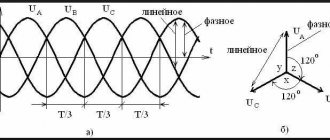
The vast majority of networks are powered by a three-phase system. Which is characterized by the fact that the voltage of each phase is shifted by 120º.
Rice. 1. Voltage form in a three-phase network
As you can see from Figure 1, diagram b) shows the operation of a balanced symmetrical system. Moreover, if you perform a geometric addition of the presented vectors, then at the zero point the result of the addition will be equal to zero. This means that in 110, 10 and 6 kV systems, which are characterized by grounding of the transformer neutrals, under normal operating conditions there will be no current in the neutral. It should also be noted that geometrically, phase changes can be divided into the following types:
- direct sequence, in which their alternation looks like A – B – C;
- reverse sequence, in which the alternation will be C – B – A;
- and a zero sequence variant corresponding to the absence of a shift angle.
For the first two options, the shift angle will be 120º.
Rice. 2. Direct, reverse and zero sequence
Look at Figure 2, here the zero sequence, unlike the other two, shows that the vectors have the same direction, but their displacement in space between themselves is 0º. A similar situation occurs with a single-phase short circuit, while the currents of the two remaining phases rush to the zero point. This situation can also be observed during phase-to-phase faults, when two of them, in addition to overlap, also reach the ground, and only one phase current will flow at zero.
If a three-phase short circuit occurs in the neutral of the windings, the current will not flow, despite the accident. Because zero sequence currents and voltages will still be absent. Despite the fact that phase voltages and currents in this situation can increase significantly in comparison with the nominal ones.
Operating principle of TZNP
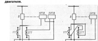
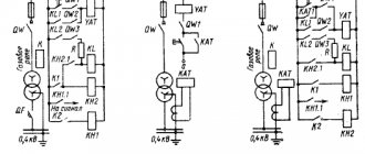
Almost all relay protections, the action of which is adjusted against the appearance of zero-sequence currents, have a similar principle. Consider the following diagram demonstrating the effect of protection.
Schematic diagram of the simplest TZNP
Here is an option for switching on a current relay T, which is connected to the secondary windings of current transformers (CTs) assembled in a star. In this situation, the neutral wire from the star of the transformer windings filters out the zero sequence components if they occur. Provided that the system operates symmetrically, the windings of relay T will be de-energized. And provided that a ground fault occurs in one of the phases, the CT will react to this, causing current to flow through the neutral wire. This will be the very component of the zero sequence, due to which the relay winding T will be excited.
After which a time delay occurs, determined by the parameters of relay B. When the set period of time expires, the current protection sends a signal to the corresponding switching installation U, which disconnects the three-phase network. More complex circuit options may also include a power relay, which allows you to debug the operation of the protection in direction.
In the case of phase-to-phase damage, the symmetry will not be broken, but only the magnitude of the currents will change. And the CTs will continue to compensate for the currents flowing into the neutral wire. The advantage of this scheme is that at maximum operating currents, the protection will still not operate, since symmetry will be maintained.
But if there is a significant difference in the magnetic parameters of the measuring transformers, an imbalance will occur in the system, and an unbalance current will flow through the neutral conductor. This can cause false trips of current protection even in those networks where the rated power supply is observed.
Rules for selecting current transformers.
In order to reduce the imbalance that affects the correct operation of the current protection, CTs are selected in which secondary currents will not create overflows. Why should they meet the following requirements:
- Have identical hysteresis curves;
- Equal load of secondary circuits;
- The error at the boundaries of network sections should not exceed 10%.
It is prohibited to connect any other load to their secondary circuits, leading to a distortion of the magnetization curve in at least one CT. Therefore, in practice, when operating currents arise from a symmetrical system, it is recommended to replace not one or two, but all three transformers at the same time.
Application area
Current protection, capable of responding to the appearance of a zero sequence, has found quite wide application in lines with a grounded neutral. Since short circuit currents in them reach the highest values. But with an isolated neutral, its installation is impractical, so TZNP are not used in them. Today, TZNP installations are widely used:
- on the buses of regional substations to protect power equipment;
- in switchgear of transformer, switching and complete substations;
- in current circuits of large industrial facilities with three-phase power equipment.
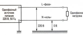
Where does the 380V outlet come from when the zero is broken - clearly, accessible, without formulas.
Surely each of you has had household appliances burn out due to overvoltage at least once in your life. At the same time, many have heard that this often happens due to a zero break.
Let's visually, without formulas, vector diagrams, zero point offsets, etc., from the point of view of the average person, try to figure out how the voltage of 380V, instead of the usual 220V, can end up in your sockets.
After all, a logical question really arises: how is it that one of the wires has broken or burned out, but the voltage does not disappear, but becomes even greater.
Understanding this process will be useful to every consumer, so that later there will be no questions about why electricians are trying to “stick” incomprehensible relays costing several thousand rubles into the electrical panel.
To clearly understand the essence of this phenomenon, let's remember the difference between the serial and parallel circuit for connecting electrical receivers.
With a parallel connection, the phase and neutral conductors simultaneously reach all consumers in the circuit. Let's draw a diagram where these consumers are ordinary incandescent light bulbs.
The input voltage is 220V. With this connection, the voltage on each light bulb will be the same, and with a sufficient cross-section of conductors and a low load, it will not differ much from the input one.
In this case, turning off or turning on each light bulb in turn will not greatly affect its values. It is according to this scheme that all sockets in your apartments are connected.
However, if the voltage is the same, the current in the circuit will be different. Its total value is the sum of the currents passing through bulb No. 1 and No. 2.
You can turn on more powerful devices (200W lamps, kettle), and everything will work perfectly.
The serial connection scheme already introduces significant changes. Here the supply conductor (this can be phase or zero) first comes to the first light bulb, and then leaves it to the next one.
Only after this does it return to the input machine or to the general network.
The number of pantographs does not matter, there can be 2,3,4 or more. The main thing is that they are strictly connected one after the other
What will change if you turn on two 100W lamps in series? What will happen is that the voltage on them will drop by about half.
In this case, the total input voltage will be the sum of the voltage drops across lamp No. 1 and lamp No. 2. That is, 110v on one and 110v on the other. By the way, this seemingly disadvantage can be used very cleverly in several ways.
Let me remind you that in a parallel circuit, U was the same everywhere, no matter at what point. Here the current will be the same, while in any part of the electrical circuit I=I1=I2
However, such a situation with a uniform voltage drop will only be observed if all electrical receivers are of the same power. Instead of one 100W lamp, just screw in a 200-watt one, and you will immediately see the difference.
A 100W bulb will have a voltage of 146V and will burn quite brightly. At the same time, a more powerful 200 watt one will barely glow.
This is due to the fact that the voltage drop directly depends on the consumer resistance. On more powerful devices the resistance is low.
Here are approximate data for standard light bulbs designed to operate on a 220V network:
{SOURCE}
Selecting settings for TZNP
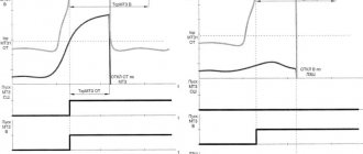
To ensure the stepwise principle of line output, the current protection that controls the appearance of a zero sequence in the circuits must correspond to the selectivity of operation. Here, selectivity refers to the sequential switching off of certain sections of the circuit, depending on their significance, in order to determine the location of the damage or highlight the damaged gap. To do this, select the appropriate time settings for protection. Consider an example of setting settings in this diagram.
Setting selection example
As you can see, in this case the TZNP is configured according to the same principle as the maximum current protection, but with a shorter time delay. In this example, each subsequent protection stage withstands a time delay for an interval Δt greater than the previous one. That is, the response time of the first current cutoff, in comparison with the second, will be calculated according to the formula: t1 = t2+ Δt. And the response time of the second in relation to the third will be t2 = t3+ Δt. Thus, each subsequent relay performs the function of backup protection.
If the windings of the converter devices are connected according to the star-delta system, as well as the star-star system, the TZNP of the primary and secondary circuits do not match. Due to the fact that a short circuit in high voltage lines will not necessarily cause the appearance of zero sequence components in the low windings and the circuit fed by them. Since the TZNP selectivity for each of them must be built independently, in practice their independent operation must be ensured.
This system of stepwise protection allows minimizing the further transfer of damage to other sections of the network and power equipment. It also helps to remove the personnel servicing these devices from danger. The main requirement for current protection is the prevention of false switching in relation to the corresponding trigger zone.
Practical implementation of TZNP
Today, current protection that responds to the occurrence of a zero sequence can be implemented by microprocessor units and through relays. In most cases, outdated relays are widely replaced with newer versions of current protection. But, in addition to TZNP, remote, differential protection and other devices are configured for operation. Whose work is based on both symmetrical components and other network parameters.
In addition, in its classic design, TZNP does not have the ability to determine the location of damage. That is, it does not matter to her where the break occurred. Therefore, directional protection is used to determine the direction in which current flows towards ground. Such a system is built not only on currents, but also on voltage arising from the zero sequence. These values are supplied from voltage transformers connected in an open delta system.
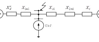
Directional protection operating diagram
When there is a short circuit in the current protection redundancy zone, voltage is supplied to one of the windings of the power relay, and a zero-sequence current used for current protection is supplied to the second winding. Provided that the power vector is directed into the line, the power relay unblocks the operation of the current protection. Otherwise, when the power direction indicates that the fault has occurred in another section, the power relay will continue to block the current protection from tripping.
Today, the practical implementation of such protection is carried out using REL650 microprocessor units or EPZ-1636 relays. Each of which already includes current cut-off, distance protection, and a starting relay to restore power.
Designation of neutral protective conductor
Color of the neutral protective and neutral working conductors
Most often, the marking of the neutral protective conductors is yellow-green. The PUE establishes the basic rules for choosing the cross-section of the current-carrying wire.
The PE has its own grounding loop, or its main tasks can be assigned and combined with the neutral wire, in this case it all depends on the installed grounding system in the building structure. The combination of two conductors is called PEN, its cross-sectional area must be no less than the cross-sectional parameters of the working wire N.