Purpose of conductors
The use of neutral conductors in an electrical panel
The neutral working conductor has another name - network conductor. The load current flows through it. In the diagram it is designated by the Latin letter “N”.
The main task of the neutral protective conductor is to ensure safety. In systems with a zero terminal of a solidly grounded transformer, it switches the conductive parts of electrical receivers and the zero point of the supply transformer. In emergency or emergency situations, they are under attack.
The following electrical elements are subject to protection from indirect contact (according to PUE 1.7.76):
- housings made of metal, portable and mobile devices;
System with PEN wire and two zeros - metal structures of transformers, electrical machines and lighting devices;
- metal cases of various designs with electrical equipment, cable couplings, trays and various distribution devices;
- steel casings of floor and apartment panels, distribution panels.
As protection, switching of these devices with a solidly grounded neutral in TN or TT, IT systems is used. The last two are grounded.
Schematically, the neutral protective conductor is designated “PE”. When the electrical circuit is operating normally, no current flows through the PE.
In the diagrams, the combination “PE” means the neutral protective conductor, as well as all protective segments of the circuit, for example, laid buses and conductors, grounding conductors, individual conductors in cables, as well as a wire in the potential equalization system.
The difference between neutral protective and working conductors
Before starting work, it is important to familiarize yourself with the features and characteristics of conductors and conduct a comparative analysis.
| Name | Description |
| N – neutral working wire | Together with the phase wire, it takes part in the continuous and unhindered supply of power to household appliances and other electrical appliances. A working current constantly flows through it. |
| PE – neutral protective conductor | Does not participate in the provision of electrical appliances and household appliances with electricity. The main task is protection against indirect interaction in networks with a solidly grounded neutral. |
Zero working conductor
The neutral working conductor is also called neutral.
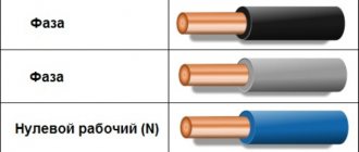
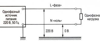
Most household appliances are powered by an alternating voltage network of 220 V. In order to supply this voltage to them, one phase wire is used, and the second is neutral. The phase has a potential of 220 V, and the neutral wire has a potential of 0 relative to the power source and the phase wire. Zero is designated as N, and its insulation should be blue or white-blue, in accordance with the color marking of the cable. Often the functions of the neutral working wire and the protective wire are combined (for TN-C grounding systems). This joint conductor is designated PEN and has yellow-green insulation with blue markers (tags) at the ends. Similar color designations are used in Europe. In the US, the neutral working wire may be designated white or gray.
Different power lines and networks can use different neutrals (insulated, solidly grounded, effectively grounded). The choice of one option or another is determined by the functional purpose of the network.
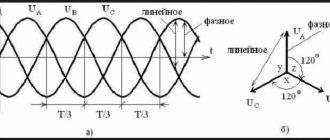
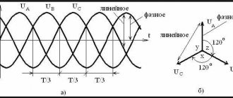
At the moment, almost all residential buildings in Russia have grounding systems with a solidly grounded neutral. In this case, electricity is supplied from three-phase generators in 3 phases with potential, and also a fourth wire comes from the generator - neutral (working zero). The three phases at the end of the line are connected in a star: this creates the end of the neutral, which is connected to the neutral of the supply generator. The wire connecting these two neutrals is called the working neutral conductor of the network.
In the case of a symmetrical load on all phases, there is no current in the working zero. If the load is distributed unevenly, then an unbalance current flows through the zero working conductor. Using such a circuit makes it possible to achieve self-regulation of all three phases, while the voltage across them is almost equal to each other.
To increase safety, the working zero is grounded at the end of the line, and additional grounding is often used: at the beginning of the line and at its different points. In houses, the neutral working wire is supplied to a switchgear, from which separate neutral conductors already go to direct consumers of electricity (for example, to apartments).
In addition to networks with a solidly grounded neutral, electrical networks with an isolated neutral are also used. In such networks there is no neutral working wire. Instead, if necessary, a neutral grounded wire can be used.
When using three-phase power lines in a building, the cross-section of the neutral working conductor must be no less than the cross-section of the phase conductors, with sizes of the latter up to 25 mm2 (aluminum). If the cross-section of the phase conductors is more than 25 mm2, then the cross-sectional area of the working zero must be at least 50% of their cross-section. If the network uses a grounding working zero, then when connecting the wire to the main grounding bus, the identification sign “ground” must be present.
Even if the protective and working zeros are connected at the switchgear, their further combination at consumers is not allowed. That is, further through the apartments two separate wires PE and N are run. They cannot be connected because when the phase is closed to the neutral working conductor, and all devices connected to the protective conductor PE (in the case of combining PE and N) will be under the phase conductor voltage, which creates a high probability of electric shock to a person.
Designation of neutral protective conductor
Color of the neutral protective and neutral working conductors
Most often, the marking of the neutral protective conductors is yellow-green. The PUE establishes the basic rules for choosing the cross-section of the current-carrying wire.
The PE has its own grounding loop, or its main tasks can be assigned and combined with the neutral wire, in this case it all depends on the installed grounding system in the building structure. The combination of two conductors is called PEN, its cross-sectional area must be no less than the cross-sectional parameters of the working wire N.
Neutral protective conductor: designation on diagrams and installation rules
How to divide the incoming PEN conductor into N and PE
Electrical receivers must be powered from a 380/220 V network with a TN-S or TN-CS grounding system. When reconstructing residential and public buildings with a network voltage of 220/127 V or 3 x 220 V, the network should be switched to a voltage of 380/220 V with a TN-S or TN-CS grounding system.
This translation allows you to connect protective contacts in all sockets, thus allowing you to ground all home appliances and protect a person from electric shock.
Today, almost everywhere in the private sector and in many Soviet-built houses, the old TN-C grounding system is used. Therefore, when reconstructing electrical wiring, you need to switch to TN-CS, i.e. you need to divide the PEN conductor into independent N and PE.
GOST R 50571.1-2009 will give us the answer to this. Clause 312.2.1 contains the following lines:
It is prohibited to use PEN conductors in electrical installations of residential and public buildings, retail establishments, and medical institutions. The PEN conductor of the distribution network must be divided into neutral and protective conductors at the input of the electrical installation
We all live in residential buildings and, according to this paragraph, we see that the PEN conductor is prohibited from being used in our country. This paragraph also says that separation must be performed at the input of the electrical installation. In private houses, cottages and dachas this must be done in the input metering panels, and in apartment buildings this must be done in the ASU.
After dividing the PEN conductor into N and PE in the input panel, it is no longer possible to combine them back, i.e. forbidden. This is stated in the PUE clause 1.7.131.
What kind of lighting do you prefer?
Built-in Chandelier
Also from this point we see that for separation you need to prepare two tires. One bus for connecting neutral working conductors and the second for connecting neutral protective conductors. These buses must also be connected to each other. This connection is made with a cable jumper.
The incoming PEN conductor must first be connected to the PE bus and then a jumper must be made from this bus to the N bus.
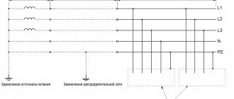
When using the TN system, it is recommended to re-ground the PE and PEN conductors at the entrance to the electrical installations of buildings, as well as in other accessible places. For re-grounding, natural grounding should be used first. The resistance of the re-grounding electrode is not standardized.
Also in this paragraph it is written that repeated grounding is not standardized, but it is still worth making the grounding loop reliable and of high quality. According to standards, the insulation resistance of the ground loop should not exceed 4 ohms. You yourself will not be able to measure this parameter without a special device.
This was a small theory on dividing the PEN conductor into N and PE with references to the clauses of the regulatory documents.
Now let's look at some visual diagrams that show this division. These diagrams will help you better understand how this is done.
Electrical installation grounding
- intentional electrical connection of its body with a grounding device.
Grounding of electrical installations is of two types: protective grounding and grounding, which have the same purpose - to protect a person from electric shock if he touches the body of an electrical device, which, due to an insulation failure, is energized.
Protective grounding is the intentional connection of parts of an electrical installation to the ground. They are used in networks with an isolated neutral, for example, in old houses with 220V networks.
There are two types of grounding conductors - natural and artificial.
Natural grounding conductors include metal structures of buildings that are reliably connected to the ground.
A distinction is made between a neutral working conductor and a neutral protective conductor.
The neutral working conductor is used to power electrical installations and has the same insulation as other wires and a sufficient cross-section for the operating current.
Preventive control of insulation is carried out at least once every 3 years. The insulation resistance of the wires is measured with megohmmeters for a rated voltage of 1000 V in areas with the fuse-links removed and the pantographs turned off between each phase wire and the neutral working wire and between every two wires. The insulation resistance must be at least 0.5 MΩ.
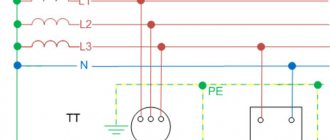
Grounding systems differ in connection schemes and the number of neutral working and protective conductors.
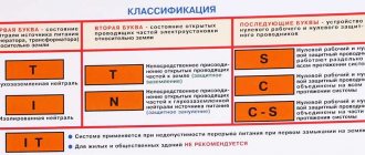
The first letter in the designation of the grounding system determines the nature of the grounding of the power source.
T - direct connection of the neutral of the power source to ground.
The second letter in the designation of the grounding system determines the nature of the grounding of the exposed conductive parts of the building's electrical installation.
T is the direct connection of the open conductive parts of the electrical installation of the building with the ground, regardless of the nature of the connection of the power source with the ground.
N - direct connection of open conductive parts of the building's electrical installation with the grounding point of the power source.
The letters following the dash N determine the method of constructing the neutral protective and neutral working conductors.
C - the functions of the neutral protective and neutral working conductors are provided by one common conductor PEN.
S - the functions of zero protective PE and zero working N conductors are provided by separate conductors.
The TN-C system includes three-phase four-wire (three phase conductors and a PEN conductor, combining the functions of the zero working and neutral protective conductors) and single-phase two-wire (phase and neutral working conductors) networks of old buildings.
Currently, the use of the TN-C system on newly constructed and reconstructed facilities is not allowed. When operating the TN-C system in an old building intended to house facilities, computer science and telecommunications, a transition from the TN-C system to the TN-S system (TN-CS) should be ensured.
Expert opinion
It-Technology, Electrical power and electronics specialist
Ask questions to the “Specialist for modernization of energy generation systems”
Pen conductor: what is it in electrical engineering, the division of pen after the meter into working and protective. What we used to call zero and ground in the PUE is called zero working conductor N and zero protective conductor PE. Ask, I'm in touch!
Laying rules
Before proceeding with installation, you need to familiarize yourself with the rules that apply to PE laying:
- There must be no devices in the line that could cause disconnection or disruption of the circuit integrity, for example, removable inserts, switches, circuit breakers and fuses.
- All equipment and live parts are connected directly to protective grounding.
- It is prohibited to connect several electrical devices using the loop principle.
- A separate terminal (clamp) is allocated on the PE distribution bus. It is prohibited to simultaneously connect the neutral protective and working wires to the same terminal.
- If the residual current circuit breaker equipment is installed in a distribution board, N and the protective conductor should not have contacts on the same line. If you neglect this rule, the RCD will have many false alarms.
- The cross-sectional area of working wires must be larger than the cross-section of the protective grounding.
- The neutral protective conductor must be laid near the working wires.
- For grounding, you cannot use objects and communications not intended for this purpose. Most often, in this case, fittings in the walls, pipelines and heating radiators are used for other purposes.
- It is prohibited to connect PE to independent grounding bars, if such are provided in the electrical circuit.
The resistance of the PE insulating layer should not be less than that specified in the regulatory document.