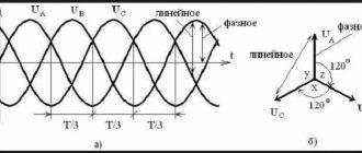
In order to understand how TZNP works, you first need to remember what a three-phase network is. A three-phase network is an alternating sinusoidal current network. In a three-phase circuit, the phases are shifted relative to each other by 120 degrees. This is what it looks like on the graph:
Interesting! The basic ideas and provisions of three-phase power supply networks were developed by Mikhail Osipovich Dolivo-Dobrovolsky. He developed a three-phase asynchronous motor with a short-circuit rotor of the squirrel cage type, with a wound rotor and a starting rheostat, a spark arrester grid, a phase meter, and a dial frequency meter.
If you depict this on a vector diagram, the image will resemble a three-pointed star. Provided that the currents and voltages between the phases are equal, such a system will be called symmetrical. The geometric sum of these vectors is zero.
Important! There are direct and reverse phase sequences. The phases are designated by the letters A, B and C. Then the sequence ABC is forward, CBA is reverse. In this case, the phase shift angle in both cases is 120 degrees. With a zero sequence, the vectors of all phases are directed in the same direction; accordingly, the resulting vector is significantly higher than that (3 times compared to the zero sequence) in the normal state of the system.
In the event of an interphase fault, the currents in all phases will increase, but the system will still remain symmetrical. And zero sequence voltages and currents are equal to zero, as in the normal state of the circuit.
As a result of a single-phase ground fault, the system will become asymmetrical and zero-sequence currents I0 and U0 will be observed. Suppose phase C is closed, then the currents of phases A and B will rush to zero, and in phase C to a third of Is.
I0=1/3(Ik+0+0)
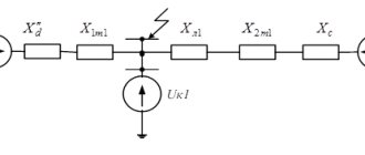
Hence Ik=I0*3. These currents arise under the influence of short-circuit voltage or Uk0 between the terminal of the transformer or generator winding and the point at which the short circuit occurred.
What is a zero sequence?
The vast majority of networks are powered by a three-phase system. Which is characterized by the fact that the voltage of each phase is shifted by 120º.
Rice. 1. Voltage form in a three-phase network
As you can see from Figure 1, diagram b) shows the operation of a balanced symmetrical system. Moreover, if you perform a geometric addition of the presented vectors, then at the zero point the result of the addition will be equal to zero. This means that in 110, 10 and 6 kV systems, which are characterized by grounding of the transformer neutrals, under normal operating conditions there will be no current in the neutral. It should also be noted that geometrically, phase changes can be divided into the following types:
- direct sequence, in which their alternation looks like A – B – C;
- reverse sequence, in which the alternation will be C – B – A;
- and a zero sequence variant corresponding to the absence of a shift angle.
For the first two options, the shift angle will be 120º.
Rice. 2. Direct, reverse and zero sequence
Look at Figure 2, here the zero sequence, unlike the other two, shows that the vectors have the same direction, but their displacement in space between themselves is 0º. A similar situation occurs with a single-phase short circuit, while the currents of the two remaining phases rush to the zero point. This situation can also be observed during phase-to-phase faults, when two of them, in addition to overlap, also reach the ground, and only one phase current will flow at zero.
If a three-phase short circuit occurs in the neutral of the windings, the current will not flow, despite the accident. Because zero sequence currents and voltages will still be absent. Despite the fact that phase voltages and currents in this situation can increase significantly in comparison with the nominal ones.
Operating principle of TZNP
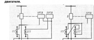
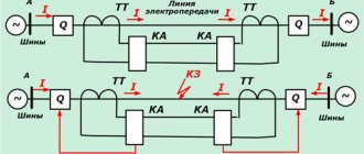
Almost all relay protections, the action of which is adjusted against the appearance of zero-sequence currents, have a similar principle. Consider the following diagram demonstrating the effect of protection.
Schematic diagram of the simplest TZNP
Here is an option for switching on a current relay T, which is connected to the secondary windings of current transformers (CTs) assembled in a star. In this situation, the neutral wire from the star of the transformer windings filters out the zero sequence components if they occur. Provided that the system operates symmetrically, the windings of relay T will be de-energized. And provided that a ground fault occurs in one of the phases, the CT will react to this, causing current to flow through the neutral wire. This will be the very component of the zero sequence, due to which the relay winding T will be excited.
After which a time delay occurs, determined by the parameters of relay B. When the set period of time expires, the current protection sends a signal to the corresponding switching installation U, which disconnects the three-phase network. More complex circuit options may also include a power relay, which allows you to debug the operation of the protection in direction.
In the case of phase-to-phase damage, the symmetry will not be broken, but only the magnitude of the currents will change. And the CTs will continue to compensate for the currents flowing into the neutral wire. The advantage of this scheme is that at maximum operating currents, the protection will still not operate, since symmetry will be maintained.
But if there is a significant difference in the magnetic parameters of the measuring transformers, an imbalance will occur in the system, and an unbalance current will flow through the neutral conductor. This can cause false trips of current protection even in those networks where the rated power supply is observed.
Methods for turning on neutral
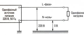
The specificity of the operation of high-voltage (HV) systems is that in the event of a line break or damage, accompanied by a short circuit of a separate wire to ground, leakage currents can reach very large values. Accordingly, the protective measures taken in such networks differ markedly from similar actions in the end-user circuits.
For 6-35 kilovolt networks, the neutral grounding modes listed below are typical:
- direct connection to a charger located directly at a substation or at a high-voltage pole (solidly grounded neutral ground);
- connection through a special arc suppression reactor or compensator;
- using a grounding system for these purposes, in which the neutral is connected through a resistor;
- without connection to the charger within the boundaries of the protected line or object (isolated neutral).
Installation of special compensation elements in the connection circuit of the neutral conductor helps to reduce the capacitive components of the fault currents. During the operation of such a chain, these currents can be neutralized due to a smooth change in the inductance of the coil, the voltage in which has a reverse phase.
Each of these schemes requires the installation of a separate charger on the receiving side, which ensures re-grounding of the neutral and creates safe operating conditions for the overhead line.
Without this device, the switching circuits used cannot effectively perform their protective functions, since if the neutral conductor accidentally breaks, the power equipment of the substations will remain unprotected.
What kind of lighting do you prefer?
Built-in Chandelier
Share
6.10.1. Each DC installation has an insulation monitoring device that signals when the insulation resistance of the DC network falls below the permissible value and allows you to determine the value of this resistance.
6.10.2. If a ground fault occurs in a DC network, you should immediately begin to find it, and all work in the secondary circuits must be stopped, except for work on finding the “ground” and all scheduled switching in the primary circuit must be canceled.
6.10.3. The main method of finding the location of a ground fault is to divide the DC network into parts powered by different sources (batteries, chargers), followed by short-term alternate disconnection of the outgoing lines.
Whenever possible, it is advisable to conduct searches by two persons. A person from the operating personnel must perform switching, and another person must monitor the readings of the insulation monitoring device.
6.10.4. The order of operations must be set out in the Instructions for preventing the development and elimination of technological violations at the substation in compliance with the following provisions:
If a ground fault appears at the moment of turning on any circuit, then this circuit is turned off and checked to see if the short circuit has disappeared.
Ring and parallel circuits are pre-opened.
If there are two DC SBs, the backup power source is switched on to the backup SB and by alternately transferring the connections to this SB, the connection at which there is a ground fault is determined.
If there are two DC sections that can be powered by separate batteries, they are separated by sectioning switching devices and searches are carried out by briefly disconnecting the connections in the section where the ground fault is detected.
The connection at which a ground fault is detected is transferred to power from a backup source, if such a possibility exists. Further searches for the location of the ground fault continue on assemblies or switchboards by briefly disconnecting the outgoing lines connected to these assemblies.
If the ground fault is not found on any of the DC lines, then it is either on the power supply or on the DC buses. In this case, a backup power source is connected to the buses, and the main one is turned off.
Independent actions of substation operating personnel when eliminating technological violations
When making decisions, the SO dispatcher and the operational personnel of the Central Control Center V-D PMES (TsUS RSK) are obliged to take into account the independent actions of the substation operating personnel.
7.2. Lack of communication means not only a disruption of all types of communication, but also the inability to contact the CO dispatcher and the operational staff of the Central Control Center V-D PMES (TsUS RSK) for more than three minutes due to poor audibility and interruptions in communication.
7.3. If there is no communication, along with carrying out the operations specified in this section, all measures must be taken to restore communication. In this case, it is necessary to use any types of communication (long-distance, cellular, departmental, etc.), as well as the transmission of messages through other energy facilities.
Expert opinion
It-Technology, Electrical power and electronics specialist
Ask questions to the “Specialist for modernization of energy generation systems”
Steady-state mode of single-phase ground fault in networks with isolated neutrals. These are devices of types USZ-2 2 individual device connected to a cable-type TTNP, and USZ-3M group device connected in turn to the TTNP of each connection Fig. Ask, I'm in touch!
Zero sequence current protection
But in the presence of a ground fault, the zero sequence of currents becomes unbalanced. A resulting current appears, to which the relay protection reacts.
In systems with an isolated neutral, a special transformer is used to separate these currents, which is placed on the cable.
On a 110 kV power line, this cannot be done and ground fault currents are determined according to a different principle. For this purpose, on conventional current transformers used for relay protection, a separate winding is allocated for each phase. The windings of the phases are connected to each other in series in a special way: the beginning of the next one is connected to the end of the previous one. The current windings of the relay are also included in the same circuit.
Typically, the protected area is divided into sections (zones), approximately like distance protection. The protection itself is multi-stage. The operating current of the first stage is maximum, the time delay is minimum or equal to zero. The next stage operates at a lower current, but with a longer time delay. And so on.
The same protection is installed at the other end of the line. And there can be many lines. The presence of stages makes it possible to ensure the disconnection of the damaged area, as well as to reserve other protections in the event of their failure.
Protection of contact network feeders and RU-3.3 kV
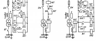
Each of the contact circuit breakers on the feeders of the traction substation must; typically contain primary and backup short-circuit protection. The main ones are maximum and maximum pulse current protection, implemented using polarized high-speed switches. Short-circuit protection must be designed to withstand the maximum loads of normal operation, as well as damage interrupted by locomotive switches or adjacent area switches. The setting is adjusted from the indicated modes by the short circuit safety factor, which for high-speed switches is taken equal to 1.15. Earth protection is used to protect RU-3.3 kV in case of a ground fault. All parts of direct current equipment to be grounded, located in the substation building or in the open part of the substation, are grounded on special internal grounding circuits of direct current equipment (KZOPT) 2 (Fig. 1), which is connected through current relays KA{ and KA2 earth protection circuit substation grounding (SGC) 3, covering almost the entire territory of the substation. In order to avoid shunting of the earth protection relays KA and KAg, it is necessary to ensure during operation that the KZOPT does not touch the grounded cable sheaths and other grounded devices connected to the KZP. If the insulation in a 3.3 kV switchgear is broken, for example, at point K (Fig. 19, a), the ground fault current can reach tens of thousands of amperes. It is almost impossible to perform protective grounding 3 with low resistance, ensuring safe touch and step voltages, with such ground fault currents. Therefore, a short-circuit protection circuit with a resistance of no more than 0.5 Ohm is performed on the open part, and fast-acting earth protection is used to disconnect the fault location.
a - flow of ground fault currents during breakdown of bus insulation + 3.3 kV; b - overhead contact line feeder; c - earth protection circuit for RU-3.3 kV The need to install it is due to the fact that for maximum current protection of transformer 1 of the converter unit, the current during a ground fault in RU-3.3 kV may be insufficient due to the high transition resistance between the short circuit protection devices 3 and traction rail 5, especially in the ground-rail section in the presence of a ballast crushed stone layer. On the other hand, feeder high-speed switches do not respond to the current flowing to the substation from the contact network from substation No. 2 (Fig, b) since they are polarized. The switches of adjacent substations do not turn off due to the small current value for them. Thus, from the above it follows that there is a need to use special protection that responds to insulation breakdown of RU-3.3 kV. When triggered, earth protection disconnects all linear high-speed circuit breakers, Q circuit breakers on the AC side of the converter units and QS mast-mounted disconnectors (Fig., b) of all contact network feeders. The need to disconnect the latter arises when there is a breakdown, for example, of the bushing insulation. After the QFX circuit breaker is turned off, the power supply to the short-circuit point continues from the adjacent substation No. 2; the current of the adjacent substation can be turned off using a QSX motor-driven disconnector. Such a disconnection of current from a neighboring substation is accompanied by partial or complete damage to the disconnector, but it is necessary. The earth protection diagram is shown in Fig., c. When relay KA1 or KA2 is triggered, current flows through the windings of the intermediate relay AL and the indicating relay KN. Relay K Lt becomes self-feeding, closes with its contacts the circuits of the disconnecting coils YA T of the Q switches of all converter units, with other contacts KI, the relay turns off the power supply loop of the holding coils YA of the high-speed switches of the contact network feeders, which are switched off. Relay K 2, having received power through the KLV contact, closes the circuit of the electric motors of the mast disconnectors, which leads to their shutdown. The KLX relay is switched off using the release button SB. Ground fault currents flowing between the external circuit 3 and rail 5 pass through circuit 4 with the least electrical resistance, which is the sheath of power and communication cables. Cables may experience burnout of protective sheaths and current-carrying conductors, especially if there is a delay in operation due to various reasons of earth protection. To avoid this, an ON short circuit is used to connect the suction feeder to the grounding circuit of the KZP. Short circuit 6 is switched on when the earth protection is triggered. Relay KL1 (Fig., a) closes the coil circuit of relay KLV which opens the circuit of electromagnet 9, which holds spring 8 in a compressed state. Under the action of the spring, the core 7 moves down and, with the help of the rod 7, turns on the short circuit. In this case, the resistance of the short-circuit circuit decreases, and, despite the limitation of the short-circuit current by the reactors, it becomes sufficient to trigger the overcurrent protection and disconnect the converter units from the AC buses, and the current of the neighboring substation also increases, which leads to the successful operation of the protection of the corresponding contact line feeder there. . The short circuits are disconnected manually. With lever 11, core 10 moves upward, overcoming the resistance of compressed spring 8, and with rod 7, short circuiter 6 is turned off. In the off state, it is held by the electromagnetic force of coil 9.
How it works
The principle of operation of the TZNP is to turn off the switching equipment in the event of single-phase faults with a certain time delay. The time delay is needed to organize selectivity of protection at different transformer substations.
An example of a zero-sequence current protection circuit is shown in the figure below:
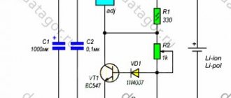
It uses a current relay KA and a power relay KW. To control the current in phases, current transformers (CTs) are used in TZNP. These are special instrument transformers that are placed on a bus or wire. An EMF proportional to the current flowing through the core or bus is induced on its windings.
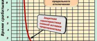
One of the main conditions for the correct operation of the TZNP is that the CTs have identical magnetization curves. This means that they must not only be identical in input and output characteristics, but also be of the same brand. In addition, it is worth noting that the errors in their output parameters should not be more than 10 percent. You can see them in the picture below.
To obtain the currents of the system taken out of balance, the signal is passed through a filter. In real applications, transformer windings are connected to each other. This is called a zero sequence current filter.
In the normal state of the electrical network, the zero-sequence currents are zero, and accordingly, the I outputs of the TZNP filter are also zero. In emergency mode, during a short circuit, the output current is different from zero. The remaining parts of the TZPN are configured in such a way as to exclude false alarms under a certain short-circuit current.
If previously zero-sequence current protection was in the form of relay circuits, now microprocessor terminals for protective circuits are being produced. That is, modern TZNP can be executed on microcontroller circuits.
The considered system is used as backup protection. Thanks to its properties, it is possible to achieve selectivity of operation, where the relay protection and protection of each subsequent TP operates faster than the previous one. Protection is needed to minimize further damage to power lines, transformers, generators, as well as to protect the environment and people who may enter the danger zone.
Finally, we recommend watching a useful video on the topic of the article:
Now you know what zero sequence current protection is, how it works and what it is needed for. If you have any questions, be sure to ask them in the comments below the article!
2. Current directional zero sequence protection.
Protections that use only one NP current signal, despite their simplicity, have significant drawbacks that will lead to their non-selective actions . In the course of further improvement of such protections, two signals began to be used - current and voltage NP to determine the direction. A large number of directional protections respond to the direction of zero-sequence power in steady state. The sensitivity of such protections is higher than non-directional ones, since their operation current is detuned only from the unbalance current in the maximum operating mode, and detuning of the protection from the line’s own capacitive current is not required, since it is detuned in direction from this current. A common disadvantage of this type of protection is its non-selective action or failure to operate during intermittent arc faults .
Basic transformer protection
Any relay protection of a transformer is aimed at triggering in the event of damage or abnormal operation of this device. It should be noted that some of them are aimed at instantaneous shutdown in the event of an accident, while others only provide a warning signal to personnel. In turn, the staff already acts according to instructions that are developed directly and individually for each supply circuit and distribution substation. In order to see what type of accident occurred, signal relays (blinker) are used in parallel, which must be signed in accordance with the rules.
Grounding operation in case of electrical equipment faults
Equipment malfunction means damage to the insulation and the occurrence of a phase in the device housing.
If parts of the equipment are energized, but are not protected by grounding and RCD, a person unaware of the danger may receive an electric shock. In the second option, the current leakage may not be significant; the equipment protection device will not react to the voltage and will not turn off the device. The person may receive a minor blow.
If the housing is not grounded, but the RCD is installed, it will operate 0.02 seconds after a person touches the device body. This time is not enough to cause harm to health.
The most effective scheme from a safety point of view is the presence of grounding and an RCD. If a current leak occurs and passes into the ground, the RCD reacts and turns off the device.
terms of Use
Relays AL-4-1, AL-4-2 must be installed in enclosed spaces, where the temperature can vary from -40 to +55 ºС, and the relative humidity of the ambient air is 80% at 25 ºС.
The environment must be non-explosive and free from dust and gases that could destroy the relay insulation. Vibration of the relay mounting points should be no more than 3 g in the frequency range up to 15 Hz and no more than 1 g in the frequency range up to 100 Hz.
The relay can be installed on a plane in any position with protruding mounting with front or rear connection of wires. To connect the wires from the rear, you need to remove the covers from the terminals and move the screws and washers to the same terminals on the reverse side.
The relays must withstand a continuous supply voltage equal to 1.2 times the rated value.
Specifications
| Options | Values | |
| Rated supply voltage | ~100-110V, 50 Hz and ~/=220V (in one version) | |
| Rated input current | 0.16 A, 50Hz | |
| Response setting range | from 0.02 to 0.2 A with resolution of 0.002 A | |
| Relay response time at current equal to 3 Iset | no more than 0.04 s; for relay AL-4-1 - adjustable in the range 0.1-10s or 0.3-30s | |
| Relay return ratio | not less than 0.9 | |
| Accuracy class | 5 | |
| Switching current | in DC circuits | no more than 60 W at τ=0.005s and no more than 30 W at τ=0.02s; |
| in AC circuits | no more than 300 VA at cosφ=0.5. | |
| Degree of protection | shell | IP 40 |
| contact pins | IP 20 | |
| Continuously permissible contact current | no more than 4A | |
| Mechanical durability of the relay | at least 100,000 cycles | |
| Switching durability of the relay | at least 20,000 cycles | |
| Average service life | 12 years | |
| Relay weight | no more than 0.8 kg | |