Drawing up direct, reverse and zero sequence diagrams
positive sequence circuit is a common circuit that is constructed in any symmetrical mode.
negative sequence circuit is similar in structure to a positive sequence circuit, since the circulation paths of negative sequence currents are the same as those of positive sequence currents. The difference between them is that in a negative sequence circuit the emf
of all generating branches are assumed to be equal to zero and, in addition, it is assumed that the negative sequence resistances of synchronous machines and loads are practically constant and do not depend on the type and conditions of the asymmetry that has arisen, as well as on the duration of the transient process.
The beginning of a direct or reverse sequence circuit is considered to be the point at which the free ends of all generating and loading branches are combined; this is the zero potential point of the corresponding sequence circuit.
The end of a direct or reverse sequence circuit is considered to be the point where the asymmetry in question arose.
If it is necessary to take into account capacitive conductivity, the latter should be introduced similarly to the load branch, the potential of the free end of which is equal to zero.
The zero sequence circuit is largely determined by the connection of the windings of the transformers and autotransformers present in the circuit. Zero-sequence currents are essentially single-phase currents split between three phases and returning through the ground and circuits parallel to it.
To draw up a zero-sequence equivalent circuit, it should be assumed that at the point of an asymmetrical short circuit
all phases are short-circuited and a zero-sequence voltage is applied between this point and the ground.
Then, going from the short circuit
alternately in different directions, it is necessary at each voltage level of the original design circuit to identify possible paths for the circulation of zero-sequence currents (circulation of these currents is possible only in those branches that form circuits for closing currents through the ground and circuits parallel to it) and accordingly, determine the elements of this circuit that should be introduced into the equivalent circuit. It should be borne in mind that the zero-sequence resistance of the transformer on the side of the winding connected in a triangle or star with an ungrounded neutral is infinitely large, therefore transformers with the indicated connection diagrams and all the elements of the original design circuit located behind them are not included in the zero-sequence equivalent circuit .
Circulation of zero-sequence currents is possible only if the transformer winding is facing the calculated short-circuit point
, connected in a star with a grounded neutral.
The resistance through which the neutral of the transformer, generator, motor, load is grounded must be tripled in the zero-sequence circuit.
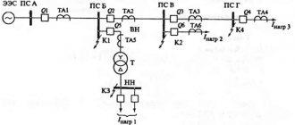
We will consider the procedure for drawing up equivalent circuits for sequences with an asymmetrical short circuit for the initial design diagram of the electrical installation shown in Fig. 9.11.
Rice. 9.11. Initial design diagram of the electrical installation
The equivalent circuit for the first sequence is shown in Fig. 9.12. In the circuit, the resistance of the overhead line for currents of the first sequence is XL1=Xud1ˑL, where Xud1 is the resistivity of the first sequence of the overhead line, U
k1 – first sequence voltage at the
short circuit
; the parameters of the remaining circuit elements are the same as when calculating symmetrical short circuits.
Rice. 9.12. First sequence equivalent circuit
Fig.9.13. Converted circuit
first sequence substitution
In the transformed equivalent circuit of the first sequence shown in Fig. 9.13:
Loop Current Equation for a Transformed Positive Sequence Equivalent Circuit
The equivalent circuit and the converted negative sequence circuit are shown in Fig. 9.14 a
,
b
.
The loop current equation for the converted equivalent circuit will be written as:
Rice.
9.14. Reverse sequence substitution circuit: a
– original;
b
– transformed
The negative sequence resistances in the equivalent circuit are the same as for the positive sequence except for the resistance of the synchronous generator.
Negative sequence emf for SG and system generators cannot exist, because this would mean that the generators would have to change the direction of rotation of the rotors, which is physically impossible.
The equivalent circuit and the converted zero sequence circuit are shown in Fig. 9.15.
In the equivalent circuit, Xl0 = Xud0 · L is the resistance of the overhead line to zero-sequence currents, Xt10, Xt20 are the resistance of transformers to zero-sequence currents. In the converted circuit, the equivalent zero-sequence resistance is determined by the formula
Rice. 9.15. Zero sequence equivalent circuit: a
– original,
b
– transformed
Loop current equation for the converted zero-sequence circuit
In the zero-sequence equivalent circuit, the emf
zero sequence sources, as well as in a negative sequence equivalent circuit, are equal to zero.
Determination of symmetrical components in phase and phase-to-phase voltages: calculation, formulas
Reverse sequence
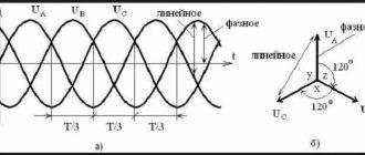
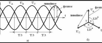
In Fig. P6.1 is depicted in the form of a star of the system of vectors of phase-to-phase voltages UАВ, UВC, UCA and direct voltages UАВ (1), UВC (1), UCA (1) and reverse UАВ (2), UВC (2), UCA (2) sequences . The vector UAB (1) is taken as the real axis. Vector UAB (2) is shifted relative to vector UAB (2) by an angle ϕ2. Vectors UВC (2) and UCA (2) are shifted relative to vectors UВC (1) and UCA (1) by angles ϕ2 – 120° and ϕ2 + 120°, respectively.
Rice. P6.1. Phase-to-phase voltages and their symmetrical components
The connection between phase-to-phase voltage modules UАВ ≠ UВC ≠ UCA and voltage modules of direct U1 = UАВ (1) = UВC (1) = UCA (1) and reverse U2 = = UАВ (2) = UВC (2) = UCA (2) sequences is expressed a system of three equations containing three unknowns – U1, U2 and ϕ2:
By squaring each equation of the system (A6.1) and using trigonometric formulas for cosines and sines of sums and differences of arguments:
we obtain a system of equations:
To eliminate the values U1 2 and U2 2, subtract the third equation from the first and second equations and obtain a system of two equations:
Determining the value of U2 from each equation (A6.4) and equating the resulting expressions, we obtain:
which directly follows:
If the denominator of formula (A6.6) is less than zero, 180° must be added to the angle ϕ2.
To simplify the writing of subsequent equations, we introduce the following notation:
From the relationship of trigonometric functions and taking into account the accepted notations we have:
From the second equation (A6.4) we have:
Substituting (A6.9) into the first equation (A6.4), we obtain an expression for cos ϕ2 in terms of other quantities:
Equating (A6.8) and (A6.10), we obtain the relationship between the quantities U1 and U2:
Substituting (A6.8) and the second equation (A6.11) into the first equation of the system (A6.3), we obtain a biquadratic equation:
the solution of which gives the final formula:
If we substitute not the second, but the first equation (A6.11) into (A6.3), we obtain a formula for U2, the right side of which completely coincides with (A6.13). This is not surprising, since formulas (A6.3) are invariant with respect to the quantities U1 and U2: when U1 is replaced by U2 and U2 by U1 at the same time, the formulas do not change. Therefore, when there is a “+” sign in front of the internal root in formula (A6.13), it 402 determines the quantity that has a larger value, and when there is a “–” sign, a smaller one. Since physically U1 > U2, the general formula has the form (8.6). These formulas were first derived in 1985 [44].
To check the correctness of the obtained formulas, let us take as an example the values of phase-to-phase voltages corresponding to U1 = 400 V; U2 = 40 V and ϕ2 = 30°. Substituting these values into formulas (A6.1), we obtain: UAB = 435.1 V; UBC = 402.0 V; UCA = 365.9 V.
Taking these voltages as initial data, using formulas (8.6) and (8.7) we obtain: U1 = 400 V; U2 = 40 V; ϕ 2 = 30°, which indicates the correctness of the formulas.
Transformations of equations (A6.1) can be carried out in various ways. For example, in [45] a formula is given for the negative sequence voltage, which also uses quantities (A6.7) and determines the value of U2 as a percentage of U1 (the formula for U1 in [45] is not given, so the value of U2 in volts is not defined):
Substituting the values a4 and a2 into the formula, we get U2 (%) = 10%.
Zero sequence
The phase voltages contain all three sequences. The system of equations connecting the modules of phase voltages with the modules of positive, negative and zero sequence voltages has the form:
There are five unknowns in equations (A6.15): U1ф, U2ф, U0, ϕ2ф and ϕ0. It is impossible to obtain expressions for them from a system of three equations. Therefore, it is impossible to calculate the components of the positive, negative and zero sequences of phase voltages based on measuring only phase voltages. It is necessary to use the direct and negative sequence components of phase voltages obtained from the calculation of phase-to-phase voltages: U1ph = U1 / 3 and U2ph = U2 / 3. The angle ϕ 2ph between U2ph and U1ph is related to the angle 403 between U2 and U1. the relation ϕ 2ф = ϕ 2 + 60°, that is, it is also known. In this case, only two unknowns remain in (A6.15): U0 and ϕ 0 . The system of equations turns out to be redundant - it is enough to use any two equations. Nevertheless, we will continue operations with all three equations, since deriving the final formulas turns out to be simpler.
To simplify the writing (A6.15) of the product and sum of already known quantities and which are constant when deriving relations for U0, we denote:
To simplify further transformations, we exclude the value U0 2. To do this, subtract the second from the first equation, and the third from the second and obtain a system of two equations:
To simplify the notation, we denote the quantities in parentheses of formulas (A6.20), which are constants:
In this case, formulas (A6.20) will take the form:
Expressing U0 from each equation and equating the right-hand sides of the resulting formulas, we obtain:
We write the equality of the right-hand sides of formula (A6.23) in the form:
Dividing the numerator and denominator of the right side of the equality by cos ϕ0, we get:
After determining the angle ϕ0, the value of U0 is determined by substituting it into any of the equations (A6.23).
The above calculation algorithm assumes the determination of U0 after the preliminary determination of ϕ0. Substituting (A6.25) into the relations
and then in (A6.23), it is possible to obtain a formula that directly determines U0 through phase and phase-to-phase voltages, but it turns out to be overly cumbersome. Therefore, it is more expedient to use formulas (A6.25) and (A6.23) sequentially.
Substituting expressions (A6.16) into (A6.21), we obtain formulas that directly connect the quantities a, b, c, d, e, f with the direct and reverse sequence parameters determined at the first stage (both in phase and phase-to-phase voltages):
To check the correctness of the obtained formulas, we take as an example the values of phase voltages corresponding to U0 = 20 V, ϕ0 = 60° and previously obtained from the calculation of phase-to-phase voltages U1ph = 400 / 3, U2ph = 40 / 3 and ϕ2ph = ϕ2 + 60° = 30 ° + 60° = 90°. Substituting these values into formulas (A6.15), we obtain:
Using (A6.26) we calculate the coefficients:
Substituting these data sequentially into (A6.24), (A6.25) and (A6.23), we obtain:
which confirms the correctness of the calculation formulas.
All the above formulas were obtained based on the original systems of equations relating phase and phase-to-phase voltages with the voltages of symmetrical components and the angles between them. Another way to derive similar formulas is based on the use of relationships between the sides and angles of oblique triangles.
There are well-known formulas derived by F. F. Karpov (given in the “Guidelines for monitoring and analyzing the quality of electricity in general-purpose electrical networks”, published in [46]), according to which the positive and negative sequence voltage parameters are determined as follows:
where U′ and U″ with the corresponding subscripts are the longitudinal and transverse components of the vectors U1 and U2; ϕ1(2)–AB are the angles of vectors U1 and U2 with respect to the vector UBA. If U′ 1(2) < 0, 180° must be added to ϕ1–AB and ϕ2–AB. The angle of vector U2 relative to vector U1 is determined by the difference ϕ2–1 = ϕ2–AB – ϕ 1–AB.
To determine the values of U 1(2) and U 1(2), first calculate the auxiliary quantities:
and then substitute them into the formulas:
In formulas (A6.29), when determining the components of vector U1, the “+” sign is taken, and the vector U2 is taken with the “–” sign. The values of the direct and reverse sequences determined from these expressions for the conditions of the example completely coincide with those determined above, while the angles ϕ1–АB = –2°40′; ϕ2–AB = 27°20′ and ϕ2 = ϕ2–AB – ϕ1–AB = 30°.
Zero sequence voltage parameters in accordance with [46] are determined by the formulas:
To determine the values of U′ 0 and U″ 0, in addition to the values (A6.28), auxiliary quantities are calculated:
and then substitute all auxiliary quantities into the formulas:
When converting the relationships between the sides and angles of oblique triangles, various techniques can be used. The resulting calculation formulas may have different appearances, but if no assumptions were used in their derivation (for example, neglecting any components due to their obviously smallness compared to the others), then all formulas give identical results.
In particular, GOST 13109–97 [47] provides formulas (in the formula for U0 the signs in front of X and Y are corrected):
Unfortunately, these relatively simple-looking expressions do not have formulas for determining the angles between the vectors of symmetrical components. For the purposes of comparing the calculated values with the standards of the standard, angles are not needed, however, when choosing means of mode balancing (for example, calculating the power of capacitors by phase), they cannot be avoided.
All the above formulas are exact algebraic expressions that give absolutely identical results. When expressly assessing symmetrical components based on measurement results without using complex formulas, you can use approximate relationships:
For different values of the angle ϕ2, the coefficient in the second formula does not go beyond 0.575–0.665, therefore the maximum error in the approximate determination of U2 does not exceed 7.3%. The error in the approximate determination of U1 is even smaller, and the average value of phase-to-phase voltages is always slightly greater than the actual value of U1. This excess depends on the value of U2 and is well approximated by the formula δU1 (%) = 0.0025 U2 (%) 2. For example, with U2 = 2% the excess will be only 0.01%, and with U2 = 10% - 0.25%.
For the given example, using formulas (A6.35), we obtain: U1 = 401 V and U2 = 42.9 V (U2 (%) = 10.7%). If we clarify the value of U1 by subtracting the excess δU1 = 0.0025 ∙ 10.72 ∙ 401 = 1.15 V, then U1 = 399.85 V, that is, U1 is determined with an error of less than 0.04%.
Balancing phase and phase-to-phase voltages
The need for such balancing is justified in clause 8.1.2. The form of equations for adjusting the measured voltages in order to bring them to a physically existing system depends on the adopted balancing criterion. The following criteria are possible.
- Leave the five voltages unchanged, and change the last phase voltage so that it reaches the zero point determined by the other two phase voltages (see Fig. 8.4, c). The validity of this approach is questionable, since it is unclear by what condition the only “inaccurate” voltage that requires correction should be selected.
- Correct all phase voltages, leaving phase-to-phase voltages unchanged. In this case, the question arises: why should phase-to-phase voltages be considered accurate and phase voltages inaccurate?
- Since all six voltages are measured with uncertainty, it seems more logical that all of them should be adjusted. In this case, the direction of correction of phase 409 and phase-to-phase voltages turns out to be different. In the case shown in Fig. 8.4, a, phase-to-phase voltages should be slightly increased, and phase voltages should be reduced, and in the case shown in Fig. 8.4, b, - vice versa. Assuming that all voltages are measured by the device with the same relative error δ, it seems logical that all six voltages should be changed in the same proportion (albeit in different directions). With this approach, the question arises: why is it assumed that when measuring all phase-to-phase voltages, the error appeared in one direction, and when measuring all phase voltages, in the other?
There are questions for each of the approaches that seem to completely demonstrate the illogicality of the approaches considered. Nevertheless, the task is not to refute the approaches, but to propose at least one acceptable one, since it is even more illogical to carry out calculations of symmetric components for a physically non-existent system of initial vectors.
The condition for the physical existence of the system is the equality ϕАВ + ϕВС + ϕСА = 360° (in Fig. 8.4, a the sum of the actual angles is more than 360°, and in Fig. 8.4, b – less than 360°).
From the known ratios of sides and angles of oblique triangles, the angle ϕAB is determined by the formula
Similar expressions can be written for the angles ϕВС and ϕСА. The sum of half angles, naturally, should be equal to 180°. Determined from the measured voltages, it will always differ from this value. We characterize the degree of difference by the ratio:
The stress values in formula (A6.37) must be adjusted so that the angles determined by (A6.37) satisfy the condition kϕ = 1. This condition can be ensured with different changes in the angles included in the sum. The criterion for adjusting angles is not obvious: should all angles be adjusted to the same extent, or should smaller angles be adjusted to a greater proportion (or vice versa)? Of the approaches described above, the third has the least disadvantages. Let us derive relations for adjusting stresses based on this approach and the condition for adjusting all angles to the same extent: k / iik ϕ =ϕ ϕ .
In order for the angle ϕAB, determined by formula (A6.37), to become equal to ϕAB, it is necessary to change the voltages UAB, UA, UB in accordance with the equality
Similar coefficients can be determined for the other two triangles. The coefficients will differ from each other, which is explained by the assumption that all angles are adjusted in the same proportion. However, in each triangle, two sides are common to adjacent triangles and cannot be adjusted differently. The only visible solution is to apply the average correction factor kU = (kU AB + kU BC + kU CA) / 3 to all voltages.
For example, assume that the following voltages are obtained as a result of measurements:
Having calculated the corresponding angles using formula (A6.37) and similar formulas for other triangles, we obtain:
The sum of the angles is 196.2°, that is, the system corresponds to the case of Fig. 8.4, b. It is necessary to reduce the angles by dividing them by the coefficient kϕ = 196.2 / 180 = 1.09. In this case, the values of the angles to / 2 ϕAB and the corresponding tangents will be:
Substituting these values of tg ϕ into formula (A6.40) and into similar formulas written for other phase-to-phase and phase-to-phase voltages, we obtain:
Applying kU avg to the measured voltages, we obtain:
If we determine the angles for this stress system using formulas like (A6.37), then their sum will be (65.1° + 64.8° + 48.3°) = = 178.2°, that is, instead of exceeding by 16, 2° the amount became 1.8° lower than required. If desired, you can do another iteration.
To obtain a formula for adjusting stresses for the case when the initial sum of angles is less than 180° (Fig. 8.4, a), it is necessary in formula (A6.39) to replace division by kU with multiplication, and vice versa. However, due to the slight difference in kU values from unity, the result will differ insignificantly. Therefore, in this case, you can use formula (A6.40); in this case, the kU values will be slightly less than unity and will lead to the necessary increase in phase-to-phase voltages and a decrease in phase voltages.
When using the given algorithm, the set goal - the creation of a physically existing system of vectors - is achieved. However, questions remain about the validity of the adopted criterion - changes in phase and phase-to-phase voltages in different directions. Taking into account the random nature of the measured values, it seems most reasonable to use the criterion of the minimum sum of squared deviations of the relative values of the corrected voltages from their measured values:
while simultaneously satisfying the condition imposed on the sum of angles. There is currently no solution to such a system of equations.
In general, the algorithm for calculating the parameters of symmetrical components consists of the following stages:
- balance phase and phase-to-phase voltages;
- calculate the parameters of the direct and reverse sequence of phase-to-phase voltages using formulas (8.6) and (8.7) or other similar formulas;
- using formulas (8.8) calculate the coefficients a, b, c, d, e, f; using formulas (8.9) – (8.11) the zero sequence parameters are calculated.
What is zero sequence voltage? Schemes, application, physical meaning
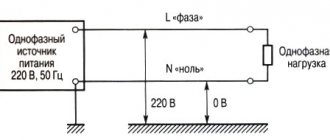
The three-phase voltage system is symmetrical in normal operation. But as soon as a short circuit occurs, the symmetry is broken. For the convenience of recognizing types of short circuits and carrying out calculations, the method of symmetrical components is used. According to it, any three-phase system from the moment of short circuit can, for convenience of calculations, be represented as the sum of the voltages of three symmetrical systems:
All of them are imaginary quantities that do not exist in reality. But with the help of some tricks they can be made really tangible and put into practice.
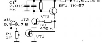
Contents Previous § NextDevices that extract voltage of the desired sequence from a three-phase voltage system are called filters. Let's consider one of these devices, used in practice to detect ground faults.
Chapter thirty-eight
ASSYMMETRICAL OPERATING MODES OF SYNCHRONOUS GENERATORS
§ 38-1. The action of symmetrical current components in a synchronous machine and the parameters of positive, negative and zero sequence
Preliminary remarks.
In practice, there are cases when powerful single-phase consumers disrupt the symmetrical load of the phases of synchronous generators (traction substations of railways electrified on alternating current, etc.).
Even more often, although briefly, an asymmetrical load on generator phases occurs during asymmetrical short circuits in
electrical networks: with a single-phase short circuit - between the linear and neutral wires, with a two-phase short circuit
in case of a short circuit - between two linear wires and in case of a two-phase short circuit to neutral - between two linear and neutral wires. The role of the neutral wire in high voltage networks is played by the ground, since the neutral points in such networks are usually grounded.
Although asymmetrical short circuits exist for a short time, since the damaged sections of the networks are switched off by relay protection, they have a strong impact on the operation of generators and the network as a whole. During sudden asymmetrical short circuits, transient processes also occur, but below, in order to identify the main features of the phenomena, first of all, established asymmetrical operating modes are considered.
A general method for studying asymmetrical modes is the method of symmetrical components, in which an asymmetrical system of currents is decomposed into symmetrical components and the effect of the latter is taken into account separately. In this section we will consider the effect of currents of equal sequences in a three-phase synchronous machine.
Positive sequence currents and resistances.
With a symmetrical load on a synchronous generator, only positive sequence currents exist.
Therefore, what is stated in Chap. 32 and 33 relate to the operation of synchronous machines with positive sequence currents and the synchronous resistances xd
and
xq
are the resistances of the synchronous machine for positive sequence currents.
The most significant feature of the normal operation of a synchronous machine with positive sequence currents is that the rotor of the machine rotates synchronously with the field of positive sequence currents or the armature reaction field and therefore this field does not induce any currents in the inductor circuits. For this reason the resistance xd
and
xq
are large.
Using the terminology of the theory of asynchronous machines, we can say that the slip s of the rotor of a synchronous machine relative to the magnetic field of the positive sequence currents of the stator (armature) is zero. Therefore the resistance ha
and
xq
are identical to the inductive reactance of an asynchronous machine at ideal no-load (s =
sx =
0).
The components of this resistance are the inductive leakage reactance haa
and inductive reactance from the fundamental field harmonic in the air gap (for a synchronous machine
Negative sequence currents and resistances.
Let's imagine
that
the armature winding (stator)
of a synchronous machine is powered by a negative sequence voltage
U2. The resulting negative sequence currents create a negative sequence magnetic field that rotates relative to the stator at synchronous speed in the opposite direction, and relative to the rotor rotating at synchronous speed in the forward direction at twice the synchronous speed. Therefore, relative to this field, the rotor slip s2
= 2 and in the field windings, calming windings and in the massive parts of the rotor, secondary currents of double frequency are induced, which cause corresponding losses and heating of the rotor.
In view of what has been said, for the case under consideration everything stated in § 36-1 is valid for s = 2.
The equivalent circuits for negative sequence currents are the circuits in Fig. 36-2 at s = 2. Let us denote the resistance of these circuits at s =
2 letters Zd2 and Zg2.
At Zd2 f
Z92 stator currents contain a fundamental frequency component and, according to expression (36-4), triple frequency currents, the influence of which can be neglected.
The fundamental frequency current is a negative sequence current /2 and is determined by the first equality (36-3) at s = 2:
Therefore, in the first case, in accordance with equality (38-2)
Resistance Z2 according to formula (38-2) corresponds to the case when the stator voltages are sinusoidal and the currents are non-sinusoidal. If significant inductive resistances are connected in series with the stator winding (for example, the resistance of transformers and transmission lines), then the negative sequence currents are sinusoidal and the stator winding voltages are non-sinusoidal . In this case, as can be shown,
In this case, there are no higher harmonics of current and voltage.
Due to the shielding effect of secondary currents, resistance *2 is significantly less than xa
and
xq
(see Table 32-1).
Resistances 22, x2 and h
can be determined from the measured values of
U2,
/2 and active power consumption
P2,
if synchronous
car to the source
symmetrical voltage system and rotate the rotor against the field
at
synchronous speed. To avoid overheating of the rotor, it is necessary that /2 = (0.2 - g - 0.25) / n. If the machine does not have calming windings and circuits, then to obtain more correct results it is necessary to isolate the main harmonics of current and voltage from the oscillograms.
Zero sequence currents and resistances.
The zero-sequence currents of the stator winding /0 create in the air gap only pulsating fields of harmonics v = = 3, 9, 15..., and the fundamental harmonic of the field will be absent (see § 22-2). These field harmonics induce excitation and calming currents in the windings, the magnitudes of which are relatively small.
Zero sequence resistance
Zero sequence inductive reactance x0
due to the absence of the fundamental harmonic field, it is relatively small (see Table 32-1) and is determined by the slot and frontal scattering fields of the stator winding and the above harmonics of the field in the gap.
The zero-sequence active resistance r0
as a result of losses caused by field harmonics in the rotor is slightly greater than the active resistance of the stator winding
r,
but the difference
r0
-
r
is small and r0
!=& r.
The torque created by currents /0 is practically zero.
Resistance r0, x0
and,
r0
can be determined experimentally if, when the machine rotates at a synchronous speed, the series-connected phases of the stator winding are supplied with current /0.
The indicated resistances are determined in exactly the same way as for a transformer (see § 16-1).
§ 38-2., Operation of synchronous generators with an asymmetric load
The stator winding of synchronous generators is usually connected to a star, and the zero point in small machines is isolated, and in large machines it is grounded through a large resistance in order to provide relay protection against ground faults. Therefore, zero-sequence currents are either absent or very small.
Because of this, with an asymmetrical load of synchronous generators, in addition to positive sequence currents, practically only negative sequence currents exist.
I The latter cause a number of undesirable phenomena in the machine and make the operating mode of the machine difficult.
Energy loss and rotor heating.
Double frequency currents induced in the rotor by the magnetic field of the negative sequence stator cause unnecessary losses in the rotor and its heating, as well as a decrease in the efficiency of the machine.
The currents induced by the reverse field in the calming windings of salient-pole machines and in the massive rotor of turbogenerators can be very significant, and the active resistance to these currents under the influence of the surface effect will be large.
Therefore, with significant load asymmetry, excessive and dangerous heating of the damper windings and massive rotors occurs.
The high temperature of the turbogenerator rotor body causes dangerous deformations of the rotor and the possibility of damage to the insulation of the field winding. Heating the calming winding of a salient-pole machine has little effect on the temperature of the field winding due to the distance of these windings from each other and the better cooling conditions for the field winding of salient-pole machines.
The currents induced by the reverse field in the field winding are smaller due to the higher leakage resistance of this winding. Therefore, in salient-pole machines, the additional heating of the field winding with an asymmetrical load is small.
Vibration.
As a result of the interaction of the excitation flux and the negative sequence flux of the stator, as well as the positive sequence field of the stator and the field of double-frequency currents of the rotor, under an asymmetrical load, alternating torques and tangential forces, pulsating with a frequency of 2/x, act on the rotor and stator.
In addition, due to the same reasons, pulsating radial forces of attraction and repulsion arise between the poles of the stator and rotor fields, tending to deform the stator and rotor. These forces cause vibration of machine parts, noise and weakening of the press fit of the stator core. Dual-frequency pulsating forces due to fatigue phenomena can also have a detrimental effect on the strength of welded joints, especially in the presence of welding defects. All of these factors, naturally, are stronger the greater the load asymmetry.
Distortion of stress symmetry.
Negative sequence currents cause a voltage drop in the phases of the stator winding
Z2/2, whose vectors are oriented differently relative to positive sequence voltages in different phases.
As a result, the symmetry of the generator voltages is distorted and the voltages of the more loaded phases will be lower. This worsens the operating conditions of receivers, especially asynchronous and synchronous motors.
In machines with calming windings and massive rotors or poles, Z2 is smaller, as a result of which they have less voltage symmetry distortion. Physically, this is explained by the fact that in such machines the negative sequence flow of the stator is largely drowned out by the currents induced in the rotor, and therefore this flow induces smaller e.g. in the phases of the stator winding. d.s.
Higher harmonics of currents and
voltages.
As was established above, due to the inequality of resistances along the longitudinal
(Zdi)
and transverse (Z?2) axes, a third current harmonic appears with a frequency of 3/x. A particularly strong distortion of the shape of the current curve occurs during asymmetrical short circuits, since in this case the smoothing influence of external inductive reactances disappears or is weakened. As an example in Fig. Figure 38-1 shows the current waveform for a two-phase short circuit.
Higher current harmonics can cause dangerous resonance phenomena if there are capacitances in the stator winding circuits (for example, capacitance of long transmission lines, etc.).
As a result of voltage resonance at the terminals of the stator winding, voltages of high frequencies arise, which can exceed the rated voltages many times and damage the insulation of the machine. This is one of the reasons that powerful hydrogenerators operating on long transmission lines are usually equipped with dampening windings. If there are damper windings Zrfa m
Z?2 and
x»d
~
x»q,
as a result of which in this case the currents remain sinusoidal and the danger of these overvoltages disappears.
The permissible load asymmetry is limited primarily by the need to prevent dangerous heating of the rotor, as well as vibration of the machine.
According to GOST 183-66, long-term operation of turbo and hydrogenerators with
asymmetrical load, if the phase currents do not exceed the rated values and the current difference in the phases does not exceed 10% of the rated phase current.
§ 38-3. Asymmetrical short circuits
Basic equations. Let us consider established asymmetrical short circuits at the terminals of a generator with a star connection of the windings, assuming that they occur during idling operation, and determine the magnitude of the short circuit currents. To do this, let us first compile equations connecting currents (/], /2, /0), * resistances (Z\,
22, Zo) and voltages
(Ult U2, Uo)
of different sequences, and
Ui, U2
and
Uo
are the components of the phase voltages
Ua, lib, Uc
at the short circuit (Fig. 38-2).
The excitation current induces only e. d.s. positive sequence 1 Ei
=
E,
and therefore £2 =
Ea
= 0. Since the phase circuits up to the point of the short circuit are symmetrical, the voltage equations for different sequences are independent of each other and for phase
a
have the form
In addition, there are the following dependencies between phase currents and voltages and their symmetrical components:
properties of each type of short circuit, it is necessary to create three additional equations.
First, it is advisable to determine the symmetrical components of currents and voltages, and then, using equations (38-13) and (38-14), find the phase quantities.
From equations (38-12) the symmetrical stress components can be determined:
If we substitute these values Ult (]r, ya
into equations (38-14), then the latter take the form
According to expressions (38-16), the phase voltages are equal to e. d.s. phases E, a2E
and
aE
minus the voltage drop from currents of different sequences in the resistances of the corresponding sequences.
Rice. 38-3. Schemes of single-phase (a), two-phase (b) and two-phase to neutral (c) short circuit of a synchronous generator
Equations (38-12) - (38-16) are valid not only for asymmetrical short circuits, but also for the general case of an asymmetrical load of a synchronous generator. However, below they will be used to study asymmetrical short circuits.
Single-phase short circuits.
In this case, according to the diagram in Fig.
38-3, a,
or after substituting the values of a and o2
Rice. 38-6. Vector diagrams of currents (a)
and voltages (b) with a two-phase short circuit to neutral
Complex replacement schemes. The results obtained make it possible to construct very simple complex equivalent circuits for various types of short circuits, which include resistances of various sequences and determine the relationships between currents and voltages of various sequences.
In Fig. 38-7, a
Based on equality (38-22), such a circuit is presented for a single-phase short circuit.
The generator is shown as a source of energy. d.s. E,
Z%
is connected in series with it and between points
M
and
N,
conventionally representing the location of the short circuit, Z2 and Zo are connected in series.
Below we will see that this circuit structure will remain the same for other types of short circuits, but at the location of the short circuit, between points M and N,
other resistance values will operate.
It is obvious that the diagram in Fig. 38-7, a
is quite consistent with equality (38-22). In this diagram, in addition, based on equations (38-15), it is shown between which points of the circuit voltages of different sequences act. As in this one,
and in other cases voltage Ui
acts between the conventional short circuit points
M
and L', and
U2
and
Uo
are equal to the voltage drops in the resistances Z3 and
Zo, respectively.
In Fig. 38-7, b
based on equality (38-28), a complex equivalent circuit for a two-phase short circuit is presented, and the voltages indicated there are also determined by equations (38-15).
In Fig. 38-7, c
shows a diagram for a two-phase short circuit to neutral, corresponding to equalities (38-36), as well as (38-15) and (38-35).
Finally, Fig. 38-7, d,
according to what is stated in § 33-2, shows a diagram for a three-phase short circuit. In this case
Rice. 38-7. Complex equivalent circuits for single-phase (a),
two-phase (b), two-phase to neutral
(c)
and three-phase (d) short circuit of a synchronous generator
Having established the type of complex equivalent circuits, you can not solve the equations, as was done above, but write down expressions _ for 1 and h> h
and
Ult U2, й0
directly based on equivalent circuits. If there is no resistance of any sequence in the circuit, then the corresponding current and voltage components are equal to zero. It can be shown that the circuits in Fig. 38-7 are valid not only for the simplest short circuits considered, but also for asymmetrical short circuits in a complex network, and in the latter case, Z1 ( Z2 and Zo should be understood as the resistance of the entire network for the currents of the corresponding sequences.
Comparison of different types of short circuits .
If the resistance of the neutral wire is zero and short circuits occur at the terminals of the machine, then
r1
> r2 > r0 or, if active resistances are neglected, Zj =
x^
> g2 = =
x%
> r0 =
x0
(see Table 32-1).
In this case, based on equalities (38-23), (38-29), (38-37) and (38-40), it can be established that for the same E
there will be ^ki > ^kg > ^kgo > ^kz- Physically this can be explained by the fact that in a single-phase short circuit, the demagnetizing reaction of the armature is created only by the current of one phase and therefore in this case the value of the short circuit current is the largest, and as the number of short-circuited phases increases, their currents decrease. On the other hand, as can be seen from the diagrams in Fig. 38-7, for positive sequence currents the reverse relationships are valid: the largest value /x corresponds to a three-phase, and the smallest to a single-phase short circuit. In accordance with what is said in Fig. Figure 38-8 shows the characteristics of short circuits.
When calculating the values of short-circuit currents, you can always use relations (38-24). Note that, in addition to the currents discussed above
Rice. 38-8. Characteristics of asymmetrical and symmetrical short circuits of a synchronous generator
fundamental frequency, with an asymmetrical rotor (absence of calming windings and circuits), higher current harmonics also arise.
Determination of negative sequence resistances. Data from the two-phase short circuit experience are used to determine r2, x2 and r2.
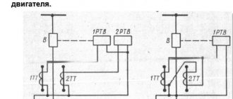
In Fig. 38-9 shows diagrams of a two-phase short circuit with the inclusion of devices for measuring the necessary quantities, the designations of which are indicated next to the symbolic images of the devices.
Rice. 38-9 Circuits for determining negative sequence resistance based on two-phase short circuit experience
For the impedance module, according to the readings of measuring instruments, based on equalities (38-32) for the circuits in Fig. 38-9, a, b i c
respectively
WE WILL GET
GOST 10169-62 recommends using the diagram in Fig. 1 for testing synchronous machines. 38-9, in
and the last of relations (38-41) and (38-42). It should be borne in mind that in the absence of calming windings and circuits, the resulting
the results will be inaccurate due to the presence of higher harmonics. To take into account the influence of these harmonics, corrections can be introduced, which are not discussed here. Determination of zero sequence resistances. For this purpose, data from the experience of a two-phase short circuit to neutral, carried out according to the diagram in Fig. 38-10. In accordance with equality (38-39)
Rice. 38-10. Circuit for determining zero-sequence resistances based on experience of a two-phase short circuit to neutral
Sudden asymmetrical short circuits.
As with a sudden three-phase short circuit, in this case also aperiodic and periodic currents arise in all windings. In case of sudden asymmetrical short circuits, the periodic armature currents will contain components of the same sequences /x, 72, /0, as in the case of established short circuits. As follows from a more detailed consideration of this issue, the amplitudes of the initial values of periodic armature currents can be calculated from equalities (38-23), (38-29) and (38-37), if we substitute Z\, 2r
and Zo respectively
jxd
(or
jx'd), jx2
and
]x0
and multiply the results by
Yi,
and the amplitudes of the steady-state values of periodic currents are calculated in the same way, but instead of
]x»d
(or
jxjfi
it is necessary to substitute /%• The difference between the initial and final values periodic currents attenuate with time constants
T'd, Ta,
as with a three-phase short circuit, but for asymmetrical short circuits these constants have different values.The initial values of the aperiodic armature currents are equal in magnitude and opposite in sign to the periodic currents and also attenuate with the corresponding constants time.
Sudden asymmetrical short circuits are discussed in more detail in special manuals [68, 69, 72, 73, 75, 76, 79J.
Contents Previous § Next