Cable testing or selection of the required cable pairs at the cross-connect and in the coupling is an integral part of the work of any specialist associated with cable infrastructure. These tasks have to be solved in local networks and in data centers, when servicing cable television systems and security/fire alarms. This cannot be avoided when servicing subscriber lines of telecommunications operators.
That is why devices for testing cable lines are so popular and have found their place in the range of many manufacturers of measuring equipment represented on the Russian market. You've probably come across names like:
- cable continuity;
- test set;
- non-contact induction device for testing lines;
- testing the cable with a probe;
- headset for dialing;
- device (tester, device) for testing wires;
- device for network tone testing;
- tester with tone generator, etc.
By all these names we mean a set consisting of two main components: a tone generator and a receiver (most often an inductive probe). Therefore, the functionality of such a test suite directly depends on the characteristics of its components.
In this article we will look at the features of various test kits and classify them by areas of application.
Special devices
At a professional level, two tools are used for dialing: a tester and a multimeter.
The first is a multifunctional device, which can also be used to connect cables and wires.
Algorithm for using the classic arrow tester:
- the switch is set to 1 kOhm;
- the fuse turns on;
- the measurement buttons are pressed under reverse and alternating current conditions;
- the probes are connected to the central and right terminals, this will allow you to measure the resistance;
- the probes are closed to each other.
The arrow should move to the right.
The advantage of the tester is its reliability. Flaws:
- complexity of management;
- large size;
- there is an error in operation when the battery is discharged.
For your information. In fact, a tester is a device aimed at accurate measurements. When testing wires, it is an indicating device.
The multimeter is the most commonly used instrument. Every electrician has one. There are many modifications of it on the market. The principle of their operation is the same. Some parameters may be different, for example:
- location of management and control bodies;
- measurement range.
Working with a multimeter is similar to using a tester. It is necessary to set the switch to the “Dial” position. The corresponding position is indicated by a diode sign or a buzzer.
If the conductor is intact, the device emits a sound signal. On some models, the sound signal is replaced by a special indicator.
The disadvantage of the multimeter is that the sound signal appears with some time delay. So the probe must be kept fixed on the wire for at least 2 seconds.
For your information. Preference should be given to probes whose rods are gold-plated. They do not oxidize like those made from steel.
For successful dialing, the cheapest multimeter is sufficient.
Wiring continuity tester
Historically, at the initial stage of development of electrical engineering, a tester was called a pointer combined device, which includes:
Pointer combined device Ts 4342-M1. In order to ring a wire with a pointer tester, you need to carefully study the capabilities of the device, how to connect the measuring probes and in what position to put the switches on the control panel.
Familiarize yourself with the discrete division of the scale; the controls and scales are different on devices of different models. Let's consider the wire testing technique using the example of a pointer tester Ts 4342-M1:
- Set the batch switch of measurement modes to the 1 kOhm position, some models have Ohm.
- Turn on the fuse button, protecting the calibrated elements of the device circuit from incorrect connection. If in continuity mode the circuits are energized.
- Press the forward and reverse current measurement mode buttons, two black buttons at the bottom of the control panel;
- Connect the probe wires to the center and right terminals to measure resistance;
- To check the functionality of the device, connect the probes to each other, the arrow on the scale should move from left to right until it stops. Measurements are carried out on a scale marked kOhm, second from the top. If the arrow moves to the right towards zero, the device is working.
The advantages of this tester are reliable protection and measurement accuracy, but in case of continuity, it works as an indicator device. Accurate readings are not required here; the following can be considered disadvantages:
Buy cable testers inexpensively in the VseKablei online store, customer reviews. Large catalog, description, characteristics - Moscow
Pointer combined device Ts 4342-M1. In order to ring a wire with a pointer tester, you need to carefully study the capabilities of the device, how to connect the measuring probes and in what position to put the switches on the control panel.
Expert opinion
It-Technology, Electrical power and electronics specialist
Ask questions to the “Specialist for modernization of energy generation systems”
Cable testing - price in Moscow: price of wire testing - reviews and private advertisements on YouDo In order to test a wire with a pointer tester, you need to carefully study the capabilities of the device, how to connect the measuring probes and in what position to put the switches on the control panel. Ask, I'm in touch!
Dialing methods
There are several ways to ring wires at home:
Using a light bulb and battery. This is the simplest and fastest method. In order to construct such a device, you need to have a light bulb and a battery (several batteries can be connected together), as well as connecting conductors and a probe. In addition, do not forget that the voltage of the light bulb and the battery should be the same, or the battery should have more, but not vice versa. The connecting wire must be long enough to ring the wire from a distance.
In order for the dialer to work correctly, it is necessary to mark the cable in any order. The operating method of such a device is as follows: a wire that comes from the battery is connected to one core, and a light bulb is attached to the probe. Use this probe to touch the conductors at the opposite end of the cable one by one. If the light comes on, it means this wire is connected to the battery.
You can learn how to ring the wires of a light bulb and a battery from this video lesson:
Using a multimeter. This device measures various parameters of the electrical network (for example, voltage, current, resistance). In the house, such a device will be indispensable if you need to check an outlet or switch, check for a break, or find out where the wire goes.
You can test the cable with a multimeter using the following method:
- The dialing function is installed. Depending on which model of device is used, this mode is designated differently. As a rule, it is indicated by a diode.
- Then you need to find the phase in the distribution box. This is done as follows: you need to turn on the power and use an indicator screwdriver to check each cable. We mark the one we need with tape or tape and then determine zero.
- After this, you should find the voltage. To do this, set the multimeter to the “voltage measurement” mode. Using a probe, we check each wire. If the next time you touch the probe, it lights up around 220 V, then the right one has been found.
To check the electrical wiring in the wall for integrity, you need to disconnect the cable from the power source. Set the multimeter to resistance measurement mode. When the probes are closed, zeros should appear on the screen.
The video below clearly demonstrates the technology of testing a cable with a multimeter:
These two methods are convenient if the dialing is carried out over a short distance and can be done by one person. If the cable is long and its ends are in different rooms in the apartment or outside, then use a different method.
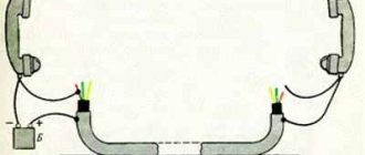
Using telephone handsets. Dialing with telephone headsets is carried out as follows: the capsules in the handset are connected to each other and a battery is connected to them, the voltage of which does not exceed two volts. Thanks to this technique, workers can talk to each other over the phone and coordinate their actions.
Cable wiring diagram using telephone handsets:
You can ring as follows: the cable on one side is connected to the tube conductor, and the other conductor is connected to any core. On the other hand, the cable connects to the tube conductor, and the other to each core in turn. If workers can hear each other on the handset, it means they are connected to the same conductor.
You can see the entire technology of work in this video example:
Using a transformer. There is another way in which you can ring cable lines - this is ringing using a transformer, which has several taps coming from the secondary winding. The technique is as follows: the beginning of the winding is connected to the grounded shell of the conductor, and the transformer taps are connected to the cores and power each of them. If you measure the voltage that exists between the shell at the other end and the conductors, you can determine whether the end belongs to a specific conductor. The dialer will allow you to identify and mark the necessary cores. You can learn how to correctly mark wires from our article.
Concept, purpose of work
The word “continuity” means checking the conformity of the cores of both ends of a wire or cable, and at the same time testing the serviceability. It differs from measuring technical wiring parameters in that exact values are not required. It is enough to establish the actual absence of breaks, short circuits between each other and to the ground, and identify the ends.
It is especially important to check this when secondary switching circuits are organized. Cables, often consisting of a large number of conductors, connect control and protection devices to elements of electrical equipment. In this case, a conductor switched on in the wrong direction without first checking it can cause trouble.
The need for testing arises when you need to do:
- Incoming cable inspection before starting installation work. The purchased wire may be faulty, especially if it was manufactured in violation of technical specifications and was not tested by the manufacturer before sale. It would be a shame to lay a line and then start looking for the location of the fault;
- Check after completion of network installation. Now not only the integrity is checked, but also the ends are marked and marked. Imagine a situation where a dozen and a half lines are installed in the distribution panel, which need to be connected to different circuit breakers. The purpose of the circuits is different, so each of them has its own circuit breaker;
- Circuit testing to localize the location of electrical circuit damage when troubleshooting.
The methods depend on the availability of measuring instruments or devices, the type, and purpose of the line being tested.
The principle of testing and determining resistance
If you carefully examine the multimeter, you will notice that the continuity mode (diode testing) is in the resistance measurement zone. In simple words, continuity testing combines the determination of conductor resistance, analysis of the data obtained and output of the result with an additional sound signal.
To understand the principle of dialing, it is enough to first know Ohm's law. It states: “the strength of the current in a conductor is directly proportional to the voltage at its ends (potential difference) and inversely proportional to the resistance of this conductor.” Based on this rule, resistance R = U ⁄ I, where I is the current strength, U is the network voltage.
Knowing how resistance is determined, it remains to understand where the current and voltage come from during measurements (for safety reasons, the circuit being tested must first be de-energized). It's simple. The multimeter has a power source that creates voltage and supplies current. By comparing the initial data with the amount of loss caused by connecting to the measured resistor, wire or light bulb, the final result is calculated (unit of measurement - Ohm).
Cable and wire testing - methods, diagrams, testers
“CONTROL” and “DIALING” for ELECTRICIAN. When checking the electrical circuit of a machine in noisy workshops, it is not entirely convenient to use indicators with light and sound indications, which are simple and reliable in operation.
Cable locator - generator and receiver
Cable locator - generator KL-1G. Scheme
Cable locator - receiver KL-1P. Scheme
Expert opinion
It-Technology, Electrical power and electronics specialist
Ask questions to the “Specialist for modernization of energy generation systems”
Reviews In principle, any sound generator that produces periodic oscillations can work as a probe, if a controlled circuit is connected to the open circuit of its power supply. Ask, I'm in touch!
Specifics of dialing of some devices
You can use a multimeter not only for cable measurements. Experts use it to measure electrical equipment.
Fuse
Checking the fuse by resistance
Devices in the form of a small box with a thin internal cable prevent overheating and fire of circuit elements. Models without wiring are tested as follows:
- The device is switched to dialing mode.
- The probes are applied to both sides of the fuse.
- When the resistance is 0 Ohm and there is sound, the device works.
- The number 1 appears, there is no sound - the fuse is broken.
Diodes and LEDs
Checking the LED with a tester
The polarity of diodes is represented by a positively charged anode and a negatively charged cathode. For this reason, it only allows current to flow in one direction. When testing, the multimeter is switched to a special mode:
- Probes are placed on anodes and cathodes without reference to color.
- The tester is activated.
- The probes are swapped and the tester is turned on again.
The serviceability of the diode backlight is determined based on the appearance of voltage in the first case and the number 1 in the second.
The polarity of the LED is opposite. It works when there is a plus on the anode and a minus on the cathode. Probes work in a similar way. If the voltage appears and then disappears, the LED is working.
Lamps
After switching the tester to dialing mode:
- Place the first probe on the central contact of the light source.
- Place the second probe on the side contact.
- A malfunction is determined by a buzzer and a 3-200 Ohm indicator.
Testing with measuring instruments
It is easier to perform such a check if you have a measuring device - a tester. The design of the tester, which has a resistance measurement mode, allows you to conveniently determine the circuit closure. The presence of a sound indication mode makes the process faster. There is no need to shift your gaze from the ends of the cable being tested to the indicator.
When testing the insulation of a laid wire or cable, a special device is used - a megger. It supplies the line with a measuring voltage of over 500 volts. Such measurements are made by specialists; such measurements are not performed in everyday life.
A wiring finder using the physical phenomenon of electromagnetic induction helps to find the location of the damage. A magnetic field arises around a conductor carrying alternating current, which is easily detected.
A diagram illustrating the principle of operation of an induction finder is given below:
- The conductivity of the field-effect transistor channel between the drain and the source (the upper and lower electrodes in the diagram) changes with a slight change in the gate voltage (the electrode with an arrow to the left). The electromagnetic field around the wire under load is picked up by the antenna, voltage is applied to the gate - the indicator registers the proximity of the wire. The field strength decreases exponentially with distance, so the field will be best indicated near the cable. At the point where the wires are broken or shorted, the field strength drops sharply, allowing the location of the damage to be determined with high accuracy;
- According to the diagram, the measuring device means a tester turned on in ohmmeter mode. The circuit is practically functional in the form it is drawn, but has low sensitivity. Professional finders are designed according to this principle, but have a more complex circuit with amplifiers and more advanced indication. Cable testing is done with the AC voltage and load turned on.
To test the route of networks disconnected from power, there are similar schemes consisting of two blocks. One of them is a wiring finder, the second is a generator of a signal supplied to the line. Such a system, registering a signal of its own frequency and shape, is more noise-resistant than a simple indication of an electromagnetic field with a frequency of 50 hertz.
Options for wire testing
In general, the term “continuity” of wires includes a wide range of issues, from checking their integrity to determining the insulation resistance of the wire. We are primarily interested in issues related to faults in the wiring of a house or apartment, so we will focus on them.
Checking the integrity of a single piece of wire
The most common problem is a broken wire. It can happen for a variety of reasons, ranging from outside interference to burnout. To determine this damage, you can use a multimeter, a tester, a two-pole voltage indicator with a circuit monitoring function (the most common model is “Contact”) and a single-pole indicator - a screwdriver.
- Let's start with the simplest case, when the wire that needs checking is lying on our table. Before testing a wire with a multimeter, you should turn it on and set the parameter being measured. We will measure the resistance. This value is usually denoted "Ω". If there is no such designation, then we look for values with units of measurement “Ohm” - resistance is measured in these units.
- When testing with a multimeter, you can select any measurement limit. But usually they choose within 100 Ohms. After this, we check the functionality of the multimeter by shorting its two ends. Ideally, it should show 0 Ohm, or a value very close to this.
- Now we take the wire that needs testing and touch the leads of the multimeter to its ends. Ideally, a value should appear as close to 1 Ohm as possible. If the wire has a break, a very large value or “-EL-” will appear.
Multimeter controls
Please note! When touching the leads of the multimeter to the ends of the wire, do not touch the contact part. This may negatively affect the measurement results.
After all, if a person’s insulation resistance is lower than that of the wire, it will show exactly that.
To measure the integrity of a wire with a tester or “Contact”, simply touch the ends of the cable. If a light bulb or diode lights up, this is a signal of wire integrity. Accordingly, if the light does not light, then there is a break. But there are times when it is necessary to determine the integrity of the wire, and only an indicator screwdriver is at hand. In this case, you can also check the integrity of the wire, but our instructions cannot recommend it, because it involves a certain risk
Therefore, it can only be used in extreme cases and very carefully.
Voltage indicator "Contact"
In this case, we determine the phase in the nearest outlet
We insert one end of the wire into the phase terminal of the socket, and at the other, taking all precautions, we check for the presence of voltage. If the wire is intact, then the voltage will be
Determining wire integrity in hidden wiring
But unfortunately, it is not always possible to get easy access to both ends of the wire that needs to be checked. Often they are hidden under a layer of plaster and it is impossible to reach both ends with a multimeter, tester, or indicator. But don't despair! There are ways to test a wire with a tester or multimeter in this case too.
Note! Before drawing a conclusion about a broken phase wire, make sure that there are no switching devices in the circuit. On a car these could be fuses, but in an apartment they could be switches
The photo shows the simplest test of wire integrity
- With the neutral and protective wires, everything is a little more complicated. Since it is difficult to ring a wire with a tester due to the distance of its ends, you need to make sure that this is possible. First of all, we remove the voltage from all the wires located in the junction boxes in which work is to be done.
- Now, using a jumper or regular twist, we connect the wires that require testing. To ensure accurate readings and eliminate errors, it is better to disconnect them from other wires in the box. If there is no protective wire, then after checking that there is no voltage, we connect the neutral and protective wires.
- Now our wires have formed a single circuit. Therefore, in the area opposite to the connection point, we check the presence of a circuit between them. This is done in the same way as in the method described above with a separately located wire.
- You say okay, we know that there is a break, but in which of the two wires? It's simple. If you decide to check the network due to a breakdown, then the break is in the neutral wire. Since the protective wire only provides safety against electric shock and does not affect the performance. If you have a two-wire circuit and you checked by connecting the neutral wire to the phase wire, then we have already checked the integrity of the phase wire.
General purpose test kits with low pass filter
Functionally, these sets are practically no different from those described earlier. However, the inductive probes included in these kits have one additional operating mode:
- broadband (as in the previously described sets);
- — using a 50 Hz filter.
In the 50 Hz filter mode, interference from the power supply is filtered out. This reduces the level of extraneous noise when working in rooms with a large concentration of active equipment (server rooms, data centers, telephone exchanges, etc.)
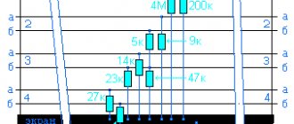
| Fluke Networks PRO3000F50-KIT | Greenlee 801K | |
| Identification of cores in a multi-pair cable | • | • |
| Determining the polarity of a telephone line | • | • |
| Wiring Continuity Testing | • | • |
| Supply of conversational voltage to organize a communication channel over a disconnected line | • | |
| AC noise filter, 50 Hz | • | • |
| Generator output power | +8 dBm | +10 dBm |
| Headset jack | • | |
| Needle-plated crocodiles | • | • |
Cable testing is an essential tool for an electrician.
The standard and most common case is when there is no voltage in any outlet or lighting fixture, and sometimes in all of them at once. In this option, there is no choice - it is necessary to test the cable that powers the entire system, and then individual wires.
As a rule, in the distribution boxes of apartment buildings there is a tangle of unmarked and somehow insulated ends. Switches and sockets, especially in old houses, have long outlived their useful life. It is not easy to understand this intricacy and determine the specific place where the circuit break occurred. We have to check all the elements and re-label the cable cores.
Often the work is complicated by the fact that it has to be carried out without turning off the electrical equipment, but for these situations there are various devices and instruments produced by industry that allow you to find breaks even inside the walls. But in the conditions of a separate apartment or house, wiring can be done in simpler ways:
- • with a complete power outage using a multimeter;
- • or without switching off - with an ordinary light bulb.
We check the wiring in the apartment with a multimeter
Let's take as an example a modern apartment in which the wiring is done in accordance with current requirements and standards. This means that when laying the lighting lines and power outlets, they were separated, and separate wires were laid for them in each of the rooms. Each of these circuits is powered from the apartment panel through a separate circuit breaker.
If the light has gone out in one of the rooms, you should first check that the lamp is working properly. Before starting work, it is necessary to turn off the power to the room/apartment depending on the power supply. When using an opaque incandescent lamp in a lamp, the integrity of the filament is difficult to visually determine, so you will need a multimeter and its continuity function. Let's figure out step by step how to do this correctly.
First you need to check the shield for triggered circuit breakers. In the first case, they will be in the on position (then the fault may be hidden in the room switch, lamp or socket). The likelihood of damage to the wiring in such a situation is low. If the device works, you will need to check everything except the room switch, including the switchboard itself.
If the machines don't work
- Make sure there is voltage at the input and output of the machine. If it is, you can proceed to further verification.
- Prepare the device for operation and check its serviceability by short-circuiting the measuring leads.
- Unscrew the lamp from the socket.
- Touch one of the measuring probes to the base (the metal part of the lamp with threads), and the second to the central contact of the lamp (the insulated center of the end part of the base).
- A sound signal and instrument readings that are different from 0 or 1 mean that the lamp is working. If it is faulty, you need to replace it, which will solve the problem.
- We check the cartridge for serviceability. To do this, you need to disassemble the lamp, make sure that the connected wires and contacts are intact. If everything is in order, then the cause of the failure is not in the cartridge. If malfunctions are detected, they must be eliminated. The lamp cannot be screwed in yet.
- We check the serviceability of the room switch. To do this, remove the plastic cover, unscrew the screws and take it out of the mounting box. We inspect the equipment for the appearance of carbon deposits and check the tightness of the fasteners. If everything is in order, you need to install the measuring ends of the tester on the contacts of the switch. The appearance of a sound signal when dialing in the on position will indicate that the equipment is working properly. The wires do not need to be disconnected.
During such a check, as a rule, a malfunction is identified, which becomes the cause of all the troubles. Eliminating it allows you to quickly solve the problem.
If the machine worked
To ensure electrical safety during work, in this case the voltage is turned off using a general apartment circuit breaker. Next, the serviceability of the socket and the wires connected to the lamp is determined according to the algorithm described above. If there are no faults, you need to check the wiring itself using a multimeter and the continuity function. Such malfunctions happen quite rarely, but they still happen, for example, when installing suspended ceilings or decorative interior elements.
The wiring in this case is performed as follows.
- Using a screwdriver, disconnect the connected conductor (if installed correctly, it is located at the bottom) and move it to the side. The “zero” of this group is, as a rule, located at the zero clamp under the machines.
- Unscrew the incandescent lamp from the socket. Using a ready-to-use tester, we check the line by connecting one of the measuring probes to “zero” and the other to the disconnected conductor. If the device beeps, it means the wiring is shorted.
- In this case, in the room under the ceiling above the switch, we find and open the junction box. We disconnect the wires.
- We check all groups of wires for short circuits. To determine the section of the circuit in which there is a short circuit, we again check the circuits on the apartment panel with a multimeter. If the signal sounds, it means that it is the wire laid from the switchboard to the box in the room that needs to be repaired. Otherwise, the search will need to be continued until a result is obtained.
Security measures
It is important to remember that dialing is working with electricity. Therefore, care must be taken during this procedure. The rules are as follows:
- Use crocodiles that increase the reliability of contact.
- Disconnect the circuit from the power supply before making the dialing; even the batteries must be removed.
- Avoid touching parts of the cable (wire) with your hands.
You might be interested in Induction soldering iron
Do not touch wires with your hands
There are a number of most frequently made mistakes:
- Incorrect setting of measurement modes on the device.
- Incorrect connection of probes.
- Voltage does not meet the required parameters.
- Confusion with instrument scales.
It is important to eliminate the malfunction in a timely manner.
Testing cables and wires is an integral stage of electrical installation work. This procedure has a dual purpose: either to check the wire (cable) for any problems, or to determine the location of the breakdown. There are quite a large number of ways to make a call. To do this, you can use professional instruments (tester and multimeter). It is also possible to carry it out using improvised means. It is important to remember that dialing involves working with electricity. This imposes the need to comply with fairly strict safety regulations. If such rules are strictly followed, then the likelihood of injury is minimal. The dialing itself will minimize the risk of damage to equipment, which is often very expensive.
other methods
When checking multi-wire cables, you have to use other methods for marking the ends:
- System consisting of a power battery and telephone handsets. This check is performed by two people, but is very accurate and effective;
- A method that allows one to do the dialing involves the use of a specially manufactured transformer, the secondary winding of which has taps through a certain number of turns. The measuring core is connected to the lower terminal of the transformer, the rest are connected to the transformer terminals in ascending order of numbering. A voltmeter measures the voltage on the conductors of the other end relative to the signal end. The core with the lowest voltage will be first. The last number has the greatest tension;
- You can do without an assistant using a resistance store. Resistors of the selected value are connected between the conductors of the first end, starting with the signal wire. The conductors of the second side are selected with an ohmmeter in order of increasing resistance.
There are industrial and homemade devices that automate dialing. At the first end, the wires are connected to the corresponding terminals of the transmitting part, the receiver at the second end receives the wire number when touched with a probe.
Independent dialing
It is best to ring the telephone cable using the handset of the device. This method is characterized by simplicity and mobility.
- An assistant is invited.
- The common core is determined. She can be anyone. Others are called in relation to the selected core. The selected one must be ringing initially.
- The first clamp of the main tube is connected to the main core. The second - to the other.
- The first clamp of the auxiliary tube is connected to the main core on the opposite side of the cable.
- The second switches alternately over the others. You need to find the one to which the assistant connected.
- When connected to the desired core, a crackling sound will be heard, indicating the occurrence of a closed circuit.
- A method for marking the detected core is discussed with an assistant. Pre-prepared tags are placed on the ringed type of core on both sides.
- The process is repeated for each subsequent wire.
- If there is no break, the conductors are inserted into the terminal block.
Wiring check
Testing conductors using a multimeter is functionally provided in most digital devices of this class. To set the dialing mode, just set the switch to the position marked with the “Buzzer” icon and prepare the measuring chain shown in the figure.
If current flows through the piece of wire being tested, the multimeter will produce an audible signal (buzzer). Naturally, to test a section of a circuit several meters long, you will need an additional wire used to expand the measuring circuit.
Another option for testing phase and neutral linear conductors of considerable length involves twisting them at the remote end of the electrical wiring.
In this case, to check the circuit for an open circuit, it is enough to connect the multimeter's test leads to the free contacts of those ends of the electrical line that are located closer to the device.
The last of the proposed options has the following advantages:
- using this method, you can use a multimeter to immediately test both wires of electrical wiring connected in a series chain;
- checking the wire in this way is much easier than the first way, since you can do without an additional segment that allows for extension of the measuring circuit.
How to ring wires: methods and devices used
Testing wires at home can be done in two ways: using a multimeter and using improvised means such as an ordinary light bulb with a socket. The last option is somewhat inconvenient, but the first is quite simple and accessible for independent implementation. We will consider both options, since sometimes it happens that there is no device at hand, but the result is needed immediately.
Let's start with the first method, which involves using a multimeter. To make it clearer, let’s look at a simple example and use a wire tester to check the integrity of the wire to connect the computer system unit to the apartment electrical wiring. As a rule, it contains three cores - we will work with them.
How to connect wires photo
We take out a multimeter, turn it on in resistance measurement mode (ohmmeter), close the contact probes and set the indicator arrow to zero. Now let's start testing the cable. We attach one probe to one of the contacts of the plug, and insert the second one in turn into the holes of the connector to connect the cable to the system unit. We observe the indicators of the device, or rather its needle - if the ohmmeter shows the wire resistance within 2-3 Ohms, then the core is in good working order, but if it exceeds 10 Ohms, this is a clear sign that there is a break on this core. It may happen that the multimeter needle does not react at all to your actions - this only means that the contact on the plug and on the connector do not belong to the same core of the electrical wire.
How to test wires with a tester
This is the way to test the wires with a multimeter. I would like to note that this testing method is suitable for wires for any purpose - telephone, computer, electrical.
In almost exactly the same way, you can carry out dialing using a tester equipped with a voltage indicator. It should be understood that no voltage is supplied through a broken wire, and in order to ring the wires with a tester, it is enough to measure the voltage on its wires. On the indicator it should be displayed as identical digital values, which have a different sign (“+” or “-”). The only drawback of this testing method is that the tester is able to determine the parameters of the wire only when it is energized.
Wire continuity photo
Another testing method is suitable for testing exclusively electrical wiring cables - it involves using a piece of ordinary wire with a light bulb. If we are talking about continuity of the lighting circuit, then you can get by with a long piece of single-core wire. The essence of this method is as follows. In the distribution box, the wires leading to one or another consumer of electrical energy are one by one discarded from the general power circuit and instead of them, a separate wire is connected directly to the consumer, the operability of which is beyond doubt. If everything works, then it is the disconnected wire that can be considered faulty. If not, then we restore it to its place and repeat the operation with another wire of the electrical circuit.
In principle, by changing the starting point of connecting the additional wire and using a lamp as an indicator, you can ring almost any section of the apartment wiring. The method is excellent, and most importantly effective - its only drawback is some inconvenience associated with constant switching of wires.
How to test wires with a multimeter photo
Test method
The basic principle of continuity testing is to organize a circuit of current flow through the conductor being tested. Serviceability will be indicated by a sound or light indicator connected through the cable being tested to the power source. The following diagrams illustrate the design of a basic tester, which can be easily made independently from available components:
- Use a flashlight bulb with a battery. The lamp of the connected device will light up when a short circuit is created at the opposite end. The operating voltage of the lamp must match the source;
- A more energy-efficient option would be to use a semiconductor LED instead of an incandescent lamp. The LED is not afraid of shaking and will not break if accidentally hit. The resistor protects the indicator from overcurrent;
- It is more convenient to use sound indication. You can use any sound indicator, for example, a bicycle or moped turn signal.
The ease of manufacture and the simplicity of the circuit of these connections make it possible to effectively test the wire. The verification method looks like this:
- Connect the circuit leads to the bare ends of the wire on one side. The absence of indication indicates that there is no short circuit;
- Short the wires at the other end. Light or sound indicates serviceability, confirms that this is exactly the line that is needed;
- If necessary, the insulation is checked. To do this, remove the jumper and connect one connection terminal to, for example, a metal pipe in which the cable lies. We alternately connect the second terminal to each of the cores. No reaction will indicate that the sheath was not damaged when pulled into the pipe or metal corrugated hose.
The described circuits simplify the incoming inspection of the serviceability of conductors before starting installation work.
Checking the electric heating element
You can also ring an electric water heating element with a multimeter. To do this, the probes of the device must be attached to the contact plates of the heating element. If the resistance reading is small, then the heating element is working. With very large values or one (depending on the model), the heating element is damaged and requires replacement.
Note! Sometimes one housing may contain two heating elements connected to voltage in parallel. In this case, you need to ring them separately, having first removed the jumper between them
It is very important for boilers and other water heating devices to ring the contacts of the heating element for penetration into the body. To do this, the probe is connected to one of the contacts, and the second - to the body of the heating device
If the tester shows a certain value, the internal insulation has been damaged in this heating element. To prevent electric shock, the heating element must be replaced.